In this post I will show how to construct an Mp3 player using arduino and DFPlayer. The proposed article has two Mp3 player designs, one with push button control and another one with IR remote control. We will also take a look at DFPlayer (Mp3 player module) and its specifications.
We all love music, we would like to hear it while at gym, reading, moments before sleeping or while soothing our self after a hard day work.
Constructing a music player at home few decades back was a near impossible for an electronics enthusiast because of constructional complexity due to mechanical components.
In those days only limited number of songs could be accommodated in a cassette. Replicating a song to another cassette was a nightmare too. But now, thanks to advancement in electronics an Mp3 player can be made from scratch with your pocket money.
Now let’s move on to technical details of the project.
The heart of the project is DFPlayer which is a small Mp3 player module which can accommodate micro SD card and can be controlled using a microcontroller.
Illustration of DFPlayer:
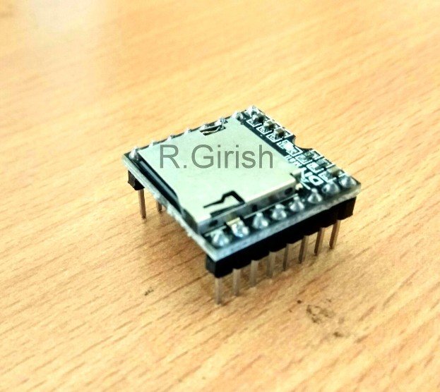
It has in-build amplifier which can drive 3 watt loudspeakers in stereo or mono. It has 24-bit digital to analog converter (DAC) which is pretty good for such low cost and compact module.
Bottom view of the DFPlayer:
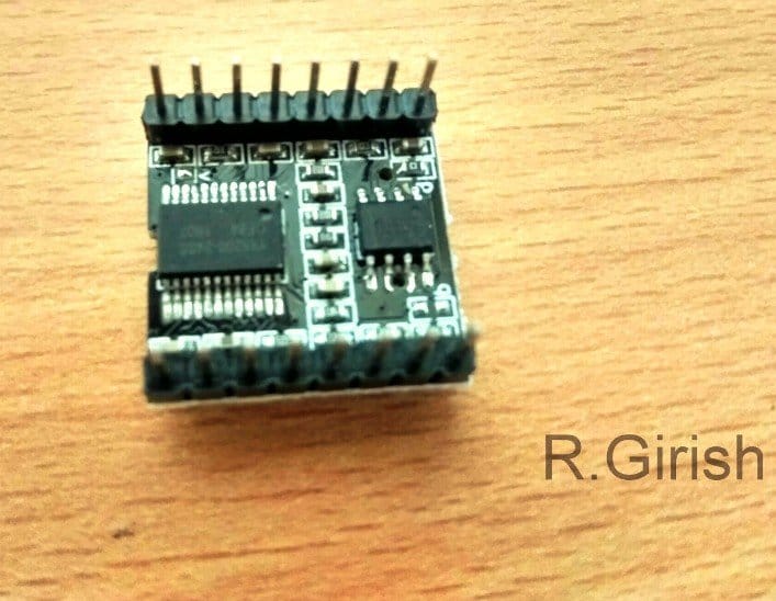
It supports MP3 and WMV hardware decoding. It supports sampling rate of
8KHz,11.025KHz, 12KHz,1 6KHz, 22.05KHz, 24KHz, 32KHz, 44.1KHz, 48KHz.
It can support up to 32GB micro SD card. It supports up to 100 folders, each folder can be assigned up to 1000 songs.
It has 6 different levels of equalizer; and 30 levels of volume adjust control. It can operate from 3.2V to 5V.
Pin configuration of DFPlayer:
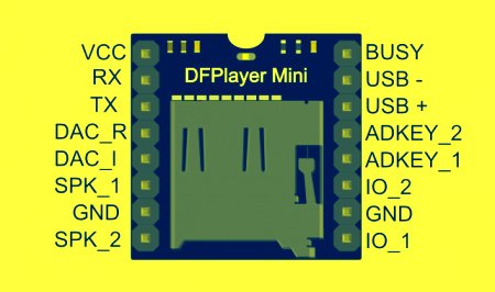
The above specifications are based on DFPlayer’s data sheet.
By now you would have familiar with DFPlayer and its specification. You can purchase this module from e-commerce sites or from local electronics market.
Now let’s jump into the schematic diagram.
Push-button Mp3 player design:
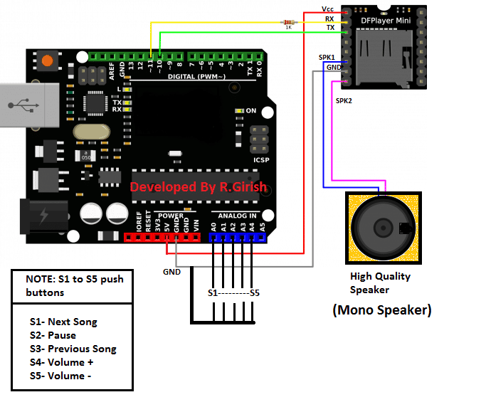
The above circuit is very simple; the arduino sends commands to the DFPlayer module to control the songs. The user can input their choice via push buttons.
The arduino’s built-in pull-up resistor has been activated in the program, so that we no need to attach a physical resistor to push buttons.
Try to use good quality speakers; the DFPlayer can deliver very good quality sound.
If you find any distortion in the sound at higher volume levels, power the DFPlayer module externally at 5V DC with common ground connection between arduino and DFPlayer.
If you want stereo sound setup, connect the one of the speaker to SPK1 of DFPlayer and another speaker to SPK2 and ground the remaining speaker wires.
Program for push button control:
//---------Developed by R.Girish------//
#include <SoftwareSerial.h>
SoftwareSerial mySerial(10, 11);
# define Start_Byte 0x7E
# define Version_Byte 0xFF
# define Command_Length 0x06
# define End_Byte 0xEF
# define Acknowledge 0x00
const int btnNext = A0;
const int btnPause = A1;
const int btnPrevious = A2;
const int volumeUP = A3;
const int volumeDOWN = A4;
int volume = 15;
boolean Playing = false;
void setup ()
{
pinMode(btnPause, INPUT);
pinMode(btnNext, INPUT);
pinMode(btnPrevious, INPUT);
pinMode(volumeUP, INPUT);
pinMode(volumeDOWN, INPUT);
digitalWrite(btnPause, HIGH);
digitalWrite(btnNext, HIGH);
digitalWrite(btnPrevious, HIGH);
digitalWrite(volumeUP, HIGH);
digitalWrite(volumeDOWN, HIGH);
mySerial.begin(9600);
delay(1000);
playFirst();
Playing = true;
}
void loop ()
{
if (digitalRead(btnPause) == LOW)
{
if(Playing)
{
pause();
Playing = false;
}
else
{
Playing = true;
play();
}
}
if (digitalRead(btnNext) == LOW)
{
if(Playing)
{
next();
}
}
if (digitalRead(btnPrevious) == LOW)
{
if(Playing)
{
previous();
}
}
if(digitalRead(volumeUP) == LOW)
{
volumeINC();
}
if(digitalRead(volumeDOWN) == LOW)
{
volumeDEC();
}
}

void playFirst()
{
exe_cmd(0x3F, 0, 0);
delay(500);
exe_cmd(0x06, 0, volume);
delay(500);
exe_cmd(0x11,0,1);
delay(500);
}
void pause()
{
exe_cmd(0x0E,0,0);
delay(500);
}
void play()
{
exe_cmd(0x0D,0,1);
delay(500);
}
void next()
{
exe_cmd(0x01,0,1);
delay(500);
}
void previous()
{
exe_cmd(0x02,0,1);
delay(500);
}
void volumeINC()
{
volume = volume+1;
if(volume==31)
{
volume=30;
}
exe_cmd(0x06, 0, volume);
delay(500);
}
void volumeDEC()
{
volume = volume-1;
if(volume==-1)
{
volume=0;
}
exe_cmd(0x06, 0, volume);
delay(500);
}
void exe_cmd(byte CMD, byte Par1, byte Par2)
{
word checksum = -(Version_Byte + Command_Length + CMD + Acknowledge + Par1 + Par2);
byte Command_line[10] = { Start_Byte, Version_Byte, Command_Length, CMD, Acknowledge, Par1, Par2, highByte(checksum), lowByte(checksum), End_Byte};
for (byte x=0; x<10; x++)
{
mySerial.write(Command_line[x]);
}
}
//---------Developed by R.Girish------//
Now let’s move on to IR remote based design.
Schematic for IR controlled Mp3 player:
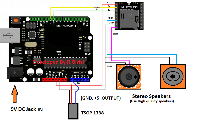
The above design is simple as the push button based; the only difference is removal of push buttons and inclusion of TSOP 1738 IR receiver. The received signal from IR remote is fed to A0 pin of arduino.
Now to control this Mp3 player you need a spare TV, or any other IR based remote which might be lying on your junk box. You have to decide which the buttons for controlling the functions like play & pause etc.
There are 6 functions:
1) Play and pause
2) Next song
3) Previous song
4) Volume increase
5) Volume decrease
6) Sound equalizer (Normal/Pop/Rock/Jazz/Classic/Base)
You need to choose the buttons on the remote and find its Hexadecimal codes of those buttons which will be transmitted by the remote. To find the hexadecimal code, download the IR library if not done so.
github.com/z3t0/Arduino-IRremote
Add the library to arduino software and navigate to File> Examples> IRremote > IRrecvDemo and upload the code with completed hardware setup.
Open the serial monitor and press the buttons on remote, you will see the hexadecimal codes, note it down to corresponding button on piece of paper.
You need to enter the hexadecimal code on the program given below. Once you entered the hexadecimal codes in the given program, upload it. You are ready to control your songs from your remote.
Program for IR remote based design:
//---Developed by R.Girish--//
#include <SoftwareSerial.h>
#include <IRremote.h>
SoftwareSerial mySerial(10,11);
# define Start_Byte 0x7E
# define Version_Byte 0xFF
# define Command_Length 0x06
# define End_Byte 0xEF
# define Acknowledge 0x00
//--------------------------------------------------------//
# define pause_play 0x2FD08F7
# define next_song 0x2FDD827
# define prev_song 0x2FDF807   //REPLACE THESE HEX CODE WITH YOUR REMOTE BUTTON CODE STARTS “0x”
# define vol_inc 0x2FD58A7
# define vol_dec 0x2FD7887
# define sound_equalizer 0x2FD30CF
//-------------------------------------------------------//
const int receive = A0;
IRrecv irrecv(receive);
decode_results dec;
int volume = 15;
int eqset = 0;
boolean Playing = false;
void setup ()
{
irrecv.enableIRIn();
mySerial.begin(9600);
delay(1000);
playFirst();
Playing = true;
}
void loop ()
{
if(irrecv.decode(&dec))
{
if (dec.value==pause_play)
{
if(Playing)
{
pause();
Playing = false;
}
else
{
Playing = true;
play();
}
}
if (dec.value==next_song)
{
if(Playing)
{
next();
}
}
if (dec.value==prev_song)
{
if(Playing)
{
previous();
}
}
if(dec.value==vol_inc)
{
volumeINC();
}
if(dec.value==vol_dec)
{
volumeDEC();
}
if(dec.value==sound_equalizer)
{
equalizer();
}
irrecv.resume();
}
}

void playFirst()
{
exe_cmd(0x3F, 0, 0);
delay(100);
exe_cmd(0x06, 0, volume);
delay(100);
exe_cmd(0x11,0,1);
delay(100);
}
void pause()
{
exe_cmd(0x0E,0,0);
delay(100);
}
void play()
{
exe_cmd(0x0D,0,1);
delay(100);
}
void next()
{
exe_cmd(0x01,0,1);
delay(100);
}
void previous()
{
exe_cmd(0x02,0,1);
delay(100);
}
void volumeINC()
{
volume = volume+1;
if(volume == 31)
{
volume = 30;
}
exe_cmd(0x06, 0, volume);
delay(100);
}
void volumeDEC()
{
volume = volume-1;
if(volume == -1)
{
volume = 0;
}
exe_cmd(0x06, 0, volume);
delay(100);
}
void equalizer()
{
eqset = eqset+1;
if(eqset == 6)
{
eqset = 0;
}
exe_cmd(0x07, 0 ,eqset);
delay(100);
}
void exe_cmd(byte CMD, byte Par1, byte Par2)
{
word checksum = -(Version_Byte + Command_Length + CMD + Acknowledge + Par1 + Par2);
byte Command_line[10] = { Start_Byte, Version_Byte, Command_Length, CMD, Acknowledge, Par1, Par2, highByte(checksum), lowByte(checksum), End_Byte};
for (byte x=0; x<10; x++)
{
mySerial.write(Command_line[x]);
}
}
//---------Developed by R.Girish------//
NOTE 1: you may see warning in the program while compiling, please ignore it.
NOTE 2: Try to put all your songs in SD card without folders.
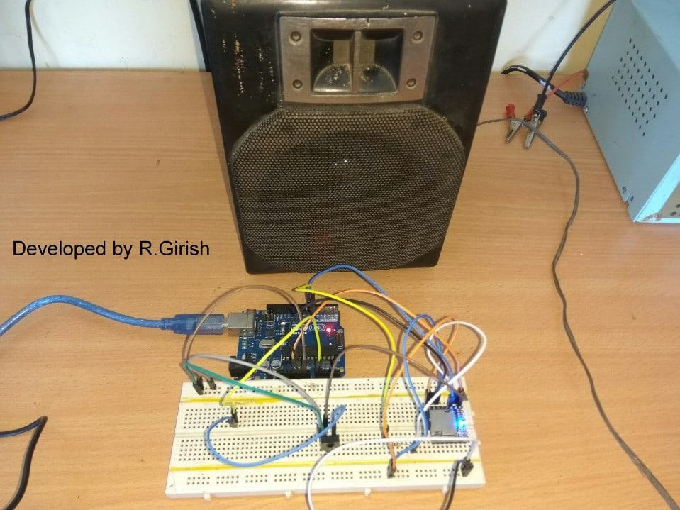
Author’s prototype:


Questions & Answers
have mp3-tf-16p module and 20 led’s wired .
would like to have led’s blink with music beat.
HELP !
th
gk
ohio
How did you wire the 20 LEDs?
Will wire anyway that works to get leds to beat with music. Have player and nano board. Have mp3tf16p working
In that case, you can try one of the circuits, explained in the following article:
https://www.homemade-circuits.com/how-to-make-simple-vu-meter-circuit-at/
https://www.homemade-circuits.com/led-music-level-indicator-light-circuit/
Hello
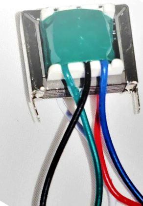
I am trying to restore an old electric organ. There is a transformator with conection to the loudspeaker / jack plug.
What is the function of this ?
It is sitting on an a print card with 3 capasitors.
Hi, that small transformer could be the audio output transformer.
Hi
Thank you for the answer. I found out that could be a filter, but why use a transformator ?
It may be difficult for me to analyze without seeing the schematic, however whenever a speaker is connect with a transformer output, it is mostly an audio output transformer, which is not used only as a filter, rather for impedance matching and isolation between the amplifier and the speaker/jack. The capacitors around could be working along with the transformer’s inductance to shape the frequency response, so in that way it might also behave like a filter network.
Thank you very much. Now I know what it is.
You are welcome Bjarne!
Good afternoon.
I would like to ask for information /help, I am lay in the subject of arduino, I built a chapel in the garden and I would like to put a digital bell sound because a real bell is very expensive. I got an arduino scheme for this, but he’s set to play a very weak speaker, I wanted to add a power in the electronic scheme but I don’t know how to do it. Could you, when you have a little time, take a look at the drawing? It is possible to give me a little guidance, if yes my email is quim.helio@gmail.com if you wish, I can send you the drawing of the scheme to better understand what I am describing. I thank you very much for your attention.
Hi, yes if you connect the speaker directly to the Arduino output then the audio will be very weak.
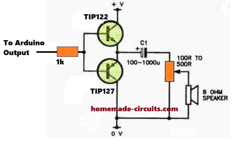
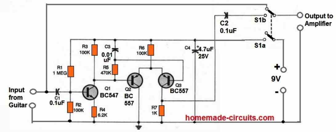
But you can easily amplify the audio loudly using a simple BJT amplifier stage at the output as shown below:
Please let me know if you also did the same in your schematic, I will try to figure it out….
Ola Swagatam
First thanks for answering me.
My scheme is different, I did not find a way to send the image here in the comments, but if you call me in the email quim.helio@gmail.com i can send you the image and the program code, which incidentally was the chatgpt that helped me to do, because as I said I am lay on the subject.
I await your return, if possible in the email, so I can send you
Thanks Helio,
Can you please send them to my email ID:
homemadecircuits
@gmail.com
OK … estou enviando agora mesmo …
Thank you Helio, I checked the diagram, the transistor concept look OK to me, except their Ground connections, which must be directly connected with the 5V ground supply:
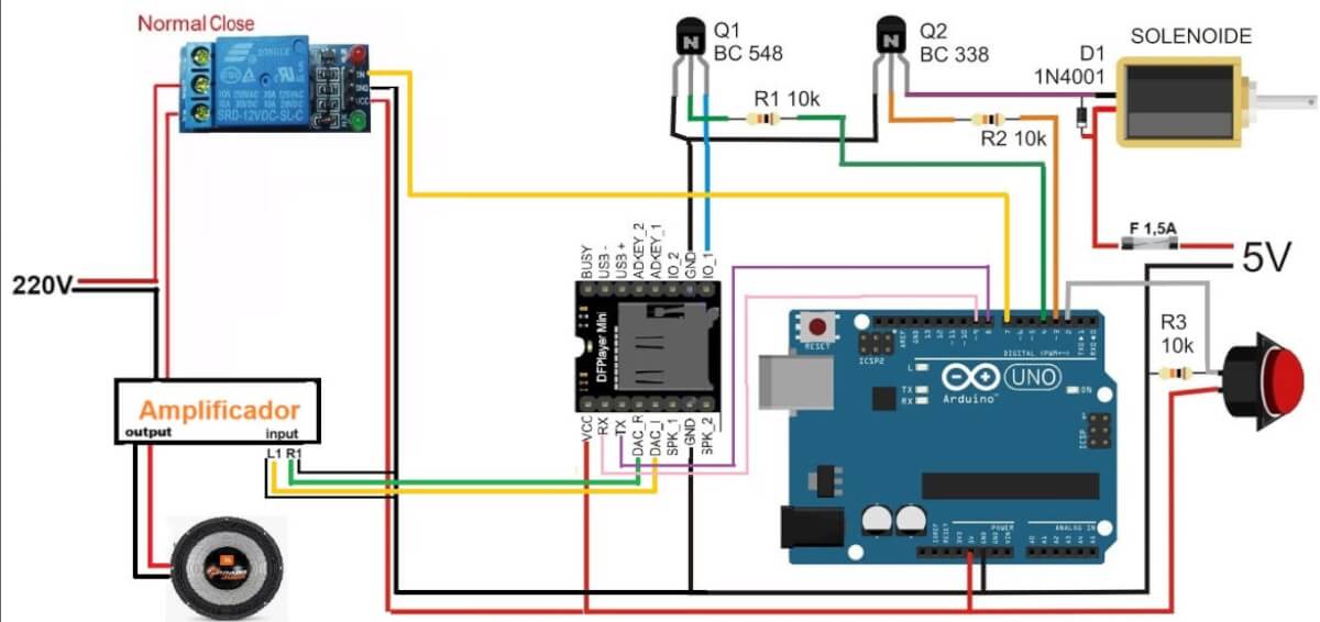
So please connect the transistor emitters directly with the 5V ground or the 0V line.
Also, the transistor emitters orientations are incorrect.
So please swap the collector/emitter pins with each other.
Please check the datasheet for the pin orientation of the BJT, both BC337 and BC548 have the same emitter orientation, which is on the right side, not left side.
https://www.mouser.com/datasheet/2/149/BC337-193546.pdf?srsltid=ARcRdnofJdqDsNQ99T_s-WcQRkEtNuF9oGR0NdM0QIS51ZdOC6rAJDpE
Ola Swagatam
I’m not from the electronics area, I got here with the help of readings and chatgpt, but I can not understand this part that mentioned, if possible, you make this note in the own drawing I sent you ? i will not continue with this experiment, I just wanted to ring the sound of the bell in the small church of the garden, please help me, draw in the very image I sent you, if you have time and can, of course, I will be very grateful . if you can make it work I will send photo and video in the little church .
No problem Helio,
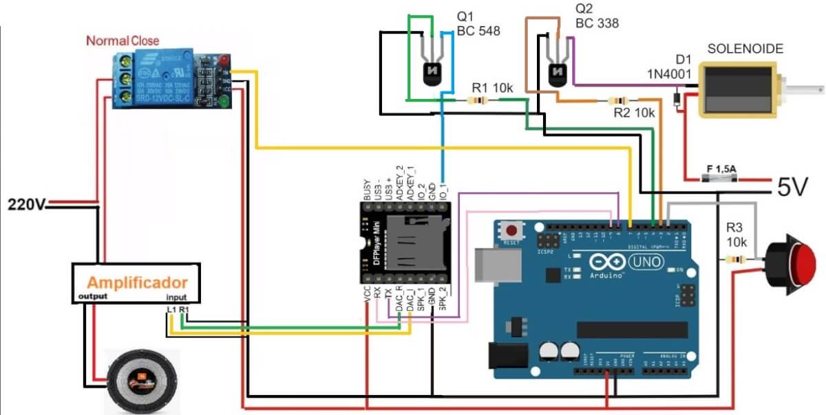
Here’s the corrected diagram for you:
I have corrected the transistor configuration and the ground connections.
However I did not check the DFP module because I have not studied the connections of this module, and i am not sure about it…
Please let me know if you have any doubts regarding this topic…
Quick quuestion:
I want the program the remote to play certain tracks. I have the same remote as you in the video.
I want button 1 to play track one, so on and so forth. How would you code this?
I’ll try to contact the author of the article for clarification on this, if possible…
as i understand the formular. example DATA= R1=22k C1=22uf SOLUTION Since the formular is F=1/8.8RC therefore F=1/8.8*22*22=54.4 aproximatly is 50Hz ??
C will be in Farads and not in uF (according to me), after calculating you will have to confirm it with a practical set up…
I have seen it. please Sir help me to calculate for CD4047 R1 and C1 for me
you can refer to this article for the formula
https://www.homemade-circuits.com/2013/09/ic-4047-datasheet-pinouts-application.html
Choose the better one for me please. meaning that i want the one which i will able to power my TV, CEILLING FAN, DVD PLAYER, SETTLITE RECIEVER
OK, you can try the second circuit from this link
https://www.homemade-circuits.com/2013/10/pure-sine-wave-inverter-circuit-using.html
thankx sir. sir i want to make a 1000 watt inverter fron your circuit please provide a link to me
do you want it to be a sine wave or square wave, please specify….
Sir please see this link may i subtituate 2N3055 with IRF3205??
Bashir, it's an absurdly designed inverter circuit….the LM324, and the BJT are unnecessarily introduced, and are an overkill.
if you want to use mosfet with IC4047, you can very well do it by directly connecting the mosfet with the IC pinouts through a 10 ohm resistors and a reverse 1N4148 diodes connected in parallel with the resistors….for better safety put 1K resistors across gate/source of the mosfets.