The IC LM386 is a 8-pin tiny power amplifier chip, specially made for operating under relatively low voltage parameters, yet provide considerable amplification.
IC LM386 amplifier circuit becomes suitable for applying in small low power audio gadgets like in FM radios, door bells, telephones etc.
Let's begin the IC LM386 amplifier explanation by studying its absolute maximum ratings first, meaning the parameters which should not be exceeded while using this IC in any circuit:
Technical Specifications of IC LM386
- Supply Voltage: 4V to Max. 15V (Typical)
- Input Voltage: +/- 0.4 volts
- Storage Temperature: -65 degrees to +150degrees Celsius
- Operating Temperature: 0 to 70 degrees Celsius
- Power Output: 1.25 watts
- IC manufactured by: National Semiconductor
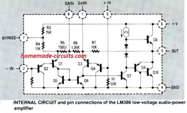
Internal Schematic
How to Control Gain for the IC LM386
In order to make the IC better with its response, its pin#1 and 8 have been attributed with a gain control facility which may be set externally.
Gain simply means the capacity or the amplifying level of the device up to which it is able to amplify the applied input low signal audio input.
When the above pin outs are kept unconnected to anything, the internal 1.35K resistor sets the gain of the IC to 20.
If a capacitor is joined across the above pin outs, the gain is suddenly lifted to 200.
The gain may be simply made adjustable by connecting a pot in series with the above explained capacitor across the pin 1 and 8.
Practical Application Amplifier Circuits Using the IC LM386
The following figure shows a typical IC LM386 amplifier circuit having the bare minimum number of components required to make the IC operate at its internally set level of gain 20.
Having Gain of 20
The speaker used is a 2 watt, 8 Ohms type.
The input at Vin may be fed from any audio source such as a cell phone headphone socket, a CD/DVD player RCA L or R socket or any other similar source.
The pin Vs should be connected to +12V DC supply from an AC DC adapter or a home made transformer/bridge power supply unit.
Pin #4 should be connected to ground or the negative of the power supply.
The earth wire or the negative wire from the input audio source should also be connected to the above negative of the power supply.
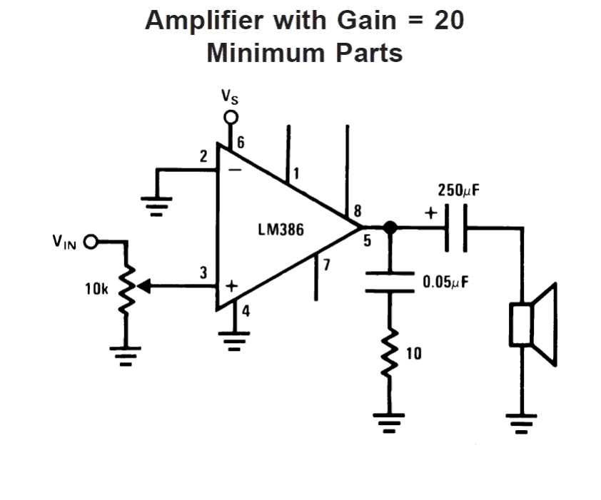
The input pin#2 goes to a 10K pot which becomes the volume control, one of its end terminals is picked for receiving the input signal while the other end is connected to ground, the center one goes to the hot end of the IC.
The speaker is connected to in #8 via a high value blocking capacitor, the resistor/capacitor arrangement connected across pin #5 and ground has been included for frequency compensation and to provide greater stability to the circuit.
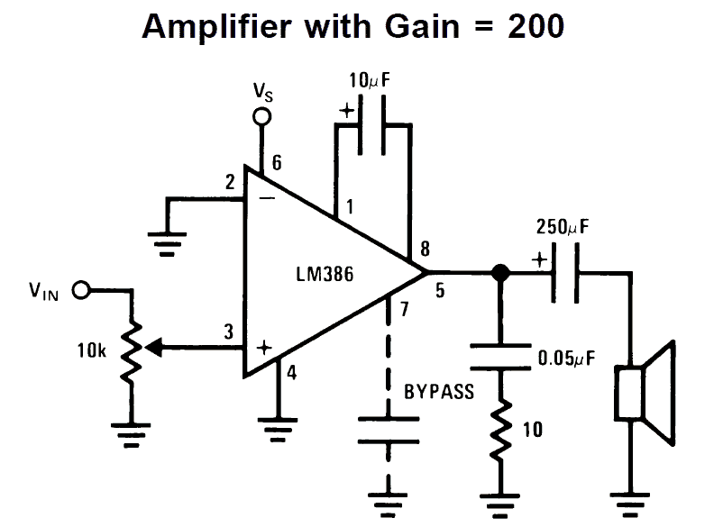
Having Gain of 200
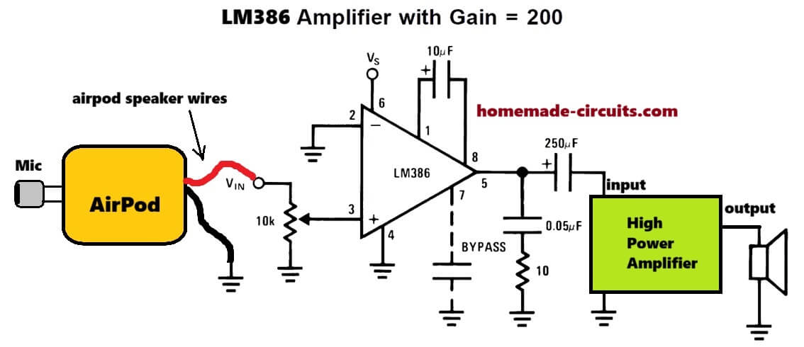
The next circuit shows a similar design as above, except that its pins 1 and 8 have been connected to a capacitor of 10uF, which as explained above helps to pull the gain of the amplifier to 200
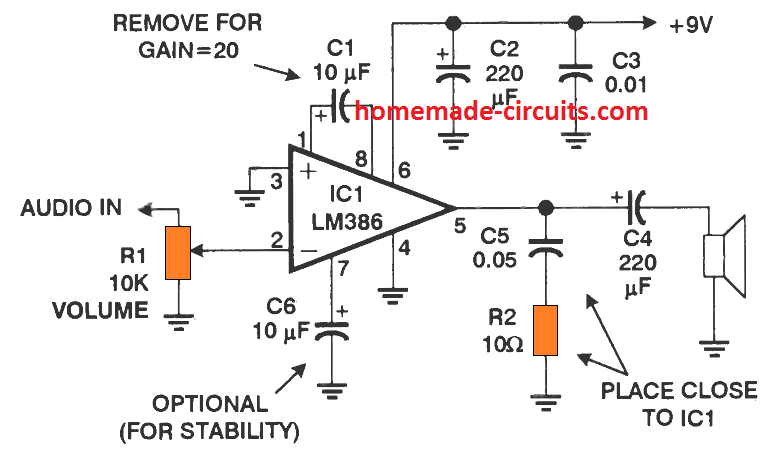
Detailed LM386 Circuit Diagram with Instructions
Application Circuits
From the above discussion we have learned that the LM386 is versatile little audio amplifier IC which can be applied in many different small audio related circuits quickly and with great efficiency.
The following are a few application circuits using IC LM386 which you an build and have a lot of fun.
MIC amplifier circuit using LM386 IC
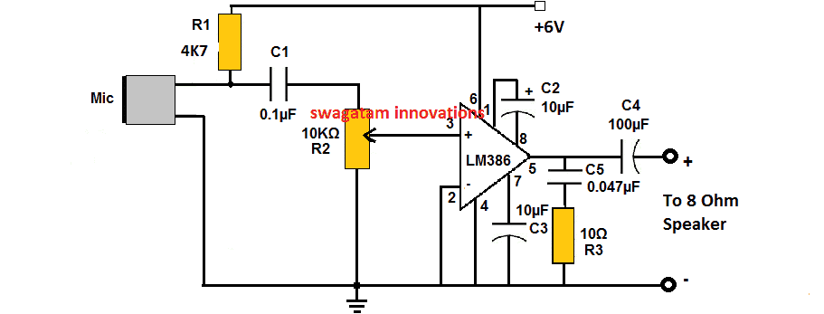
The following image shows how the above explained LM386 may be applied for achieving a simple yet powerful microphone amplifier circuit as shown below
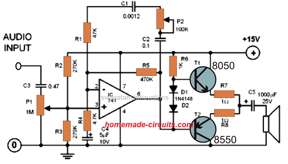
LM386 Amplifier with Bass Boost
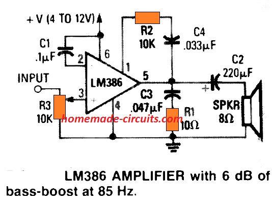
So far we know that attaching a 10-µF electrolytic across pins 1 and 8, it is possible to enhance the actual gain of the circuit to 200. This happens due to the capacitor appropriately shorting out the IC's in-built 1.35K resistor.
The figure above illustrates the way to shunt that resistor by implementing C4 -R2, to allow 6 -dB of bass boost at 85 Hz. This compensates the actual inability of the chip to produce suitable bass effect through typically used low-cost 8 ohm speakers.
AM Radio Circuit
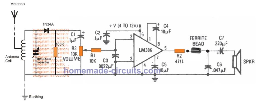
The figure above shows how the LM386 amplifier design could be customized like a compact amplifier for making a simple AM radio. Here, the detected AM transmission is supplied to the non-inverting input of the IC through volume control pot R3, and the resulting RF is de-coupled by way of R1, C3.
Any sort of left over RF disturbances are blocked from passing on to the loudspeaker through the indicated ferrite bead. In this LM386 AM radio design, the voltage gain of the IC is set at 200 through C4. You can also see that the circuit is supplied through supplemental power supply ripple rejection stage by configuring C5 between pin 7 and the negative line.
Infrared Decoder Amplifier
The next LM386 IC application circuit shows how the IC can be configured like an infrared receuver, amplifier and decoder.
Any infrared transmitter can be used to send the signal to this receiver. The LM386 receiver will receive the IR signals and convert them into audio signals through the connected loudspeaker.
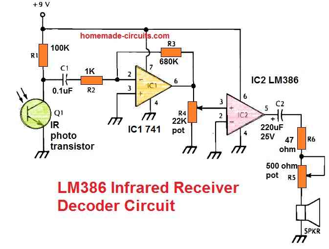
This receiver is intended to decode and demodulate all sorts of IR light beams that are amplitude-modulated (AM) and operate a loudspeaker. R5 is an optional volume control that may be removed. Q1 should be positioned properly and sheltered from stray incident light.
LM386 Signal Tracer Circuit
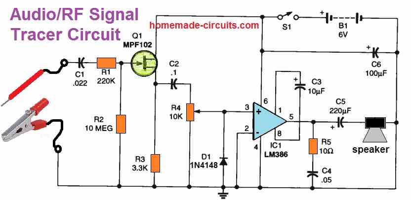
The AF/RF Signal tracer's schematic can be seen above. Q1 amplifies the input probe signal while R1 and R2 provide a bias for the FET.
R4 (the volume control) and D1 are capacitively linked to the amplified signal. Diode D1's function is to demodulate RF signals.
The signal is unaffected by D1 if you are working with audio signals. On the other hand, when dealing with RF signals, the diode behaves like a demodulator from a vintage crystal set.
The introduction of D1 increases the adaptability of the AF /RF Signal tracer. Signals that are phase-modulated or frequency-modulated (FM) or both can be detected; D1 serves as a slope detector. However, the audio quality will be substandard.
The last component of the circuit is a typical LM386 amplifier with an 8-ohm output and a gain of 200. The output of the IC LM386 may be connected to any compatible speaker or earphone.
Due to the coupling between S1 and R4, the AF/RF Signal tracer may be turned on and off by adjusting the volume, just like a battery-operated radio. A total of four AA batteries in a suitable holder serves as the power supply.
Simple Buzzer Circuit
An exact buzzer-like sound is produced by the circuit displayed below. Just a couple of ICs and a few other parts are needed to build this circuit.
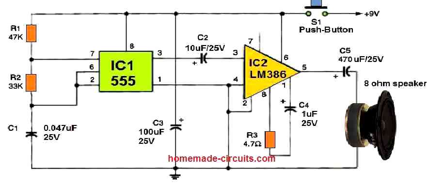
Through resistors R1 and R2, C1 begins to charge as soon as S1 is briefly pushed. In the end, it activates pin 2 of IC1's 555 oscillator/timer.
The IC subsequently starts discharging the capacitor by pushing pin 7 low via R2. As long as S1 remains pushed ON, this cycle happens repeatedly.
The pin#3 output of IC1 switches ON/OFF in response to the capacitor's charging and discharging, providing a sound frequency to IC2. IC2 is an LM386 low-voltage audio power amplifier that boosts the loudness of the tone frequency.
The sound frequency from IC1, which sounds like a genuine buzzer, is amplified by IC2 and reproduced through the speaker.
For a low-frequency buzzing sound, you can increase the value of C1 to 0.1 uF. For improved stability, you may also use a 47-F capacitor to bypass pin 7 of IC2 to ground.
Mini Megaphone Circuit
A min megaphone circuit can be built using single LM386 IC as shown in the following figure.
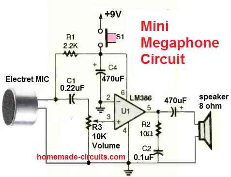
A megaphone is a hand held device with a MIC where the user can speak, so that the voice is amplified and can be listened over a larger distance.
The circuit utilizes a single LM386 IC, an electret MIC, and a small loudspeaker. It also includes a volume control pot for adjusting the loudness or the output amplification.
When the user speaks on the MIC, it is amplified through the loudspeaker allowing the user to address his or her speech loudly to the present audience.


Questions & Answers
Thanks, can the modified AIRPOD BLUETOOTH SPEAKER work with wireless Microphone 🎤. Please how can I do the connection to the wireless Microphone and the circuit requires.
sorry I did not understand, please explain your circuit connections in details..
Thank you, for the AIRPOD BLUETOOTH SPEAKER circuit,I got the circuit clearly but the HIGH POWER AMPLIFIER part, can I use the LM386 AMPLIFIER with 6dB of bass-boost at 85 HZ circuit in this article as the HIGH POWER AMPLIFIER circuit or you can give me another circuit design for the HIGH POWER AMPLIFIER Circuit
I think you can use the high power amplifier directly in place of the LM386 amplifier, and eliminate the LM386 completely…
You can get the high power amplifier circuits on this page….or you van buy one:
https://www.homemade-circuits.com/?s=power+amplifier
Thank you very much Engineer, you are highly appreciated, I got the details.Thank you very much God will Continue to bless you
You are most welcome!!! Let me know if you face any further problems I will be happy to help!
Thank you very much.(1) I have opened the Airpod (Bluetooth Earphone) two wires red and black is connected to the tiny speaker (earpiece )AND two wires is connected to the Mic (mouth piece) please how can I connect the wires from the Speaker and Mic (mouth piece )to the 200 Gain IC LM386 circuit (2) Do I have to connect Mic Amplifier circuit to this circuit also.(3) please help me confirm it, you said speaker is connected to pin #8 in your write-up but in your diagram the speaker is connected to pin #5 via 250 uf polarized capacitor.(4) please help me design simple High Power Amplifier circuit to connect the 200 Gain LM386 circuit to complete the Bluetooth wireless speaker.Thank you very much
OK, please checkout the following diagram, you must do the connections as shown here….remember the airpod ground, LM386 ground, and the power amplifier ground, all must be connected in common.
hiya, Swagatam
There is the LM 386 circuit for Bass Boost. But what about Treble boost?
Needed for a hearing aid idea which needs a cutoff freq around 1.5k Hz (.1u with 1k ohms) and higher. Using a build LM 386 kit from Amazon modified with the mic/speaker output to earbuds. Works well but amplifies all and was looking for some adjustment ideas.
Note: hard part was the TRRS wiring for mic/speaker connections.:)
Thanks
Hey Dajax, thanks, yes it seems the treble part is not included in the design.
I guess it is better to include a passive bass treble network at the input side of a standard LM386 amplifier with 200 gain, and then we can check the response.
You can get the passive circuits from the following article:
https://www.homemade-circuits.com/simple-tone-control-circuits/
Let me know how it goes.
Not sure I’m doing this right, here goes. I am an 87 year old electronics nerd with nearly 4 decades lab tech in aviation under my belt at General Dynamics & 33 years at Cessna Aircraft. Mostly test lab work and built most of our test equipment. However weak on audio. Got lots of parts including LM386-3 and -4. Can’t seem to get much audible sound out of either one. Signal source is what is in the area. Here is what I have trouble with. Electret mic, weak signals. Tried IC and transistor circuits with poor results. Cannot use prosthetic devices on my ears or head, body rejects them. Need lM386-4 & 9 volt power to have mobility.
Hi, I guess you have already tried the following design, if this basic design is not amplifying enough then I think one of the parts in your circuit might be faulty. I hope you are building the circuit by soldering them on a PCB, and not on a breadboard:

I have played with these ICs a lot and have never faced any problems.
If you touch the input of the above circuit with your finger you should be able to get a loud buzzing sound on the attached speaker, which would confirm that the circuit is working alright.
Hi Swagatam, appreciate your quick response. I am a deeply involved with solder work having spent nearly 40 years in aviation. I also build all my circuit work on breadboards before building to keep time and costs down due to any errors by me or comments. I have a version similar to what you showed built on perforated board and it works. Also did a circuit about the same as yours and then took the output of the 386 chip and input it to an LM380 to help boost the output. Have tried all kinds of preamps with IC preamps and still volume is not good. I also set board near computer speaker and the amplified music from computer played just fine with suitable volume. I blame the electret mic. I have been chasing this for weeks and built several breadboard arrangements using a 2N3904 transistors. I had been using LM386-3 chips for the supplier I buy from did not have -4 (1 watt). I now have 8 of them to try. I have many electret mic preamp circuits I’ve tried and still little volume.
In all ways not so good on breadboard, same problem when circuit layed out properly and soldered. The electret mic-s I get from the supplier requires 4.6 volts bias voltage. I use a 10k pot when circuit is completed, measure mic volts to make sure I have between 4.5 top 10 volts max. I am using 9 volt battery or even with power supply even 12 volts on the positive buss. Jameco Electronics in California.
Thank you Ray, for your detailed explanation,
In that case it seems the problem could be with the MIC circuit, however electret MICs are quite reliable and again I have never faced any issues with these devices myself.
You could probably try the first circuit from the following article to test your MIC working capacity and efficiency.
This circuit should activate the relay or any connected load in response to a relatively loud sound such as a clap sound, etc:
https://www.homemade-circuits.com/simplest-sound-activated-relay-switch/
Although it looks like an overkill, it’s worth trying.
Found out these Mic’s came from China, had to pay duty on them. Here is the stats on these Mic’s. I’m not comfortable with them.
Uh oh, can’t post image here apparently. May I have your email link so I may send you these stats and a photo of the curve on the little critters from my email to yours?
Sure, here’s my email Id:
homemadecircuits
gmail.com
Good morning, appreciate your help. I was a radioman in the Navy for 4 years. Once out, had lots of fun with my sons teaching them code. Then discovered the 555 chip. Made a code oscillator that I can adjust to fit the frequency tone I want. I use this as the audio signal to ring out these circuits. I also have built training aids for craps players. In all these years, we have been told this has never been done. If you sir are a craps player, we have knowledge about the dice that has never been published before. It helps remove the disadvantage the casinos have over the players. If you are a player, I would share this with you. Unknown to most is this word, ENTROPY! What heat does to dice molecules causing unbalance.
Good morning! Thanks for sharing your story. It sounds like you’ve had a great time working with electronics and teaching your sons. The 555 chip and your code oscillator project are really interesting! I have never been to a casino or played craps but I find it cool that you have looked into how things like heat and entropy can affect the dice.
I am not a craps player but I always like learning something new. Please feel free to share more about what you discovered under the following post:
https://www.homemade-circuits.com/electronic-dice-circuit-digital-dice/
hi swag
so any mix of ferrite should do .i have some ferrite beads from old tv will try them. thank you
Hi Wayne, yes, a small ferrite bead from your TV set should work…
hi swag
what are the specification for the ferrite bead in AM radio circuit with LM386 IC . and what is its purpose?
Hi Wayne,
The bead can be any small ferrite bead with two holes:
https://www.google.com/search?q=ferrite%20bead&hl=en&tbs=rimg:Cf8qk91GKNiuYd84Ycn_1fv9PsgIAwAIA2AIA4AIA&udm=2&rlz=1C1OPNX_enIN1081IN1081&sa=X&ved=0CCQQuIIBahcKEwj484SIsoiHAxUAAAAAHQAAAAAQBw&biw=1239&bih=572&dpr=1.55
It is used to eliminate noise into the speaker…
Hey sir,
Can is it possible to use a transistor 2N3904 in a min megaphone circuit.
Yes, but 2N3904 max collector current is 200 mA, it might become hot, you will need something like TIP31
lm386 is only good for a few KHz bandwith not MHz. there woud be no gain at mobile phone frequencies.
Sir,
I came across a circuit at the following link and also posted a comment(help), can you throw some light on this circuit. The schematic is not shown on that page and neither it is available on the link.
Also if you have an equivalent simple circuit to boost mobile voice signal it would be helpful.
Thanks
Hi Abhinav,
I checked the linked which you sent, however the concept looks completely fake to me. It simply uses am LM386 amplifier circuit to amplify and boost the mobile Rf signals in the atmosphere which is highly unlikely to happen. Anyway, if you want you can try the following circuit and see if it works:
Thank you sir,
However I need 3 info, regarding the circuit provided by your goodself,
1) is there a write-up on this circuit, as the diaqram has your site’s stamp on it.
2) what is the gauge of the coil used, will the same gauge used in the fake circuit suffice or you suggest a different gauge.
I will be trying both circuits in a day or two, just waiting for the ordered components.
3) In case the circuits does not meet my requirement, could you suggest me a successful commercial mobile signal booster (voice signal) now in the market (preferably Made in India).
I am in desperate need of one as a building being constructed just outside my window may have contributed to the disruption in signal. All my mobile communication has come to a standstill except for communication via whataspp (uses wifi).
Hi Abhinav,
1) The circuit was drawn as per the suggestions provided in your original article, which I doubt would work.
2) The wire thickness is not crucial can be 1mm or 2mm thick. You can use the same thickness as shown in the original article.
3) Sorry, unfortunately I do not know about any verified mobile booster unit available in the market.
I think if you search for “mobile signal booster” you will be able to find many online sources selling this product, especially on amazon.
Sir, I wanted to ask that the circuit diagram shown by you LM386 IC contains current source what should be value of this sources. Actually I was trying to simulate this IC in simulink matlab for which I need your help.
Ayush, which current source are you referring to, is it the supply input?
Hello, I’ve been working on a project that uses this circuit but I’m having issues with increasing the gain. I’ve breadboarded it and it worked fine the first time yet now adding the 10uF capacitor between pins 1 and 8 only make a very slight difference. I also noticed that putting the same capacitor between pin 1 and ground will make it very loud, which is what I want, but will that damage the LM386? Thanks.
Hello, The 10uF should cause a substantial increase in the gain of the IC, from 20 to 200, if this is not happening then something may not be right with the circuit. If the IC gets too hot then it can get damaged quickly or malfunction.
Thank you for the quick response.
I was able to solve my problem in a very unusual way. My circuit is configured with ‘V IN’ connected to pin 3 without a 10k pot. Originally, Pins 2 and 4 where connected as close together to the IC and in turn connected to ground but this doesn’t work. However, if a wire is connected across Pin 2 and 4 (and 4 to ground) that is about 16 inches long then it WILL work. Why? The resistance of the wire does not seem to matter, just length. It absolutely perplexes me.
That doesn’t look normal to me. Pin2 and pin4 are both grounded, and must be connected to ground with minimum resistance…adding a wire across these pins is not making sense…it’s difficult to understand.
Hi dear Sir Swagatam. Please do a favor and kindly describe me what is the difference of connecting R2 to pin 3 of LM386, as in your diagram ” MIC amplifier circuit using LM386 IC “, or connecting C2 to Pin 3 of LM386 that I seen on a few similar circuit diagram elsewhere.
Thanks a lot
Truly yours
Najieh
Hi Najieh, the R2 works like a volume control. A series capacitor is not required here since we already have C1 as the blocking capacitor.
Hi dear Sir Swagatam. Many thank for your prompt answer. May be I did not mean it correctly. So I beg you to please refer your Email and find the attached circuit diagram. I wanted to know what changes will occur if I substitute the place of R1 and C1 with each other. I have seem this substitution in some similar circuit diagrams.
By the way, I had forgotten my password for najieh so I created another Email named najiehsa.
Hello Najieh,
in the mic circuit if you interchange R1 with C1 it will not work.
A explained earlier, a capacitor at pin3 will be required if the audio input does not have a capacitor, but in the MIC circuit we already have C1, so no need of any additional capacitor on pin3
Hello dear Swagatam. Thank you very much for your reply. I got the concept now and will always remember your goodness and kindness.
Regards
Najieh
It is my pleasure Najieh, glad it helped!
Hi Sir Swag. hope you are glad and doing well. I have assembled a circuit as a substitution for carbon microphone to amplify the outgoing sound of an old telephone for my grand mom. It does not need to external battery at all. I sent pictures of it through Email to you.
My request is that how and which of your LM386 amplifiers could I use instead of the speaker of that carbon telephone, with no need to external battery for my very old grand mother to be able to hear it without difficulty.
Your help to an old woman is mostly appreciated and will happy her a lot dear Sir Swag.
Regards
Hi Veronika, LM386 cannot be operated without a battery or a DC supply, a minimum supply of 3V will be required to operate the IC.
Thank you Sir Swagatam for responding me. But, isn’t the voltage and ampere of the telephone line sufficient to drive your amplifier circuit based on LM386? or may be a transistor based amplifier? As you have certainly seen the circuit that I have sent to you, 2 transistors of that circuit provide their need to 5 volt electricity from telephone line. Waiting for your hopeful reply, I remain Sir. Wish you health.
Bye
Hi Veronika, if you are using telephone supply to power the LM386 then it is fine, your amplifier will work, but the supply should be within 5V and 12V DC.
Dear sir engineer Swagatam,
Hello. I hope you are doing fine.
Thank you so much for your very useful and comprehensive instructions. I did as you had told and the melody began playing.
Never forget your kindness Sir.
Wish you all the best and health
Mehrdad
You are most welcome Mehrdad, I am always happy to help! Please Keep up the good work!
Dear sir engineer Swagatam,
Hello. I hope you are doing fine.
I assembled your excellent 9V LM386-based circuit amplifier in order to amplify the output of a 3V melody circuit board that I had bought earlier. My plan was to use it as a door bell music generator; and it works well when I use two Nos of 9V and 3V power supplies for the “amplifier” and the “melody” circuits. However, I face a problem when I get 3V output from the 9V power supply** for the melody circuit. The melody circuit does not play any music.
** I regulated 12V output of a 220/12V transformer with LM7809 and LM7805, then reduced output of 1205 to 3V using few Nos of 1N4007 for the melody circuit.
Would you please kindly tell me if there is a solution in order to use a single ( 9V ) power supply for both circuits?
Thank you very much in advance,
Mehrdad
Thank You Dear Mehrdad, and glad you could make the project successfully.
I guess your melody circuit is a small music chip also called COB. These ICs normally have 3 terminals, one for (+) supply, one for (-) supply and one for the output. In order to make a quick 3 V supply, you can add a 3V zener diode between the (+) and the (-) terminals of the melody IC, and then connect the +9V to the (+) terminal of the IC through a 1K resistor, and connect the -9V supply with the (-) terminal of the IC. The OUT of the IC then can be connected with the input of the IC LM386.