In this post I have explained a simple circuit idea which can be used for listening to the amplified sounds of insects and bugs in gardens, trees, or any deserted, quite backyards.
Listening to the noises of outdoor wildlife may be a genuine auditory delight as well as a signal of impending danger. When it comes to listening in on the plethora of insects that reside in our yards, gardens, and trees, bird sounds aren't the only player in town. Our tiny little neighbors noises can give a sonic picture of what's going on in their habitat.
By Larry Hillman
Basic Requirements
During the day, when everything is calm and the birds are cheerfully singing, we can almost be certain that everything is normal; nevertheless, when the song ceases and quiet reigns, it is a good indication that something has changed.
The melody of crickets and other bugs at night typically implies that everything is OK, at least until they cease.
You could love hearing those noises with a minimal amount of electrical devices, the majority of which could be simply constructed.
To begin, an appropriate microphone - one that is calibrated over a certain audio pick-up application - is necessary.
Secondly, you'll need an amplifier with enough gain to boost the audio to a suitable listening volume, and also one with a strong enough output to drive either headphones or a speaker.
These are the only materials required to listen in on our wildlife buddies.
Housing for the MIC
Your main focus would be on creating an appropriate housing for the microphone so that it performs optimally in capturing up the desired noises while suppressing the others.
Precision is not feasible in this region; nevertheless, much can be done to enhance practically any microphone's fundamental pick-up selectivity. Because the sound level from our small insect buddies is sometimes several times lower than the surrounding sounds, the microphone setup is our first priority.
For the sound pick-up element, a tiny, affordable electret condenser microphone, which is obtainable from nearly any electronics retailing market, is an excellent option. It just costs approximately 1 dollars and has a diameter of 2.2 mm.
Figure 1 below depicts our basic microphone housing, which is intended to provide some directivity while also reducing ambient noise.
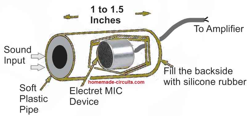
The microphone element is enclosed in a 1 to 1/2 inch length of lightweight plastic pipe, having silicone rubber filling the region behind the microphone.
The precise sizes are unimportant. The objective is to provide certain amount of directivity to the front of the microphone while isolating the rear.
Let's investigate a basic amplifier circuit now that we have a working pick-up device.
Circuit Description
The LM386 IC op-amp is still as good now as it was when it originally appeared several decades ago, and it is used in our first amplifier circuit in Fig. 2 below.
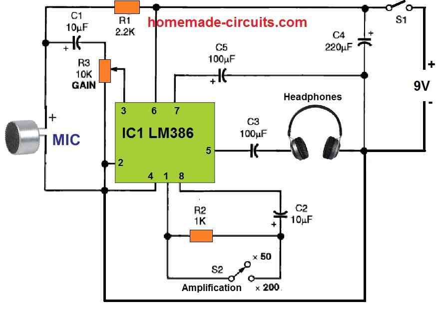
A section of shielded microphone wire connects the electret to the amplifier circuit. Make the cable length as little as feasible in case the microphone is used outdoors with the amplifier indoors.
The input of the amplifier is identical to that of an op-amp, comprising inverting and non-inverting inputs, a single output optimized to operate low impedance loads, and a gain adjust function.
Either inputs could be linked to circuit ground, resulting in a ground-referenced input. The amp operates on a 4 to 12 volt power supply and uses just under 30 mWs when not in use.
The maximal dissipation of the device is 660 mW. The only piece of advise I have for the amplifier's architecture is to keep the component lines short and the output wiring and components isolated from the input.
When utilizing S2's high gain level, carelessness would only produce creaks and squeaks. It's not easy to cope with, so try your best.
Sidenote: The above circuit can be also applied as a sensitive hearing aid circuit


Questions & Answers
An outdoor event here (British Columbia) had a board made up that has 8 bird sounds and the kid has to hit the right button to identify the correct name with the sound.
I don’t know what this circuit is called, hopefully there is a chip that can do this. I would love to make one for our organisation events (keeps.org)
your thoughts please, thank you, Michael Buckingham
Sounds very interesting. I will try to look for the chip, if I happen to find it, will update the circuit design here for you!