Whenever PWM is employed in an inverter for enabling a sine wave output, inverter voltage drop becomes a major issue, especially if the parameters are not calculated correctly.
In this website you might have come across many sine wave and pure sine wave inverter concepts using PWM feeds or SPWM integrations. Although the concept works very nicely and allows the user to get the required sine wave equivalent outputs, they seem to struggle with output voltage drop issues, under load.
In this article I have explained how to correct this through simple understanding and calculations.
First we must realize that output power from an inverter is merely the product of input voltage and current that's being supplied to the transformer.
Therefore here we must make sure that the transformer is correctly rated to process the input supply such that it produces the desired output and is able to sustain the load without any drop.
From the following discussion we'll try to analyze through simple calculations the method to get rid of this issue, by configuring the parameters correctly.
Analyzing Output Voltage in Square Wave Inverters
In a square wave inverter circuit we will typically find the waveform as shown below across the power devices, which deliver the current and voltage to the relevant transformer winding as per the mosfet conduction rate using this square wave:
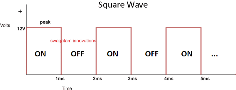
Here we can see that the peak voltage is 12V, and the duty cycle is 50% (equal ON/OFF time of the waveform).
To proceed with the analysis We first need to find the average voltage induced across the relevant transformer winding.
Supposing we are using a center tap 12-0-12V /5 amp trafo, and assuming 12V @ 50% duty cycle is applied to one of the 12V winding, then the average voltage induced within that winding and MOSFET drain can be calculated as given below:
12 x 50% = 6V
This also becomes the average voltage across the gates of the power devices, since the 50% duty cycle are applied to the MOSFET gates from the oscillator
For the two halves of the trafo winding we get, 6V + 6V = 12V (combining both the halves of the center tap trafo.
Multiplying this 12V with the full current capacity 5 amp gives us 60 watt
Now since the transformer actual wattage is also 12 x 5 = 60 watts, implies that the power induced at the primary of the trafo is full, and therefore the output will be also full, allowing the output to run without any drop in voltage under load.
This 60 watt is equal to the actual wattage rating of the transfomer, i.e. 12V x 5 amp = 60 watts. therefore the output from the trafo works with maximum force and does not drop the output voltage, even when a maximum load of 60 watt is connected.
Analyzing a PWM based Inverter Output Voltage
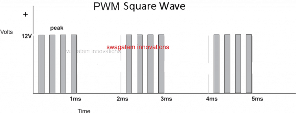
Now suppose we apply a PWM chopping across the gates of the power mosfets, say at a rate of 50% duty cycle on the gates of the mosfets ( which are already running with a 50% duty cycle from the main oscillator, as discussed above)
This again implies that the previously calculated 6V average is now impacted additionally by this PWM feed with 50% duty cycle, reducing the average voltage value across the mosfet gates to:
6V x 50% = 3V (although the peak is still 12V)
Combining this 3V average for both the halves of the winding we get
3 + 3 = 6V
Multiplying this 6V with 5 amp gives us 30 watts.
Well, this is 50% less than what the transformer is rated to handle.
Therefore when measured at the output, although the output might show a full 310V (due to the 12V peaks), but under load this might quickly drop to 150V, since the average supply at the primary is 50% less than the rated value.
To rectify this issue we have to tackle two parameters simultaneously:
1) We must make sure that the transformer winding matches the average voltage value delivered by the source using the PWM chopping,
2) and the current of the winding must be accordingly specified such that the output AC does not drop under load.
Let's consider our above example where the introduction of a 50% PWM caused the input to the winding to be reduced to 3V, to reinforce and tackle this situation we must ensure that the winding of the trafo must be correspondingly rated at 3V. Therefore in this situation the transformer must be rated at 3-0-3V
Current Specs for the Transformer
Considering th above 3-0-3V trafo selection, ans considering that the output from the trafo is intended to work with 60 watts load and a sustained 220V, we may need the primary of the trafo to be rated at 60 / 3 = 20 amps, yes that's 20 amps which the trafo will need to be to ensure that the 220V is sustained when a full load of 60 watt is attached to the output.
Remember in such situation if the output voltage is measured without a load, one might see a abnormal increase in the output voltage value which might appear to be exceeding 600V. This might happen because although the average value induced across the mosfets is 3V, the peak is always 12V.
But there's nothing to be worried about if you happen to see this high voltage without a load, because it would quickly settle down to 220V as soon as a load gets hooked up.
Having said this if users find it rattling to see such increased level of voltages without load, this can be corrected by additionally applying an output voltage regulator circuit which I have already discussed in one of my earlier posts, you may effectively apply the same with this concept also.
Alternatively, the raised voltage display can be neutralized by connecting a 0.45uF/600V capacitor across the output or any similarly rated capacitor, which would also help to filter out the PWMs into a smoothly varying sine waveform.
The High Current Issue
In the above discussed example we saw that the with a 50% PWM chopping, we are forced to employ a 3-0-3V trafo for a 12V supply, forcing the user to go for a 20 amp transformer just to get 60 watts, which looks quite unreasonable.
If 3V calls for 20 amps to get 60 watts, implies that 6V would require 10 amps to generate 60 watts, and this value looks quite manageable....... or to make it even better a 9V would allow yo to work with a 6.66 amp trafo, which looks even more reasonable.
The above statement tells us that if the average voltage induction on the trafo winding is increased, the current requirement is decreased, and since the average voltage is dependent on the PWM ON time, simply implies that to achieve higher average voltages on the trafo primary, you just have too increase the PWM ON time, that's another alternative and effective way to correctly reinforce the output voltage drop issue in PWM based inverters.
If you have any specified queries or doubts regarding the topic, you can always make use of the comment box below and jot in your opinions.


Questions & Answers
Thanks for the reply. Yes 4.7ohm resistor connect to 3 gates of the 3 MOSFETs (one for 3 MOSFETs). I will check the battery voltage when loaded and separately voltage regulation of the transformer.
Thanks.
Then it’s fine. Sure, you can check the battery and the transformer current delivery capacities.
Hi Swagatam,
I’m Dhammika from Sri Lanka, Colombo.
I’ve done an inverter circuit using EGS002 driver board for 500watt (totally using 12 IRF3205 MOSFETs). I’ve used one transformer.of the rating 100watt, 7.5V to 220V. The no load voltage is ok – primary side 8V and above and secondary voltage comes to around 220V ~ 230V.
But when loaded with a 100watt incandescent bulb voltage drops by 40V? Is this because of MOSFETS not biased correctly? I’ve used 4.7ohms series resistor to drive 3 parallel MOSFETs (connected and one 10K resistor between gate and the Sources). MOSFETs, transformer and the load connected in H bridge way, 3 MOSFETs x 4. Please let me know what to do in order to rectify. the voltage drop issue.
Thanks & Kind Regards,
Dhammika.
Hi Dhammika,
It is not due to the mosfets, it could be because of insufficient transformer and battrey current.
How did you connect the 4.7 ohm resistors in series? If these are the gate resistor of each mosfet then no issues, but if these resistors are connected anywhere else then it could be a problem, you must remove these series 4.7 ohm resistors.
Good day Mr.Swagatam, I made a high frequency inverter with sg3525,the output is 250v,but the MOSFET just gets too hot. What could be done to reduce or stop the heat
Hi Hillary, did you do the following? Also is the heating happening with load or without load?
Add a diode across the gate resistor.
Add a 1K resistor between gate and source of the mosfet.
The MOSFET gets too hot without load and I have done all you asked me to do
Then your mosfets are faulty, because the fault cannot be from the SG3525 pins, right? Try BJTs like TIP122 or TIP142 and check the response.
Good day Mr Swag.i made an inverter(full bridge) the output after the bridge is 6v but when connected to a transformer of VP=7v
Vs=230v
It just gives 28v.
Please what could be the reason for that
Good day sir, please how do I make a perfect filter circuit for my inverter output
Hello Hillary, I do not have the calculations for a perfect filter for inverter output. The easiest way is to add a high voltage capacitor across the output and alter its value until you get the best possible waveform.
Hello Hillary, Without checking the circuit it can be difficult for me to judge the fault. Most probably the MOSFETs are not conducting correctly or the bridge configuration itself might have problems.
I have a new Xantrex inverter charger 1800 for my boat. It puts out 120vac when using shore power. Without shore power and using the 12vdc battery it inverts only 96vac. It charges the battery just fine. Why only 96vac?
Is the 96V with load or without load? If its without load then probably the 12V from the battery is not enough to produce a 120V output. The shore power is probably generating more than 12V , which is causing the output also to increase proportionately.
My 12v batt bank, no load read 13v. 180ah. 240V 2000W inverter. When load is turned on, simple LED strip light the batt voltage drops to 9v. This is despite being connected to a smart battery charger. I suspect an inverter fault. However, any suggestions very welcome. The current draw for LED’s with battery bank full should not be draining batteries to 9v within half an hour.
Yes that seems to be an inverter fault. The inverter may be causing an over load or short circuit somewhere. LEDs cannot drain the battery to 9V, unless the battery is itself faulty.
You can try connecting an automotive lamp to the battery directly and check the results. If the battery voltage drops then it is the battery which may be faulty.
good day Mr swag. my question is, without using driver ICs is there any other way of achieving full bridge topology with ATmega328
Hillary, You can try BJT based full bridge driver as shown below, but IC is more recommended.
SG3525 Full Bridge Inverter Circuit
good evening swagatam, my question is, how do I increase or decrease the deadtime of sg3525 by the resistor
Hillary, a resistor between pin#7 and pin#5 of SG3525 IC determines the deadtime.
Hi, good day. I have an inverter with a center tapped transformer and would like to use same transformer as battery charger when there is power from grid. How do I go about it
Hillary, I have explained a relay based concept in the following article
https://www.homemade-circuits.com/single-transformer-inverterchargerchang/
good day swagatam. The question is how do I reduce the deadtime of sg3525? is it by reducing the resistor from pin#5 to pin#7 or by increasing it?
Increasing the resistance will increase the deadtime an vice versa.
good evening Mr swag. please is there a circuit diagram and program for inverter with Arduino
Yes I have one Arduino based inverter in this blog. You can find it here:
https://www.homemade-circuits.com/arduino-pure-sine-wave-inverter-circuit/
I must start by commending your good works and you time spent on replies.
My question is basically on the feedback circuit for sg3525 ic for inverter. Please a circuit diagram will be appreciated
Thank you Hillary, you can refer to the following post for understanding the feedback system in a SG3525 inverter circuit
https://www.homemade-circuits.com/inverter-circuit-with-feedback-control/
Good day Mr swag.
I have a question about ir2110 and tlp250 drivers. My question is, does the both of them have internal dead time. Please explain both of them explicitly
Hello Hillary,
IR2110 has an internal deadtime, but TLP250 is an opto coupler, so deadtime is not relevant to this IC.
Thank you so much,secondly,does topology (h ridge or push pull) have any effect on the wave form of an inverter?
The waveform will be always square wave no matter which topology is used. The square wave can be converted to sine wave only through an external SPWM chopping circuit.
What is this external chopping circuit? And a circuit diagram will do a lot of explaination for me please
You can refer to these articles;
https://www.homemade-circuits.com/how-to-modify-square-wave-inverter-into/
https://www.homemade-circuits.com/simple-ic-555-inverter-circuit/
https://www.homemade-circuits.com/sg3525-pure-sinewave-inverter-circuit/
Good day sir, I have been working on an inverter with Arduino but always having either a damaged MOSFET or driver(ir2110)
Hi Hillary, first build the IR2110 inverter separately without Arduino and check whether this inverter works or not….if it does then integrate the Arduino with it. This process will help you to understand which circuit stage is actually causing the problem.
Good day Mr swag, when using center tap transformer for sine wave inverter, does it have negative effect on the wave
Hi Hillary,
No, I don’t think a center tap transformer can have a negative effect on the sine waveform
I have built one with sg3525 and once linked with the MOSFET it stays for a while and the driver gets damaged too
You must first check whether the SG3525 is producing the required frequency or not, and also make sure the MOSFETs are original and good.
Good day Mr. Swagatam. I have 4pieces of tlp250 and want to use it as MOSFET driver for an inverter but the problem is the microcontroller only has 2 outputs and the tlp250 are 4.how do I go about it?
Hi Hillary,
You can connect the TLP250 with the MOSFET in the following manner, repeat this for both the mosfets.
Good day Mr. Swag, I only have 2 outputs and the configuration needs 4 outputs. How do I do it
Hillary, please see the previous diagram, let me know what difficulty you are having with this configuration.
The thing is, I want to use it in h-bridge topology and I need 4 pieces of tlp250 to do that. My problem now is, how do I drive these 4tlp250 with just 2 pwm output from microcontroller
You should have mentioned the H-bridge before. Making an H-bridge with 4 optocouplers and 2 inputs is extremely difficult.
However the opto couplers are simply not required if a good H-bridge driver IC is utilized
Hi Swagatam. I removed the feedback from the Circuit. On each side, the gate voltage was 5v (that is, the voltage from either pin 11 or pin 14 was 5v each.)
Here’s my question.
1) Is the voltage on either pin 11 or 14 when measured as you directed me using a voltmeter, supposed to be 12v each?
If yes then please drop a link to a driver circuit using sg3524 as the ic for me which would produce 12v on either sides. I’d then make use of your driver circuit.
Thanks.
Hi Chria,
They will be 12V, but since the outputs of the IC are oscillating at 50% duty cycle, the average output voltage measured across these pinouts will be 6V. It could be also 5V because of 1 V lost in the deadtime setting.
You can confirm the 12V by adding a diode on one of the output pins followed by a 10uF capacitor across the diode’s cathode and the ground line. Measure the voltage across this capacitor and you will find it to be 12V.
You mentioned adding a diode and a capacitor.
Can i include this diode and capacitor in my actual inverter circuit? Would it improve the output of my inverter?
No, this is only to confirm that you are getting a 12V peak at the outputs of the IC….please do not do this with the mosfet gates, otherwise the mosfets will blow of instantly.
Thanks a lot for your quick response. Without the feedback, i was able to get 5v across the outputs. From your explanation above, it means 5+5=10v. So to harness the full power from my driver, am i adviced to use a 10-0-10 transformer while still using a 12volt battery?
You are right, if the gate voltages are around 10V, then you must use a transformer rated at slightly less primary voltage than 10V, a 9-0-9V will be much suitable.
Hi. Please how do i measure the voltage across the gates of my mosfet?
I’m using an sg3524 ic as my driver.
Thanks.
Thanks a lot Swagatam.
I measured the gate voltage it and i got about 4.67v maximum on both sides. And by adjusting the variable resistor that controls the feedback, the gate voltage varied but i got 4.67v maximum.
My question here is.
Is there anyway i can increase this gate voltage to about 6v or slightly higher because, i experience a slight voltage drop when i apply a load across the transformer’s output.
I’m using a 12-0-12v transformer.
I’m using sg3524 ic as my driver.
Thank you
Hi Chris, what you are seeing is the average DC on the gates because the feedback is consistently trying to suppress the mosfet conduction. You can try increasing the feedback threshold and then measure the gate voltage, or you can temporarily remove the feedback and then check the gate voltage and you will find it to be 12V, because the output from the SG3524 will be always equal to its Vcc supply Dc value
It can be measured using a voltmeter, touch the positive probe on the gate, and the negative probe on the source.
good morning sir,this is really interested.my question is: can i combine both pwm and output voltage correctio to further strengthen the inverter against voltage drop?
Thanks yusuf,
you can prevent over voltage, but you cannot prevent a voltage drop due to over load, no matter what correction circuit you use. If your inverter voltage is dropping below a minimum level, it means either your battery is discharged below the required level, or the load has exceeded the maximum specified level.
With a constant PWM from the inverter there’s no need of an extra voltage correction circuit, according to me.
HI,, Cottage country, I have an off grid 1500 watt inverter ( 110 volts 60 Hz), with plenty of battery power over 1000 amps available, yes, lots of power available.
I have connected a small bar fridge, 150 watts, and when the fridge starts the lights ( 3 LED light bulbs 10 watt each) dim for a split second and then all is normal, no problems there, and it’s expected because of a small voltage drop due to the fridge compressor start up surge.
I can leave with that.
Here is what I don’t quite get it yet:
I also have a small 15 watt LTE 4 G Router ( runs on a little SMPS 90 to 240 VAC to 12 volts DC) Big deal..lol
Here is the problem: if and when I plug my laptop power supply ( also SMPS 90 to 240 VAC), the router reboots as if the voltage dropped below a preset value, and it happens whether the fridge is running or not, and the fridge is not affected. Switch mode power supply, seams not to like the inverter or vise versa..lol
My suggestion to fix this to install this device at the output of the inverter, an EMI filter DFC-2715R rated to 250 VAC at 15 Amps AC, that may be sufficient to keep the voltage value steady for a few milliseconds, when an SMPS is connected, because it’s the only time that other devices powered by SMPS will reboot, whatever is running on SMPS will resart, regardless how small of its power consumption.
Even my small LEDTV 45 watts reboots because it has a built in SMPS.
My system is not overloaded, I am way below the inverter power, and not all items are plugged at the same time, believe me, it’s these crazy SMPS that are creating havoc.
Please give me your opinion on my idea, and do not answer back with a lot of questions that you can extrapolate from this text. The inverter is properly grounded and as long as I don’t have any SMPS units plugged it, all is fine..and still is, except some will reboot as I explained above.
A friend has a 10 KVA inverter ( also off grid ) and the same happens..lol
I think I will install that EMI filter at the output of the inverter, what do you think?
ed
Yes please install the EMI with some additional large capacitors, that might possibly solve the problem.
Thanks, Mr Swagatam, for your generosity in passing knowledge. Please, my question is: does the automatic voltage regulator for an arduino sinewave inverter you discussed about in your other post for controlling high output voltages in the case for a charged battery control the output voltage drop when load is applied?
Chinedu, the voltage regulator circuit will only prevent a high voltage output, but will not prevent a low voltage, because the low voltage would indicate over load situation and lack of battery power to tackle the load, which cannot be compensated by any means.
Hi, thank you first of all for all the information. My question. I build a small inverter with a 4047ic as the multivibrator, 2 x IRF3205 mosfets. So when i apply 12v 7.2ah battery i see that my outputs on the ic(pin 10 & 11) is around 6.5v. So i used a 12-0-12v transformer. When i apply a 48w Lcd tv the 220ac voltage drop to 180ac. My output is a 50% duty cycle at around 51hz, Square wave.
Q. Should my transformer be 6-0-6, or if i put 24v dc with a 7812 voltage regulator to protect the ic can i then keep the 12-0-12 transformer and will that improve my inverter output.
Q. Please can you recommend what i should do to juice up the watts.
Q. if i understand you correctly from the above diagram a full bridge is much more efficient than my push pull circuit. If that is the case then i will try to build the circuit. Just 2 questions.
Q. At the primary there is no center tap
Q. The IRF9540’s in your diagram not all the gates seems to be connected.
Thank you very much for all your input.
Peter Ferreira
South Africa
Hi, your first assumption regarding the transformer, battery is absolutely correct.
To increase the current you will have to increase the wire thickness of the transformer, and accordingly increase the battery Ah rating.
Full bridge is definitely more efficient, and it will require a 2 wire primary between the MOSFETs, a center tap is not required.
The gates of the p channel MOSFETs are connected in parallel with each other, just like their drain and the source terminals.
Good day Sir;
Thank you for your invaluable Tech. guides,i appreciate.This voltage drop address is a very important issue.I just watched a video on Youtube on which the host uses two 555 ic to create pulses ,one astable and the other Monostable.He then passes the astable pulses to the monostable ic and with the help of variable resistor to generate duty circle of any percentage.Can you open-up on this.There was no circuit—only schematic he gave.
From your analyses of voltage drop due to low duty circle from 12v to 3v on transit of sq wave to pwm,is it good if i use a 48v transformer so that it narrows down to 12v which is the normal dc voltage,or do i have to rewind my 12v transformer to 6v or 3v for proper matching?.
I have some transformers in which the input and output voltage is written but lacks the current and power rating,like—(1) 220/15-0-15…..(2) 120-012 (3) 6.8-0-6.8. Number (2) and (3) presumably from 1200kva or 800kva ups. Can one use a guessed current for calculation?
What do you suggest on these issues above.
Thank You.
Thank you Patrick,
It was probably me who ws the first person to have implemented the IC 555 based SPWM in an inverter, here’s the diagram:
for the detailed explanation you can refer to the last two concepts under this post:
https://www.homemade-circuits.com/modified-sine-wave-inverter-circuit-2/
For the transformer selection, the rule of thumb is, its primary should be equal to the average DC value which is measured at the gates of the driver MOSFETs
I would like some advice please.
I bought a sma sunny boy 2 and 4 400 watt panels.
Installing myself complete because of covid problem no sparkies.
All was well until inverter stopped working most mornings between 0830 to 10 ish.
I realized the the rice mill a few hundred yards from my farm was running.
Hence our bad voltage drop.
The equipment supplier said talk to your electricity supplier.
I know before I start this will be a battle, it took 4 years just get electricity here.
So is there other options I can persue.
Look forward to any help you may have.
Thank you.
The easiest option is to buy a 500 watt inverter and hook it up with your solar panel and use it during the low voltage periods. Or if you are well versed with building inverters and basic electronic concepts you can select an appropriate design from this website and do it yourself.
Dear Swagatam,
I would like to know what to do and how to implement an EFFICIENT DRIVER circuit,
with BJT trasistors, because I am not able to implement this with IR´S
because all the examples that I found here on the internet, teach only how to avoid with the IR´S
for the “H” BRIDGE system, and the system I’m thinking of creating is of the type: PUSH-PULL
In this way I found nothing teaching how to dodge with the IR´S, for this system that I will use
Could you help me ? if so, the information would be the following:
– SG3525 PWM = 5V 60hz square wave, I want to increase this voltage level and obviously current tb to about 10 to 12V voltage and current enough to generate 20 IRF640 mosfet´s, 10 per ARM that I will use on my inverter… ..
I hope you can help me with my problem….
Dear Endel, if you want a fail proof efficient N channel based full bridge topology, then you must go for a specialized IC based design such as using IRS.
Alternatively you can go for P and N channel combination as shown below. But this may require many p channel MOSFETs, although the design is very easy implement.
I do not want anything with FULL BRIDGE dear friend, but with push pull, because I do not like this topology of FULL BRIDGE, I prefer PUSH PULL, because here in Brazil my country, the power is 110vac and not 220vac, we do not have much energy … so I prefer the push pull system, would you have any examples with IR drivers for the push pull system please dear friend
Hi, a full bridge is specifically a push-pull design. There’s no better push-pull design than a full bridge. A center tap version is also push pull, but it uses two winding at the primary and is less efficient than full bridge.
hello. I builded a pure sine wave inverter which based on spwm signals. power supply is 18.5V Dc and the rms voltage of the primary of transformer is approximately 9V. The transformer has 15-0-15-400 on primary and 0-230V on secondery windings. Im usin 15-0 port of the transformer. The power of the transformer is 100VA/321VA . Without any load i can see the 220V RMS voltage on the output.When i plug the load (25W bulb) the voltage decreasing about 90VRMS. Why this is happening ?? I have also tried another loads but it is the same. Need help here !
Hello, if the transformer primary is 15-0-15V then this voltage is the RMS of the transformer primary, not 9V.
Your inverter output is dropping because the power supply which are using instead of a battery does not have sufficient current. Use a 10 amp SMPs or a battery for the power supply and then you will find the output behaving consistently.
Good day sir, please can I see an mppt charge controller circuit
Hi Hillary, you may refer to the following post:
https://www.homemade-circuits.com/homemade-solar-mppt-circuit-maximum/
I have issues with my Magnavox Inverter on a solar PV system. When my water pump kicks in (when a tap is turned on) the voltage drops off and appliances such as oven, washing machine (anything that has a circuit board controller) cutout and either need resetting or if the washer is in a cycle it will restart the cycle from scratch. HELP?!
You will need an additional 100 Ah battery working in parallel with the PV system, this battery will compensate the extra power needed during the pump switch ON, and could be disconnected as soon as the pump has started.
Hi
Pleas if you can find copy in arbic , that is we wont to understand it.
Hi, I think Google has English to Arabic translation, which you can use!!
I made 500w modifisinwave inverter. I want to run my 150w refrigerator.but I can”t it.because volatage drop 160v . I use 200ah two batteries connect parrell.please help me solve this problem. forgive me my poor english.
A correctly built 500 watt inverer will never drop its voltage when loaded with 150 watt. Your battery rating is OK no doubt, may be your transformer is not OK. It could be rated at much lower wattage than 500 watts,you must get it checked from a professional trafo designer.
For the battery even a single 200Ah should be more than enough to handle the 150 watt, even with the initial surge.
You may also want to confirm if your refrigerator is actually consuming 150 watt or much more than that??
Hello,
I thankful to you to encourage the people to do things better and better,
I need your help, Pls suggest its my request,
Question 01. If i want the output is 5000w pure sine wave inverter require but i have only 500w Transformer 10 nos in my hand, can i use the transformers parallel or series in single circuit to get output 5000w ?
Question 02: can i use single oscillator and driver circuit to drive multiple output mosfet drive possible, pls explain. Note : One oscillator and driver to drive output point mosfet and 10 nos separated 500w transformers .
thanks and regards
Moha
Hello Moha, yes you can connect the primary wires in parallel but not the output secondary wires…you may terminate the outputs to different sockets and to separate loads.
yes you can use a single oscillator circuit for driving different mosfets configured with different transformers….but make sure to connect all their negative lines in common.
In my thinking, for 12v input to avoid voltage drop, why can’t we increase the voltage and make the trafo 24v-0-24v so that pwm will be 6v.
nice article, I really appreciate it, I will like you to do a tutorial on ups/inverter transformer. Am really impressed with it’s charging and regulating future, and will really like you to feature it.
Thanks again for all you support.
Ok, but if you run mains voltage into another turns in the secondary side of the transformer (with correct amount of turns) wouldn’t it no affect the primary side of the transformer which is linked the mosfets and stuff?
Considering SG3225 inverter circuit and automatic change over…
Thanks a lot, really appreciate all the work you have put to your listeners.
Thanks Miebaka
yes it will affect, the mosfet side will need to be simultaneously cut off while this is changeover is implemented.
Thanks Miebaka, according to me there’s no difference between an inverter transformer and an UPS transformer, a transformer is designed for transforming a given voltage from one level to another through mutual induction, which is the same in inverers and UPSs
Hello Sir i am Farhan
I have a 100 watt inverter
I also have a AC led tube light of 18 watt
I want to connect them like qhen i press the Light switch on
Then it will run on main Ac current
And when the ac line gone
Light will be connected with the inverter line
Thanx
Hi Farhan,
you can do it by wiring a relay appropriately…. simply connect the coil of a DPDT relay or two SPDT relays with a DC supply obtained from mains input, then connect the N/C contacts of the relay with the inverter AC, N/O contacts with the mains AC, and the poles with the LED
Pattern of flashing can be according to your wish sir…only thing is that it should look attractive…
OK, let me try!
Thanks but please check your mail..I attached a picture..
your sent design is a PIC based so I could not interpret its functioning details, and therefore could not solve your query.
Building a non center tap transformer for pure sine wave.. And battery is 24v.. Therefore the required primary volt is 14v..and secondary 240v.. What if the primary volt is less than 14 or more than 14? Will there be error or something? Using TPV formula
for 24V supply, the trafo primary must be also around 24V…unless PWM is being is used…it cannot be 14V
slightly higher supply will not affect the trafo performance but if it's significantly high then the trafo will begin heating up, and the 220v output will also proportionately get high…for the low voltages the transformer will not heat up, but the output will drop proportionately
Hello sir, Iam working on a project to build an inverter charger with pwm using a non centre tap transformer. I have tried an 18-0-18 transformer it’s working but with charging it’s very slow. I had to increase the transformer voltage to 20-0-20 and connected a bridge diode to test charging speed and it’s just wow,now am yet to connect it to the mosfets and try out if it will still deliver/mosfets might go boom? Pliz help me know if this idea is ok? Or what changes needed? I will really appreciate.
Hi Evans, without seeing the schematic or understanding the working of the circuit it can be difficult to suggest anything. Are you using the same transformer for inverter and battery charging both?
Yes sir,am using the same transformer for inverter and charging.
Hi,with the example above (for 60w using 3v transformer will require a 20 amp transformer which is cost) but using a 9v transformer will call for a less amp transformer hence much cheaper ,Will the use of a 20v transformer for a 24v be ok for a pwm?
Hi, You will have to calculate it as explained in the above article
Sir,do you have simple circuit of led cube without arduino or ic programming
I tried but it looks difficult, and might require much thinking, by the way you can specify the pattern of the flashing/chasing that you want across the grids, if it seems feasible I may try again.
ok sir..waiting
OK,I'll try to design it, but the sequencing will be as per the convenience of the design, with minimum complexity…
sir,i want the leds to be flashing and running
NVD, if it's a solid cube that you want, then that can be simply done by connecting the LEDs in series/parallel. MCU won't be required
thanks for the gud work you do to help us
you are welcome!
okay Thanks.
thumbs up!
Thanks for sharing
so it is recommended to choose a lower voltage high amp transformer the the input volts . eg. if you input is a 12v battery will be good to choose 7-10v for the inverter.
…it must be implemented as per the calculation presented in the article
Thanks, yes that's correct according to my assumptions.