Whenever PWM is employed in an inverter for enabling a sine wave output, inverter voltage drop becomes a major issue, especially if the parameters are not calculated correctly.
In this website you might have come across many sine wave and pure sine wave inverter concepts using PWM feeds or SPWM integrations. Although the concept works very nicely and allows the user to get the required sine wave equivalent outputs, they seem to struggle with output voltage drop issues, under load.
In this article I have explained how to correct this through simple understanding and calculations.
First we must realize that output power from an inverter is merely the product of input voltage and current that's being supplied to the transformer.
Therefore here we must make sure that the transformer is correctly rated to process the input supply such that it produces the desired output and is able to sustain the load without any drop.
From the following discussion we'll try to analyze through simple calculations the method to get rid of this issue, by configuring the parameters correctly.
Analyzing Output Voltage in Square Wave Inverters
In a square wave inverter circuit we will typically find the waveform as shown below across the power devices, which deliver the current and voltage to the relevant transformer winding as per the mosfet conduction rate using this square wave:
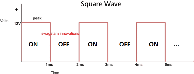
Here we can see that the peak voltage is 12V, and the duty cycle is 50% (equal ON/OFF time of the waveform).
To proceed with the analysis We first need to find the average voltage induced across the relevant transformer winding.
Supposing we are using a center tap 12-0-12V /5 amp trafo, and assuming 12V @ 50% duty cycle is applied to one of the 12V winding, then the average voltage induced within that winding and MOSFET drain can be calculated as given below:
12 x 50% = 6V
This also becomes the average voltage across the gates of the power devices, since the 50% duty cycle are applied to the MOSFET gates from the oscillator
For the two halves of the trafo winding we get, 6V + 6V = 12V (combining both the halves of the center tap trafo.
Multiplying this 12V with the full current capacity 5 amp gives us 60 watt
Now since the transformer actual wattage is also 12 x 5 = 60 watts, implies that the power induced at the primary of the trafo is full, and therefore the output will be also full, allowing the output to run without any drop in voltage under load.
This 60 watt is equal to the actual wattage rating of the transfomer, i.e. 12V x 5 amp = 60 watts. therefore the output from the trafo works with maximum force and does not drop the output voltage, even when a maximum load of 60 watt is connected.
Analyzing a PWM based Inverter Output Voltage
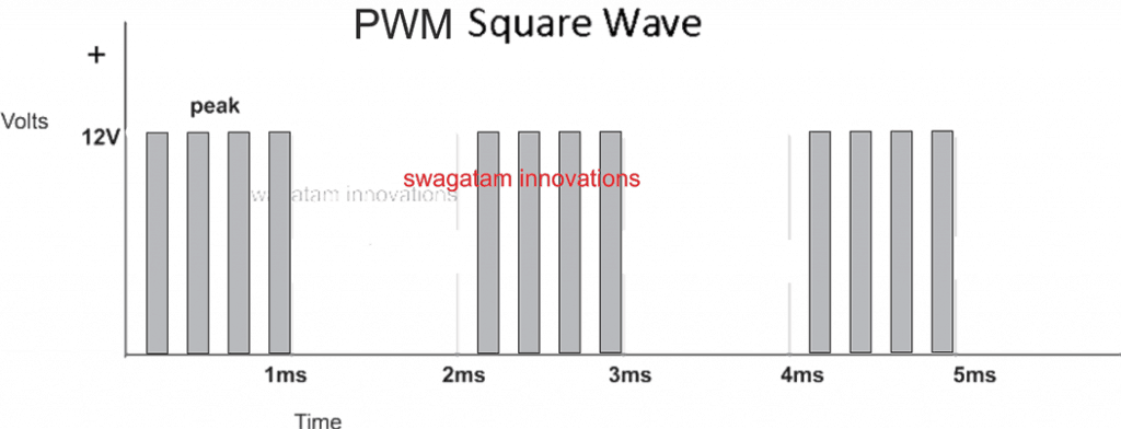
Now suppose we apply a PWM chopping across the gates of the power mosfets, say at a rate of 50% duty cycle on the gates of the mosfets ( which are already running with a 50% duty cycle from the main oscillator, as discussed above)
This again implies that the previously calculated 6V average is now impacted additionally by this PWM feed with 50% duty cycle, reducing the average voltage value across the mosfet gates to:
6V x 50% = 3V (although the peak is still 12V)
Combining this 3V average for both the halves of the winding we get
3 + 3 = 6V
Multiplying this 6V with 5 amp gives us 30 watts.
Well, this is 50% less than what the transformer is rated to handle.
Therefore when measured at the output, although the output might show a full 310V (due to the 12V peaks), but under load this might quickly drop to 150V, since the average supply at the primary is 50% less than the rated value.
To rectify this issue we have to tackle two parameters simultaneously:
1) We must make sure that the transformer winding matches the average voltage value delivered by the source using the PWM chopping,
2) and the current of the winding must be accordingly specified such that the output AC does not drop under load.
Let's consider our above example where the introduction of a 50% PWM caused the input to the winding to be reduced to 3V, to reinforce and tackle this situation we must ensure that the winding of the trafo must be correspondingly rated at 3V. Therefore in this situation the transformer must be rated at 3-0-3V
Current Specs for the Transformer
Considering th above 3-0-3V trafo selection, ans considering that the output from the trafo is intended to work with 60 watts load and a sustained 220V, we may need the primary of the trafo to be rated at 60 / 3 = 20 amps, yes that's 20 amps which the trafo will need to be to ensure that the 220V is sustained when a full load of 60 watt is attached to the output.
Remember in such situation if the output voltage is measured without a load, one might see a abnormal increase in the output voltage value which might appear to be exceeding 600V. This might happen because although the average value induced across the mosfets is 3V, the peak is always 12V.
But there's nothing to be worried about if you happen to see this high voltage without a load, because it would quickly settle down to 220V as soon as a load gets hooked up.
Having said this if users find it rattling to see such increased level of voltages without load, this can be corrected by additionally applying an output voltage regulator circuit which I have already discussed in one of my earlier posts, you may effectively apply the same with this concept also.
Alternatively, the raised voltage display can be neutralized by connecting a 0.45uF/600V capacitor across the output or any similarly rated capacitor, which would also help to filter out the PWMs into a smoothly varying sine waveform.
The High Current Issue
In the above discussed example we saw that the with a 50% PWM chopping, we are forced to employ a 3-0-3V trafo for a 12V supply, forcing the user to go for a 20 amp transformer just to get 60 watts, which looks quite unreasonable.
If 3V calls for 20 amps to get 60 watts, implies that 6V would require 10 amps to generate 60 watts, and this value looks quite manageable....... or to make it even better a 9V would allow yo to work with a 6.66 amp trafo, which looks even more reasonable.
The above statement tells us that if the average voltage induction on the trafo winding is increased, the current requirement is decreased, and since the average voltage is dependent on the PWM ON time, simply implies that to achieve higher average voltages on the trafo primary, you just have too increase the PWM ON time, that's another alternative and effective way to correctly reinforce the output voltage drop issue in PWM based inverters.
If you have any specified queries or doubts regarding the topic, you can always make use of the comment box below and jot in your opinions.


Questions & Answers
Thanks for the reply. Yes 4.7ohm resistor connect to 3 gates of the 3 MOSFETs (one for 3 MOSFETs). I will check the battery voltage when loaded and separately voltage regulation of the transformer.
Thanks.
Then it’s fine. Sure, you can check the battery and the transformer current delivery capacities.
Hi Swagatam,
I’m Dhammika from Sri Lanka, Colombo.
I’ve done an inverter circuit using EGS002 driver board for 500watt (totally using 12 IRF3205 MOSFETs). I’ve used one transformer.of the rating 100watt, 7.5V to 220V. The no load voltage is ok – primary side 8V and above and secondary voltage comes to around 220V ~ 230V.
But when loaded with a 100watt incandescent bulb voltage drops by 40V? Is this because of MOSFETS not biased correctly? I’ve used 4.7ohms series resistor to drive 3 parallel MOSFETs (connected and one 10K resistor between gate and the Sources). MOSFETs, transformer and the load connected in H bridge way, 3 MOSFETs x 4. Please let me know what to do in order to rectify. the voltage drop issue.
Thanks & Kind Regards,
Dhammika.
Hi Dhammika,
It is not due to the mosfets, it could be because of insufficient transformer and battrey current.
How did you connect the 4.7 ohm resistors in series? If these are the gate resistor of each mosfet then no issues, but if these resistors are connected anywhere else then it could be a problem, you must remove these series 4.7 ohm resistors.
Good day Mr.Swagatam, I made a high frequency inverter with sg3525,the output is 250v,but the MOSFET just gets too hot. What could be done to reduce or stop the heat
Hi Hillary, did you do the following? Also is the heating happening with load or without load?
Add a diode across the gate resistor.
Add a 1K resistor between gate and source of the mosfet.
The MOSFET gets too hot without load and I have done all you asked me to do
Then your mosfets are faulty, because the fault cannot be from the SG3525 pins, right? Try BJTs like TIP122 or TIP142 and check the response.
Good day Mr Swag.i made an inverter(full bridge) the output after the bridge is 6v but when connected to a transformer of VP=7v
Vs=230v
It just gives 28v.
Please what could be the reason for that
Good day sir, please how do I make a perfect filter circuit for my inverter output
Hello Hillary, I do not have the calculations for a perfect filter for inverter output. The easiest way is to add a high voltage capacitor across the output and alter its value until you get the best possible waveform.
Hello Hillary, Without checking the circuit it can be difficult for me to judge the fault. Most probably the MOSFETs are not conducting correctly or the bridge configuration itself might have problems.
I have a new Xantrex inverter charger 1800 for my boat. It puts out 120vac when using shore power. Without shore power and using the 12vdc battery it inverts only 96vac. It charges the battery just fine. Why only 96vac?
Is the 96V with load or without load? If its without load then probably the 12V from the battery is not enough to produce a 120V output. The shore power is probably generating more than 12V , which is causing the output also to increase proportionately.
My 12v batt bank, no load read 13v. 180ah. 240V 2000W inverter. When load is turned on, simple LED strip light the batt voltage drops to 9v. This is despite being connected to a smart battery charger. I suspect an inverter fault. However, any suggestions very welcome. The current draw for LED’s with battery bank full should not be draining batteries to 9v within half an hour.
Yes that seems to be an inverter fault. The inverter may be causing an over load or short circuit somewhere. LEDs cannot drain the battery to 9V, unless the battery is itself faulty.
You can try connecting an automotive lamp to the battery directly and check the results. If the battery voltage drops then it is the battery which may be faulty.
good day Mr swag. my question is, without using driver ICs is there any other way of achieving full bridge topology with ATmega328
Hillary, You can try BJT based full bridge driver as shown below, but IC is more recommended.
SG3525 Full Bridge Inverter Circuit
good evening swagatam, my question is, how do I increase or decrease the deadtime of sg3525 by the resistor
Hillary, a resistor between pin#7 and pin#5 of SG3525 IC determines the deadtime.
Hi, good day. I have an inverter with a center tapped transformer and would like to use same transformer as battery charger when there is power from grid. How do I go about it
Hillary, I have explained a relay based concept in the following article
https://www.homemade-circuits.com/single-transformer-inverterchargerchang/
good day swagatam. The question is how do I reduce the deadtime of sg3525? is it by reducing the resistor from pin#5 to pin#7 or by increasing it?
Increasing the resistance will increase the deadtime an vice versa.
good evening Mr swag. please is there a circuit diagram and program for inverter with Arduino
Yes I have one Arduino based inverter in this blog. You can find it here:
https://www.homemade-circuits.com/arduino-pure-sine-wave-inverter-circuit/
I must start by commending your good works and you time spent on replies.
My question is basically on the feedback circuit for sg3525 ic for inverter. Please a circuit diagram will be appreciated
Thank you Hillary, you can refer to the following post for understanding the feedback system in a SG3525 inverter circuit
https://www.homemade-circuits.com/inverter-circuit-with-feedback-control/
Good day Mr swag.
I have a question about ir2110 and tlp250 drivers. My question is, does the both of them have internal dead time. Please explain both of them explicitly
Hello Hillary,
IR2110 has an internal deadtime, but TLP250 is an opto coupler, so deadtime is not relevant to this IC.
Thank you so much,secondly,does topology (h ridge or push pull) have any effect on the wave form of an inverter?
The waveform will be always square wave no matter which topology is used. The square wave can be converted to sine wave only through an external SPWM chopping circuit.
What is this external chopping circuit? And a circuit diagram will do a lot of explaination for me please
You can refer to these articles;
https://www.homemade-circuits.com/how-to-modify-square-wave-inverter-into/
https://www.homemade-circuits.com/simple-ic-555-inverter-circuit/
https://www.homemade-circuits.com/sg3525-pure-sinewave-inverter-circuit/
Good day sir, I have been working on an inverter with Arduino but always having either a damaged MOSFET or driver(ir2110)
Hi Hillary, first build the IR2110 inverter separately without Arduino and check whether this inverter works or not….if it does then integrate the Arduino with it. This process will help you to understand which circuit stage is actually causing the problem.
Good day Mr swag, when using center tap transformer for sine wave inverter, does it have negative effect on the wave
Hi Hillary,
No, I don’t think a center tap transformer can have a negative effect on the sine waveform
I have built one with sg3525 and once linked with the MOSFET it stays for a while and the driver gets damaged too
You must first check whether the SG3525 is producing the required frequency or not, and also make sure the MOSFETs are original and good.
Good day Mr. Swagatam. I have 4pieces of tlp250 and want to use it as MOSFET driver for an inverter but the problem is the microcontroller only has 2 outputs and the tlp250 are 4.how do I go about it?
Hi Hillary,
You can connect the TLP250 with the MOSFET in the following manner, repeat this for both the mosfets.
Good day Mr. Swag, I only have 2 outputs and the configuration needs 4 outputs. How do I do it
Hillary, please see the previous diagram, let me know what difficulty you are having with this configuration.
The thing is, I want to use it in h-bridge topology and I need 4 pieces of tlp250 to do that. My problem now is, how do I drive these 4tlp250 with just 2 pwm output from microcontroller
You should have mentioned the H-bridge before. Making an H-bridge with 4 optocouplers and 2 inputs is extremely difficult.
However the opto couplers are simply not required if a good H-bridge driver IC is utilized