The EGS002 board is nothing but a combination of a microcontroller with a H-bridge driver like the IR2110. So if you are interested to build your own EGS002 equivalent board with exactly identical features, then you can do it using the instructions given in the following article.
So, here we are trying to build our own version of that popular EGS002 sine wave inverter module. But this one we will make using Arduino, and we will feed SPWM directly to a dual IR2110 based full H-bridge MOSFET driver.
And yes, we also got one opto coupler feedback section added for over voltage cut off safety. The whole thing looks solid and should work very close to EGS002.
Let us go step by step and understand how we have built it and how you can build this one too.
How It Works Like EGS002
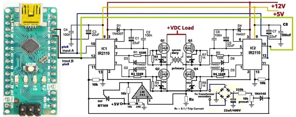
In middle of circuit we have four MOSFET switches, Q1, Q2, Q3, Q4. They make H-bridge. This H-bridge job is very simple, it change DC power to AC power by shaking voltage inside transformer primary.
Since we want to drive these MOSFET nicely so now we use two IR 2011 driver chips. These chips are too much important. Why? Because if you want to turn on top MOSFETs Q1 and Q3, then you need big voltage, much higher than main DC power. But do not worry, the chip does this trick easily with bootstrap parts. Let us see diode D1, D4 and capacitor C1, C2. When low side switch turn on, then these parts together make extra floating voltage. So now, top MOSFETs get full power and staying cold.
Now, look at Input A and Input B signals. They come straight from your microcontroller like Arduino pin 8 and 9. Or you can also feed these input signals from an SG3525 pwm IC outputs, or an TL494 PWM outputs, or simply from the IC 4047.
These signals talk to each other and tell the switches when to turn on and off so current can flow.
In power electronics, safety is so crucial. If you look very close at MOSFET gates, then you will see small resistors and diodes there.
Resistors R1, R2, R5, R6 are 150-ohm. They stop big initial current spike when gate is filling up, so no bad noise happens. Next to them, we put fast 1N4007 diodes, D2, D3, D5, D6. When switch turn off, then these diodes quickly empty the gate, so power is not wasted and switches do not crash together.
Also every gate has 15-volt Zener diode and 1k resistor. This makes sure voltage never goes too high, so your expensive switches do not get damage from bad noise.
But why this circuit is better than cheap ones? Because it has hardware protection inside.
Over Current Overload Protection
First, let us see over-current shut down. At the bottom, we put small resistor Rs near ground. Since load draws current, so voltage goes through Rs. So an equivalent voltage is developed across Rs, proportional to the load current. This voltage goes into pin 3 of LM393 chip.
If you want to know resistor value, then you calculate: Rs = 0.1/Max Trip Current (in Amps)
The output of the LM393 feeds the gate of an SCR network using BT169 SCR...
When SCR turns on then it pulls up shutdown pins of both IR 2011 ICs to +5V. Since SCR get latched instantly, then it shuts off the H-bridge immediately so nothing blows up. The system stays dead until you clear problem and restart power.
Over Voltage Feedback Protection
Second, we have over-voltage feedback. We take sample from transformer secondary, put it in bridge rectifier, filter with 22-microfarad capacitor, and tune it with 10k preset. That signal goes through 1N4148 diode straight to the shutdown pin 11 of the IR2110 Ics.
When a high voltage happens and exceeds 1V, it causes the SD pins to get activated and then the shut down of the ICs and the MOSFETs is triggered.
This continuous ON OFF triggering of the SD pins keeps the output voltage within the safe set limts.
Construction Steps
- Take a clean double-sided PCB or general purpose board.
- First place and solder both IR2110 ICs with all boot capacitors, diodes, resistors.
- Connect the MOSFETs close to the IR2110s using thick tracks or wires.
- Keep Arduino mounted on a separate PCB and connect pins D9–D12 to IR2110 HIN, LIN pins.
- Give 12V to IR2110, 5V to Arduino.
- Build the output LC filter if needed (optional).
- Add opto coupler circuit on output side with series 100 ohm and preset.
- Check and test everything with small DC input first.
Download Arduino SPWM Code:
// SPWM code for Arduino Nano Inverter (50Hz output)
// Uses Hardware Timer 1 on Pins 9 and 10 at ~31.3 kHz switching frequency

const int steps = 20;
// A true half-sine wave lookup table (0 to 255 to 0)
const byte sineTable[20] = {
  0, 40, 79, 117, 153, 185, 213, 235, 249, 255,
  255, 249, 235, 213, 185, 153, 117, 79, 40, 0
};

volatile int stepIndex = 0;
volatile boolean currentHalfCycle = 0; // 0 = Positive Half, 1 = Negative Half

void setup() {
  // Set Pin 9 and 10 as outputs
  pinMode(9, OUTPUT);
  pinMode(10, OUTPUT);

  // Clear Timer 1 Control Registers
  TCCR1A = 0;
  TCCR1B = 0;
  TCNT1  = 0;

  // Configure Timer 1 for Phase Correct PWM, 8-bit mode (Mode 1)
  // This gives a PWM frequency of 16MHz / (2 * 255) = ~31.37 kHz
  TCCR1A = _BV(COM1A1) | _BV(COM1B1) | _BV(WGM10);
  TCCR1B = _BV(CS10); // No prescaling

  // Configure Timer 2 to handle the 50Hz timing grid
  // 50Hz full wave = 20ms. Each half wave = 10ms.
  // 10ms / 20 steps = 500 microseconds per step interval.
  TCCR2A = 0;
  TCCR2B = 0;
  TCNT2  = 0;
  OCR2A = 124;            // Clear Timer on Match (CTC) target
  TCCR2A = _BV(WGM21);    // CTC Mode
  TCCR2B = _BV(CS21) | _BV(CS20); // Prescaler 64 -> (16MHz / 64) = 250kHz clock (4us per tick)
                          // 125 ticks * 4us = 500us interval
  TIMSK2 = _BV(OCIE2A);   // Enable Timer 2 Compare Match A Interrupt
}

// Timer 2 Interrupt service routine updates the SPWM duty cycle every 500us
ISR(TIMER2_COMPA_vect) {
  byte pwmVal = sineTable[stepIndex];

  if (currentHalfCycle == 0) {
    // Positive half cycle: Drive Pin 9 with SPWM, keep Pin 10 at 0
    analogWrite(10, 0);
    analogWrite(9, pwmVal);
  } else {
    // Negative half cycle: Drive Pin 10 with SPWM, keep Pin 9 at 0
    analogWrite(9, 0);
    analogWrite(10, pwmVal);
  }

  stepIndex++;

  // If we reach the end of the 20-step half-cycle, switch sides
  if (stepIndex >= steps) {
    stepIndex = 0;
    currentHalfCycle = !currentHalfCycle; // Toggle between positive and negative halves
  }
}

void loop() {
  // The entire SPWM generation runs perfectly inside the hardware interrupts.
  // Your loop stays free to read voltage/current protection overrides!
}
If you want to know how optimize and change the above Arduino SPWM code parameters, you can take the help of this Sine Table Calculator.
Features of Our Design
| Feature | Details |
|---|---|
| SPWM Generator | Arduino UNO (custom modifiable) |
| Gate Driver | Dual IR2110 IC |
| Output Stage | Full Bridge 4x N-channel MOSFETs |
| Over Voltage Cut-off | Opto Coupler Feedback |
| Output Waveform | Pure Sine Wave via SPWM |
| Input Supply | 12V for IR2110, High Voltage DC for load |
| Output Voltage | 220V RMS AC after LC Filter |
Conclusion
So this one is like our homemade EGS002 board. We used Arduino brain to generate sine wave with SPWM and IR2110 muscles to drive MOSFETs. Then one opto eye watches the output voltage and stops everything when danger comes.
You can fully control frequency, waveform shape, duty, etc., through Arduino. It is open source, flexible, and scalable. You can easily build this with off-the-shelf parts.

Questions & Answers
Hello , I simulated the whole thing in Proteus , but it would not work .How can I please send you the proteus file so you can investigate that . Thanks a lot
Badr, if you are concerned whether the circuit will work or not, I can assure you that it will work, if you build it correctly and check the stages step wise.
I can’t help much with the proteus simulation, but I can surely help you with the practical building and testing of the design….
I’m trying to build a similar inverter that converts 12 V DC to 12 V AC.
I’ve already done it successfully using an EGS002 SPWM module with a 0.3 mH + 3 µF LC filter, and it produces a nice clean 50 Hz sine.
The EGS002 uses a 23.4 kHz switching frequency and I’m wondering how an Arduino could achieve the same thing.
You can try the following concept to convert a 12V DC into 12V AC sine wave:
https://www.homemade-circuits.com/arduino-pure-sine-wave-inverter-circuit/
Use only one section of the code, and use a BJT booster stage at the output of the Arduino to boost the Arduino 5V to 12V sine wave…
can you please give us the link to download this simulation (proteus or ..) like the arduino code . Thanks a lot
Sorry, I have not yet simulated it on proteus, so I do not have the download link for this software…
I’m trying to build a similar inverter that converts 12 V DC to 12 V AC.
I’ve already done it successfully using an EGS002 SPWM module with a 0.3 mH + 3 µF LC filter, and it produces a nice clean 50 Hz sine.
The EGS002 uses a 23.4 kHz switching frequency and I’m wondering how an Arduino could achieve the same thing.
I used the same code you published in the other project (also Arduino based inverter) but I’m getting a square wave. Is it because the switching frequency is not 23.4kHz?
You are getting square waves because you are not using a filter at the output.
Please try an LC filter such as this:
https://www.homemade-circuits.com/inverter-lc-filter-calculator/
can I use EGS002 module ? and igbt for 3kw load?
Yes, you can use them both..
I would like to know how to write code for IC ATM Mega 8. Use the spwm signal to use in driving the MOSFET. The details are
How? Thank you
There are many online courses which you can follow and learn it….