An infrared flood light is a circuit that creates an illumination over a wide range of area using infrared frequency. This infrared illuminated area can be perfectly visualized through specialized infrared gasses and IR cameras, but can be totally invisible to naked eye.
In this post we study a simple infra red based flood light system which can used for illuminating large landscapes during night for monitoring wide aresa through IR spectacle.
The Design
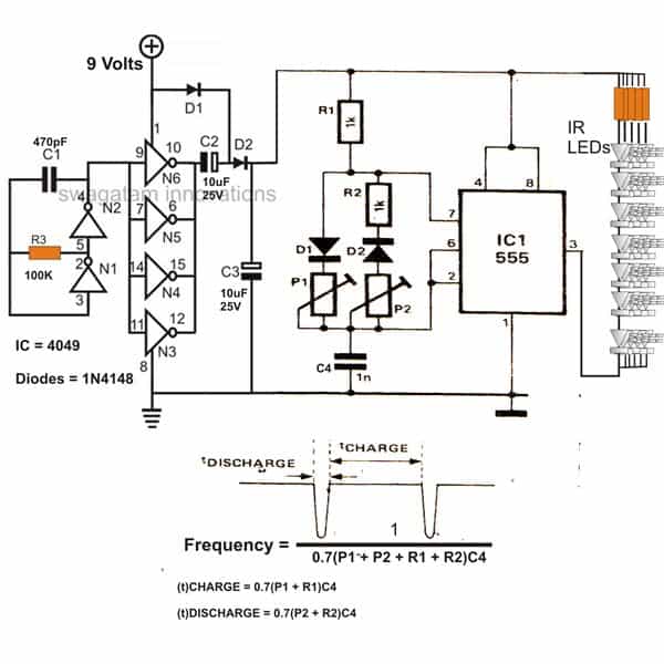
The adjoining design shows a simple IR flood light circuit diagram for IR illumination applications.The 4049 section is the basic voltage doubler circuit which effectively boosts the 9 V supply to a level of around 15 V which further becomes the supply voltage for the next 555 pulse modulator section.
The voltage is suitably pulsed as per the settings of P1 and P2 for driving the associated IR LEDs.
The main feature of this infrared IR LED flood light circuit is that it utilizes just a single PP3 9 volt battery and yet is able to provide lights (IR) at dazzling levels.
Infra Red (IR) LED Flood Light Circuit Diagram
Parts List
- Resistors are 1/4 watt 5% CFR
- 100 k = 1
- 50 Ω = one on each LED string
- 1 kΩ = 2
- P1, P2 preset trimpots 10 kΩ = 2
- Capacitors
- Ceramic 470 pF = 1
- Ceramic 1 nF = 1
- Electrolytic 10 µF / 25 V = 2
- Semiconductors
- Diodes 1N4148 = 4
- IC 555 = 1
- IC 4049 = 1
- Infrared LEDs = as per the requirement on the LED strings
How to Calculate the Components
Oscillation Frequency of the 555 Timer (Astable Mode):
The 555 timer operates in astable mode, generating a pulsed output for driving the IR LEDs. The frequency of oscillation is given by:
f = 1 / [0.7 * (P1 + P2 + R1 + R2) * C4]- P1 and P2: Potentiometers (used for adjusting charge and discharge times)
- R1 and R2: Fixed resistors
- C4: Timing capacitor
Charge Time (tcharge):
The charge time is determined by the resistors P1 + R1 and the capacitor C4:
tcharge = 0.7 * (P1 + R1) * C4Discharge Time (tdischarge):
The discharge time is determined by P2 + R2 and C4:
tdischarge = 0.7 * (P2 + R2) * C4Total Period (T):
The total period of the oscillation is the sum of the charge and discharge times:
T = tcharge + tdischarge
T = 0.7 * [(P1 + R1) + (P2 + R2)] * C4
Frequency (f):
The frequency of oscillation is the reciprocal of the total period:
f = 1 / T
f = 1 / [0.7 * (P1 + P2 + R1 + R2) * C4]
Example Calculation:
Lets Assume the following component values:
P1 = 10 kΩ
P2 = 10 kΩ
R1 = 1 kΩ
R2 = 1 kΩ
C4 = 1 µF
Step 1: Total Resistance in the Timing Network:
P1 + P2 + R1 + R2 = 10 k + 10 k + 1 k + 1 k = 22 kΩStep 2: Calculate the Frequency:
f = 1 / [0.7 * 22 * 103 * 1 * 10-6]
= 1 / [0.7 * 22 * 10-3]
≈ 1 / 0.0154 ≈ 65 Hz
f ≈ 65 Hz
IR LED Driver Section:
The IR LEDs are driven by the output of the 555 timer which pulses them at the calculated frequency. The current through the LEDs depends on the supply voltage (9V) and the series resistors. The diodes (D1 D2) and capacitor (C3) help stabilize the supply voltage and reduce noise.
Resistor Selection for LED Current Limiting:
Use Ohms Law:

RLED = (Vsupply - VLED) / ILED

Let us assume Vsupply = 9 V, VLED = 1.5 V (for IR LEDs), and desired ILED = 20 mA.

RLED = (9 - 1.5) / 0.02

RLED = 7.5 / 0.02

RLED = 375 Ω
We can Use a standard resistor value of 390 Ω.



Questions & Answers
Good day Mr Swagatam.
I need help with a Ir circuit, similar to the above circuit. I will not be needing the ic 4049 in my circuit. I will build or buy my own power supply for this circuit.
I have 15 x 5 Watt Ir led’s in series or parallel, that i want to drive with a 555 ic like your above circuit. I would also like to have a day / night switch incorporated in the circuit. If i connect all 15 led’s in series at 1,6 volt each, that will equal to 24 volt. the 555 ic can not handle 24 volt, so the 555 circuit will be using +/- 9 to max 15 volt, driving a transistor or mosfet that, in turn, drives the 15 led’s from a 24 volt power supply with enough amps for the led’s. If i connect the led’s in parallel, i will need 1.6. volt at much higher amps.
Which will be the best way to connect these led’s, series or parallel, for a pulse modulator circuit like your above circuit.
Would you please be so kind to help me with a circuit diagram to drive my led’s. I want to use these led’s to aid my surveillance cameras at night, the criminals brake into my workshop and steel my tools.
See the specs of my led’s
LED-UV-STAR-98E
14M6540
170492-191009A.pdf
CP-P5WAR85 / 170492
EIE
INFRARED LED 5W 850nM 1.4A 1.8V
IR, 1.6-2.0V, 1400mA , 500-600mW
Hi Ian, you can divide the LEDs into two strings, one having 7 LEDs, other one having 8 LEDs, and use separate resistors for each of the strings, and put both the strings in parallel. This will allow you to use a single common 15V supply for the whole unit.
Use 0.7 ohms for the 8 LED string, and 1.2 ohms for the 7 LED string. Both the resistor must be 10 watt rated
Will the components in this circuit be capable of handling 2.8 amps? Two parallel strings, one 7 and one of 8 at 1.4 amps each.
How and where do i implement the LDR into this circuit for a day/night switch?
Please Mr Swagatam i need a circuit diagram. I can not design my own circuits, i can only only build from an existing circuit.
Thank you.
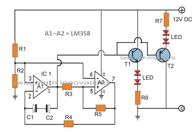
OK here’s the circuit diagram with the required details:
For the LEDs, use two parallel strings having 7 LED and 8 LED, with a calculated resistor in series with the each LED string as explained previously
Hi,
I have a failed IR floodlight which used a relay to pulse power to the LEDs arranged in 22 "strings" of 7 IR LEDs, and was fed from a nominal 12 volt DC 1 Amp PSU. The LEDs are all OK, it is the "relay pulsing" circuit that has failed.
Do you think that this circuit would be a suitable replacement for the "pulsing relay" driver if fed by 12 volts DC?
Regards,
Carl in the UK.
..the 4049 stage can be ignored and eliminated.
Hi, you can modify and use the above explained design for pulsing the LEDs, relay may not be required as it can be done through a transistor stage also by configuring it with pin#3 of the IC.
HI Engr. Swagatam….
I have a few questions…
In what mode does the IC555 operate…
and hey can you help me out about the circuit's theory of operation?
cause I need this in our school….our goal is to find any circuits with digital IC….excluding IC555…and found this circuit ok…so I guess I need your help…
btw the 555 here is ok…just need to know the mode…
tnx alot ^_^
Hi eshkariel, the mode is astable with variable PWM functionality using the shown oppositely configured diodes at its pin#7 and the pots.
the explanation can be very lengthy, so it may not be possible here….
Good afternoon Sir,
what are the specification of the ir led? 5mm, 3mm or 1 watt?
Good morning eshkariel,
it's 5mm, 20mA
hi swagatam…..
what is p1 and p2 in the circuit?
hi hashir,
p1, p2 are variable resistances called pot or preset.
Good evening swags…
what is the use of p1 and p2
can I make 14 strings of led? and what is the value of r4 in case of 14 led?
can I use it used for night vision?
eshkariel, yes you can connect 3 leds in series and more such series in parallel, in that case you wont need te 4049 voltage doubler stage, you can power the circuit directly with the 9V batt.
you can use 470 ohms for each series.
pi, and p2 are for adjusting the intensity of the Leds and can be adjusted as per individual preference
good afternoon Sir!
Can I make 3 led's in series and what resistor will I use. Then can I make them 3 led's in parallel (consisting of 3 led's in series with resistor). 9 led's all in all.
Can you give me specific P1 P2 R1 R2 and C4? I dont know how to calculate the frequency or I dont know the purpose of those so just give me a constant values for a good night vision flashlight..
thanks
-eshkariel
Good evening Achilles
p1 and p2 are for adjusting the intensity of the LEDs
14 leds can be used.
yes, it's for night vision application.
lol i really dont thing they eat lol. . . . .
…let's hope so lol…
hi ya swagatam
Do you have a parts list for this setup. . . ..I am building basic 9v Lights with 18 – 20 10mm IR Leds
940nm, 1.2v FV 20ma and 30 deg beam
Gotta love foolin around with gadgets lol
Hi John,
The presets can be around 10k, the remaining values are printed on the diagram, just click on the diagram to get an enlarged view and the details…
yep, foolin around is like enjoying….so keep it up,
and if you get hold of any of those creepy things do let us know how they look and what they eat…hehe..just jokin buddy
Goodday Jacques,
The circuit hasn't been built yet by me, you can use the formula given in the diagram for evaluating P1, P2.
Hi Simon,
The frequency is determined by C4, making it lower increases the frequency and vice versa.
Here's the LED specs used above:
5mm LED
940nm wavelength (most common)
20 degree beam width
20 mA continuous, 100 mA pulse
Approx 1.6V forward voltage
The IC 4049 is used as a voltage doubler so that more number of LEDs can be accommodated in series, while the 555 is used as a PWM controller.
Actually the 4049 is not needed, you can simply use the 555 IC solely for the required actions, albeit you will need to remove a few LEDs from each series.