In this article we will study a simple LED tube light circuit which could be directly replaced with faulty 40 watt T17 fluorescent tubes and fitted directly on the existing fixture. Thus the circuit is compatible with all standard iron ballast fixture assemblies.
How Conventional Fixtures are Wired
As shown in the below diagram, traditional fluorescent fixtures consist of two side connectors, a series iron core ballast and a complementing series starter unit.
All these are normally wired as shown below over a long MS metal fixture. The florescent tube gets fixed between the two spring loaded side connectors which have a couple of embedded clips for holding and connecting the tube light end pinouts.
A Standard Iron-core Ballast Fixture Wiring
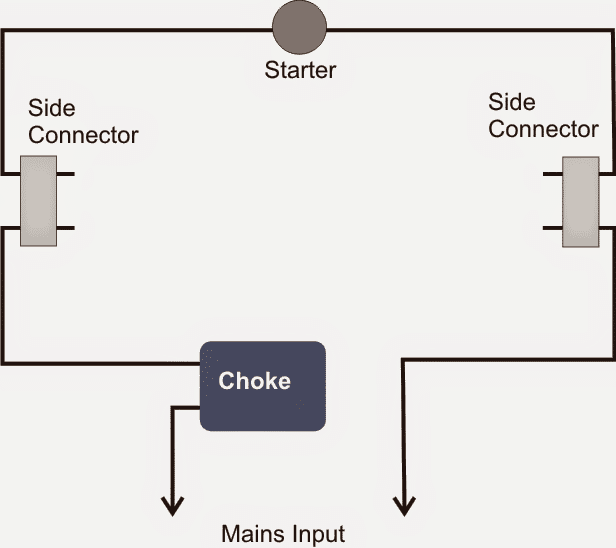
The starter is wired across one of the adjacent pair of end pins while the ballast is attached in series with the other adjacent pins of the side connectors.
The series outputs from the ballast and one of the connectors are finally terminated for receiving the mains AC voltage.
When AC is first switched ON, the starter fires randomly and switches the tube in a flickering mode, which forces reverse high voltage EMFs to be generated by the ballast.
This kick starts and ignites the tube internal gas and illuminates the tube bypassing the starter such that now the starter no longer conducts current, rather the current is now conducted through the illuminated tube internal gaseous path.
Once the tube is triggered fully the choke or the ballast simply acts like a current limiter for restricting a safe specified amount of amps to the tube as per the resistance of the ballast coil. In good quality ballasts the resistance or the number of turns inside the ballast will be correctly calculated to minimize heat generation and ensure longer tube life.
Drawback of Electrical Fluorescent Type Fixtures
However one big drawback with these traditional iron core ballasts is the emission of excessive heat while limiting current to the tube, which makes it rather inefficient as far power saving is concerned.
LED tube lights similar to T17 fluorescent have become very common in the market nowadays but these come with their own specific fixtures, and cannot be replaced on the traditional FTL fixtures.
Since most homes have these traditional iron core type fixtures fitted on their walls, getting an LED tube replacement which is directly compatible with these becomes highly desirable and handy.
In this post I have explained a simple LEd tube light circuit which provides all the good features of LED technology and yet is directly replaceable over conventional T17 FTL fixtures.
LED Tube directly Replaceable with Fluorescent Tube Fixture
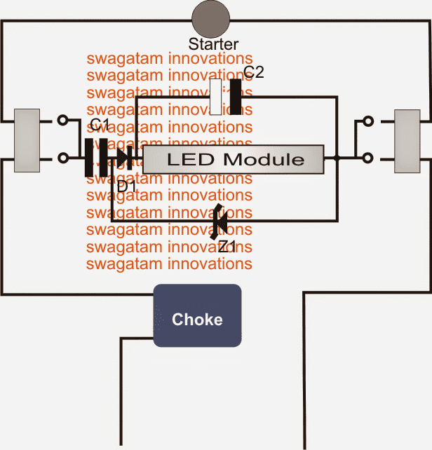
The circuit design could be seen in the following diagram located at the middle of fixture wiring and shows how the circuit configuration allows a direct installation feature.
The circuit is an ordinary capacitive power supply which is half wave rectified by D1 and filtered by C1.
The zener Z1 ensures a constant 180V DC across the connected LED module.
The LED module is nothing, but consists of around 50 numbers of 1 watt LEDs in series end to end.
The existing choke or the iron ballast is allowed to be in the wiring chain which now acts like a perfect surge suppressor and helps arresting the incoming current in-rush during initial switch ON.
The starter however plays no role in the design and may be either removed or its presence may be ignored.
LED Tube using the Old Electrical Fixture
Parts List
C1 = 105/400V
C2 = 10uF/400V
D1 = 1N4007
Z1 = 180V zener, 1 watt
LED Module = see text

Questions & Answers
Thank you Sir.
Sir, I want to assemble the project. I want to know whether the light emitting of this led tube will be as good as the original Tube. How the power of zener diode ” one watt is” calculated?
VG, the light will depend on the number of LEDs and the C1 value, to make it even better than a 40 watt tube, you can use 50 to 60nos of 1 watt LEDs in series, and for the zener diode you can use a 200 V 2 watt zener diode.
for the capacitor you will have to put 6 nos of 1uF/400V capacitor in parallel.
for C2 you can use a 10uF/400V capacitor.
the above set up will give you around 50 to 60 watts of clean bright LED light
True, 11nos of 30ma led equals to 1 watt I.e 0.030 X 11= 330ma and 330ma X 3v = 1 watt aprox. I am using 19 of it on a cfl base (with captive power supply along with a LM317 to clamp the current) for the last 2 years aprox which easily replaces a 9 watt cfl and takes only 1.71 watts (19 X 3 = 57 volts, 57 v X 0.03 ma = 1.71 watts.) now will 2X 1watt led give same illumination?? Thanks
19 in series needs 19 x 3.3 = 62V, while 2nos 1 watt LEDs will need 3.3 x 2 = 6.6V….huge difference…so 1 watt LED will work very inefficiently than your 19 LED lamp….
regarding led module this may be a silly question.
We are here to use LED based lights so that our power consumption comes down. now as leds from 1 watt module and above, produces heat and need to be mounted on a heat sink. So there is a power loss which is wasting as heat. Is it acceptable to use 8mm or 10mm leds in larger nos. so thatminimum heat is generated?? thanks
the light ratio of 1 watt leds is extremely high compared to the heat it generates, if ordinary leds are used a huge number of these would be required in order to produce illumination on par with 1 watt leds.
Hi Swagatam,
Most of the old tubelights are replaced with electronic chokes now a days, can we use the same in that fitting too…. if not please request you to make the necessary modification to support them.
Regards
Gopal
Hi Gopal, if the choke is in series as shown in the above diagrams then it would work for electronic chokes as well, however the electronic ballast wouldn't be involved with the LED tube light illumination in anyway, only its internal NTC, bridge etc would come into play.