LI-FI is buzzing around the Internet since past few years; recently LI-FI is gained more popularity around the internet and developers. LI-FI stands for Light Fidelity which was coined by Harald Hass.
Circuit Objective
The objective of LI-FI is transfer data through visible light. Since the bandwidth of visible light is 10,000 times more than Radio waves, more data can be transferred through light at short period of time.
Visible light communication (VLC) eliminates the risk of some disease caused by the Radio waves due to long period exposure.
This protocol can be adapted where Radio waves are restricted, such as airplanes, hospitals, and in some research facilities. Researchers reached bit rate of 224 GB/s which is 100s of times faster than our average WI-FI connection at home or office.
This article explains about the basic idea how to make a very simple LI-FI circuit in which we will be able to transfer any audio source through light and receive it from the receiver which is placed few feet from the Transmitter.
Here explained about analogue communication through light, where as original LI-FI system uses digital communication, which is more complex and difficult to make one at hobby lab. But the concept is exactly the same.
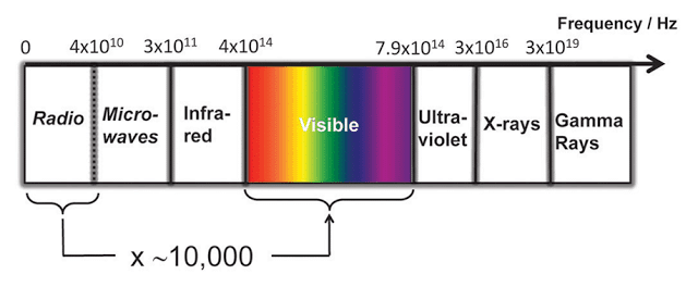
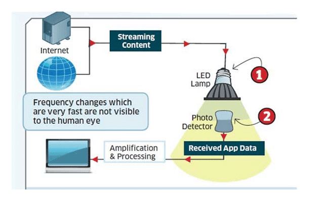
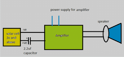
Here is a simple block diagram explaining LI-FI:
The Design:
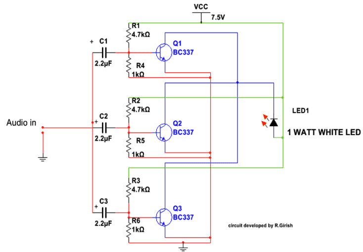
The circuit consists of two parts, which are receiver and transmitter. The transmitter consists of 3 transistors and few passive components paired with 1 watt LED. The transistors are configured as common emitter amplifiers which alters the LED brightness with respect to audio signal.
But changes in brightness due to audio signal will not visible to human eye. We only see static illumination of white LED. The receiver consists of a photo detector (here I used solar cell) which is paired with an amplifier. The sound output is given by the speaker.
The transmitter is transistorized amplifier which consists of 3 amplifiers connected in parallel to drive the 1 watt white LED.
Each transistor base consists of voltage divider which gives necessary bias for the individual transistor. The input stage has capacitors at each transistor’s base for blocking DC signals which could degrade the quality of output.
LI-Fi Circuit Diagram
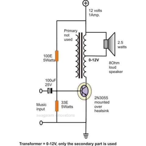
Update: The above design can be also tried using a single transistor as shown below:
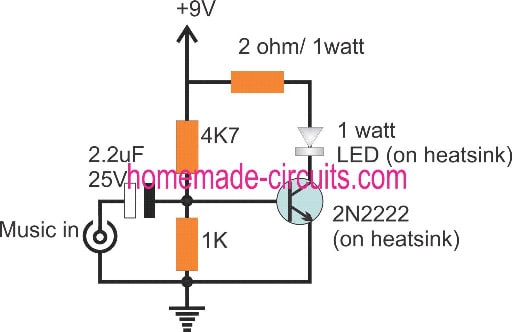
You can use a current limiting resistor series with LED if you want operate the circuit at higher voltage (say 12V).You can also use standard 0.5mm white LED with current limiting resistor. For an audio source you can use mp3 player, mobile phone or a microphone with pre-amplifier etc.
The receiver consists of a 6 volt solar cell (3 volts above works fine) in series with 2.2uf capacitor which is paired with an amplifier. The amplifier need not to be the same illustrated here, but you can use any amplifier lying around your house. But make sure it as good sensitivity.
Amplifier Schematic
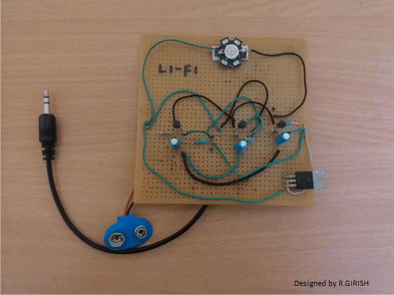
Here is author’s prototype
Li-Fi Video Clip:
You can use any amplifier with good sensitivity for receiver part. To test this circuit, go to a room where ambient light is dim and make sure no nearby electrical light source.
Place the 1 Watt LED parallel to solar cell. Turn ON the power supply for both transmitter and receiver, give audio input to transmitter, adjust the volume to transmitter. You can here clear audio sound on the receiving speaker.
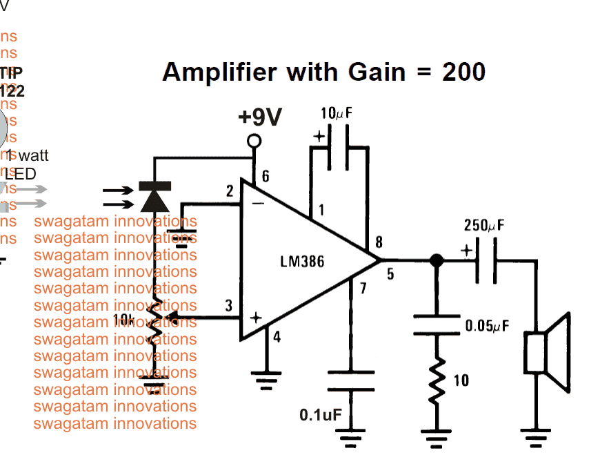
The above explained Li-Fi circuit can also be tried using a photodiode as shown below, where the amplifier section is replaced with a LM386 amplifier circuit:
UPDATE:
Some Important Notes and Considerations Regarding the above Li-Fi Circuit
In this Li-Fi the LED does flicker, but it is in-significant for our eyes to detect.
If your eyes can detect those flickers, something wrong with the build.
The change in the brightness of LED due to the audio input is very small, but there is change in the brightness, where our eyes can’t detect.
If there is no audio input, the LED stays solid ON, the solar cell produce some voltage. The input capacitor at receiver blocks those DC signal giving almost zero voltage to amplifier.
When we apply audio signal at transmitter there will be change in the LED’s brightness (Very small). The solar cell replicates the small varying voltage, the capacitor will allow the small variation in voltage amplitude to amplifier and rejecting strong constant DC voltage.
The amplifier must have good sensitivity since the input is feeble. Probably that’s why many readers are commenting on loudness of the audio.
I have used old-school home theater’s amplifier which had very good sensitivity and the resulting output was LOUD and CLEAR.



Questions & Answers
Sir ,
U sure this circuit works? Don't we need any microcontrollers for doing lifi??
The concept is dead easy and you won't need anything complex for a basic design as above, however in the above design the light would fluctuate with music so it must be superimposed on a carrier frequency and then transmitted. the receiver side would also need a circuit capable of extracting the superimposed music from the carrier signal for the expected LiFi output
isn't possible to make lifi from my wireless home broadband? if its yes can you send me a video? thanks
sir,Which capacitor used in solar celll 2.2uf or 100uf ?? In block diagram 2.2uf is used & reciver circuit 100uf used. Which is the correct one?
Nikita, the value is not critical, you can use any electrolytic capacitor at the shown input position of the amp.
What is the 3v & abovel solar cell value of power & current.
it's the specification of the solar cell…it's also not so critical.
What is the circuits for receiver and transmittier
Just for confirmation …thanx
Am so happy SWATAGAM just because i managed to receive sound to my receiver end . thanks very much AM CALLED KAKUMBA DAVIS
that's great Davis, I am glad you could succeed with the above explained circuit.
May I know the specifications of the amplifier?
Will any audio amplifier do?
Is it necessary to modulate the input?
I am in first year of engineering and doing this circuit as my project, so would you please guide or suggest any modifications to the circuit?
any audio amplifier can be used for the conversion.
modulation will result in a better and a stable Light output from the LED but the circuit design could be a bit complex.
What's that 100e 5watt, its solar panel.
And can I use 12v2amp for receiver
that's a resistor, you can try some other amplifier circuit if you find this one difficult or crude in its layout
12V 2 amp will do
We have made the transmitter and receiver as mentioned.
We found that the data is getting transmitted through led but we aren't able to receive that using solar panel ie. The voltage drop across solar cell remains almost constant
Now what shall we do to increase sensitivity of the panel?
it should be a solar cell not a solar panel, try with a solar cell which are normally used pocket calculators.
and first make sure your amplifier is working OK, test it separately by feeding a music input from a cell phone's headphone socket
Can i use photo diode or ldr instead of solar cell
yes you can after suitable modifications
What shoud i change if u use photo diode
Plz help me out im trying this since 5 days
I'll try to update a new diagram tomorrow using a photo diode.
Why are we getting a pulse waveform across led?
Why does it change if we swap collector with emitter?
In the common emitter mode you will get square wave pulsed waveform, while in the common collector mode or emitter follower mode you will get an exact replica of the fed music… reinforced with higher current
We got the audio output
Thanks a lot for solving our doubts 🙂
I am glad it worked for you…congrats!
Hello,
What kind of LED and photodiode do you use ?
any standard photodiode will work.
Sir, if I am giving a signal from a signal generator to the input should I do any changes in the transmitter . If yes can you plz tell me those changes. Thank you
Amarnath, no changes would be required for the signal generator signal, it's also a kind of frequency so will work just as a music input is supposed to work
Thank you sir, I was able to give the input via a signal generator but it seems I'm only able to transmit and reciece square waves.. Other waves(above 0.016V) are saturating the output.. If I decrease the gain of the OP amp will it work ?
Thanks again
Hi Amarnath, the gain of the shown LM386 amp circuit is already set at the max 200 range.
you can probably try to optimize the volume control for getting improved results, and reduce distortions.
Can you show ptototype transmiter and receiver in detail, please your help thanks
it has the modulation circuitry responsible
please respond
No, the above circuit is not modulated with a carrier wave.
there is no modulation ?????? and how you chose the value of resistors and capacitor and if possible send me the Shema block and the role of each block answers please it's urgent
How am I supposed to connect this with the internet? :/
connected a stereo jack (3.5mm) to the radio. I connected the ground pin of the jack to the cathode of a small LED. The left channel pin was connected to the anode of the LED. In addition, I connected a 9V battery with a 1k ohm resistor to the anode and cathode of the same LED. This was my transmitter circuit.
In the receiver circuit, I simply connected a solar panel (6V) to the speaker. I powered the speaker through wall socket (230 V AC current). It worked. I was able to transmit audio.
Now, I want to be able to transmit a video, in the same way you did in your TED talk a few years ago. This time, my input is an AV jack from an old DVD player. I connected the ground wire of the AV cable from the DVD player to the cathode of LED and the positive wire to the anode of the LED. In addition, I connected a 9V battery with resistor to the LED. As above, I connected the solar panel (6V) directly to the AV cable of a mini screen which takes AV input. The screen is powered by a wall socket.
This time however, nothing shows up on the screen. I tried using an LED of higher brightness (1 watt). Now, only an icon shows up on the screen which says "AV 1 detected" for a short while and then disappears altogether.
I would be obliged if anyone explained to me how you achieved video transmission through Light Fidelity.
appreciate your efforts, however a video signal cannot be transmitted through a LED so easily, because a video signal may have many complex frequency data embedded together which cannot be transmitted or received without special encoders and decoder circuits. Music is a single frequency data therefore it may be much easier to send music through a Li-Fi circuit, but not a video signal
Hi spyros,
I found the resistor values by trail and error method. I used different values of resistor and I found the above specified values optimal. Initially I chose BC548, but too weak to handle 1watt LED, so gone with stronger transistor BC337 these info can be found in the datasheet.
regards
Hello sir, I have designed exactly the same circuit as yours, but i am using function generator instead of Audio in. But i am getting more than 8 volts output. Can you please help me with that. Which components should i change or is this circuit only for supplying audio signals? I need to ask one more thing that we are supplying positive VCC directly to LED terminal, is it fine?
Hello Abdullhaq, the circuit can be use for transmitting all kinds of frequencies, so it should work with your function generator output also, first make sure that your function generator output has only pulsating DC and no constant DC…and the solar cell gets no other ambient light except the function generator frequency light
Thanks sir, But how should i limit the output voltage to around 3.2Volts that can be handled by LED. Because i am getting more than 8 volts output even without attaching function generator.
I am assuming you have connected the LED with the function generator output, in that case you can connect a resistor in series with the LED to limit current and optimize the volts automatically, however if this 8V is constantly available then that's incorrect and your function generator could be faulty according to me.
alternatively you can connect a 10u/25V capacitor in series with the LED resistor…and a another 10K from LED/capacitor junction to ground.
…sorry I think I got you wrong, I guess you are referring to the first circuit in the above article, yes the LED will be lit while no signal is connected to the circuit, but as soon as you connect the function generator, the negative signals from it will begin shutting off the LED at the specified frequency rate and you will start seeing the required conversion from the LED.
Thank you so much sir. It worked fine for me, but the volume is really low. Ill try and change the speakers.
for the transmitter part can we use 9v Vcc instead of 7.5v?
I am glad it worked for you Ananth, yes 9V can be also used instead of 7.5V.
you can try a better amplifier design for improving the sound quality
which type of amplifier can we use for our receiving circuit,can we make one of that and if yes then how??
Is it necessary to use a solar cell can i use a LDR instead. What would be the difference. Expecting the answer soon. Thank you!
LDR can be used in the last circuit instead of the photo diode…
you can salvage it from an old calculator device…