White LEDs have become so common nowadays that even school kids today know how to use them for making simple LED projects. LEDs are typically used for illuminating purposes, the discussed circuit is also intended for similar applications. The post talks about how to wire LEDs and battery to make a simple DIY LED flashlight.
White LEDs are Awesome
Before the advent of the efficient white LEDs, incandescent bulbs were the only option which could be used for making flashlights.
Though not as bright as a white LEDs, filament bulb type flashlights served the purpose quite well, until LEDs were invented, which completely transformed the scenario.
White LEDs are so efficient that they produce 4 times more light than a conventional incandescent type flashlight yet consume 60% less power.
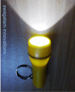
No surprise why white LEDs are being considered as the future option for all lighting applications.
The LED flashlight circuit explained here is very simple, and it simply requires to follow the instructions as given for making it successfully.
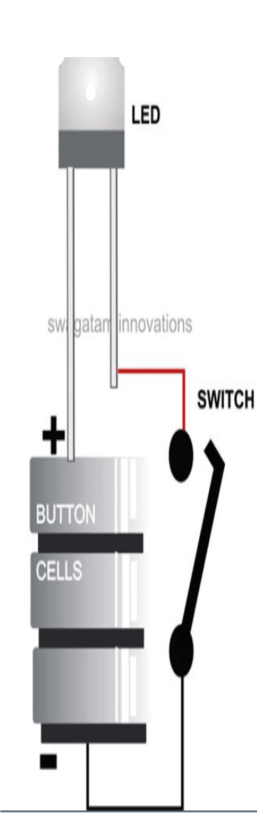
The proposed circuit utilizes just a single high bright white LED, three 1.5 volt button cells and a switch.
White LED Forward Drop Voltage
As we all know, a white LED typically needs a 3.5 volt supply for illuminating directly, without the need of any current limiting resistors.
Therefore here we connect the three 1.5 volt button cell connections directly across the LED terminal for switching it ON and for getting the intended illumination from it.
Being low in current the 4.5 V output from the cells does not produce any damaging effect, rather automatically adjusts to illuminate the LED very brightly.
Now add a switch anywhere in between the above cell and LED connection, it becomes switchable manually, your simple LED flashlight circuit is ready.
The discussed flashlight arrangement will require a proper casing for holding all the parts in place securely so that it can be comfortably operated by hand.
A sample design is shown below, which may be copied for making the enclosure for the above circuit.
Circuit Diagram
Economical Flashlight using Switched Output
Due to the fact the full illumination of a flashlight is not always required, an appropriate dimmer might be a pleasant power saver.
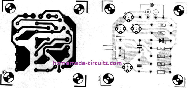
The device was created around an astable multivibrator whose duty-cycle could be adjusted through potentiometer P1. The diode is included to enhance the rise time. The diode can be a 1N4148.
Through T3 the AMV switches transistor T4, which in turn switches the LED lamp. T4 can work without any heatsink.
The control range is such that the lamp could be tweaked to consume at about one third of its total brightness level; which means the batteries will likely then continue to operate 3 times more than its normal life.
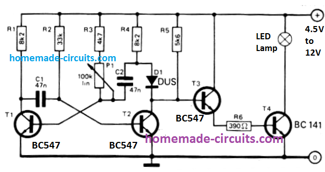
The implementation of the circuit is naturally not restricted to flashlights alone; it could likewise be employed for solar lights, radio dial brightness, etc.
If an LDR is used in place of P1, it might be possible to achieve an automated dimmer that self adjusts the illumination of the lamp depending on the background light conditions.
Flashlight with Charger Circuit
The following, very useful concept of a chargeable flashlight circuit was contributed by a dedicated follower and reader of this site, "Ersa".
The first image below shows the circuit diagram and the parts list of the chargeable flashlight.
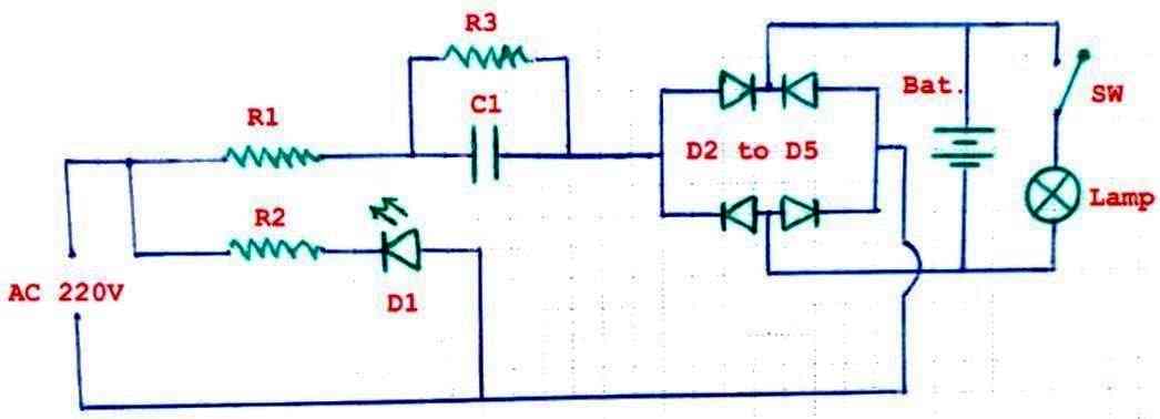
- List of components:
- R1 = 1R5 1/4W
- R2 = 220k 1/4W
- R3 = 270k 1/4w
- C1 = 470nf 400v
- D1 = LED red
- D2 to D5 = 1N4007
- Bat. = 2.4V 700mAh = 2×1.2V NiCd or Lead Acid
- Lamp = 2.5v 300mA
The following images show the specification of the high value capacitor which forms the crucial part in the circuit for charging the battery.
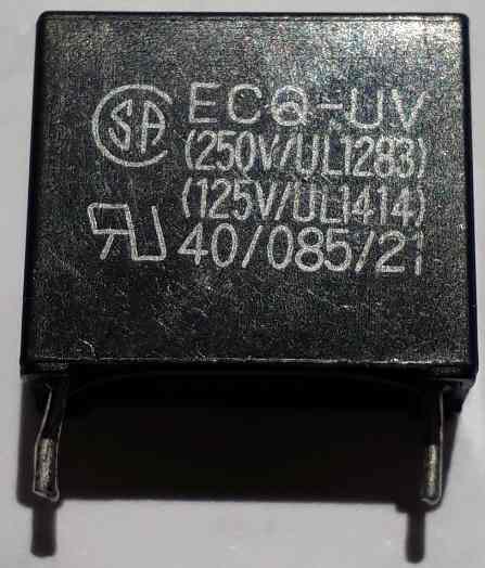
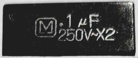
Warning: The circuit is not isolated from mains AC, and therefore is greatly prone to lethal electric shock if touched in an uncovered and switched ON condition. Appropriate precaution is strictly recommended for the user.




Questions & Answers
Best info about flashlight apps used in android phones. Thanks for sharing
Enjoyed article on led flashlight, but having problems with my Nebo led/USB rechargeable light which has dimming feature. Have contacted company on several occasions of light not working or not accepting charge with same reoccurring problem and every time company has replaced light to a total of four times . Trying to understand circuitry and possibly trouble shoot. Realize a little off topic but would appreciate suggestions, thx Tom
Glad you enjoyed the post, and I understand your problem, however the circuit configuration can be a lot different for different brands, so without seeing the internal wiring and the board it can quite difficult to troubleshoot the unit, or suggest you the tips regarding the troubleshooting
Dear Sir Swagatam
Hello. I hope this letter fins you well.
would you please inform me if the circuit contributed by Mr. Ersa is suitable to charge 2 nos of 1.2 volt Ni-Mh batteries connected in series?
Thank you in advance for your kind response
with warmest regards
Scinerely
Ali
Thank you Ali,
The diagram by Ersa is almost good, but there’s one serious issue in the circuit, the voltage is not regulated.
So to regulate the voltage we must add around 6 diodes in series across the battery. Cathodes will be towards the negative of the battery and the anodes towards the positive of the battery.
However, remember, since the circuit is not isolated from mains AC it is extremely dangerous to touch it while it is plugged in to the mains…
Dear Sir Swagatam
Hello,
Thank you so very much for your prompt and kind response. I would greatly appreciate it if you would kindly explain the role of the six diodes you instructed to place across the two batteries under charging.
A friend of mine sent me a diagram of a charger related to this topic this afternoon. I will forward it to your email address hoping that you can provide me with your valuable
instructions. Perhaps it could also be beneficial for other visitors to your interesting site.
Warmest regards
Truly yours
Ali
Thank you Dear Ali,
The diodes will make the charging voltage across the battery constant.
Since each diode drops around 0.6V, so 0.6 * 6 = 3.6V which is good enough for charging a 3V Ni-Cd battery.
You can send the diagram to my email ID, I will check it out…
Hello dear Sir engineer Swagatam
I appreciate your very useful explanation regarding the set-up of diodes. Thank you very much.
Another thing to mention is that, shortly after I inquired about the 6 diodes last night, I sent the diagram to your email address.
Warmest regards
Sincerely yours, Ali
Thank you Dear Ali,
Here’s the diagram you sent me. But it seems the diagram is charging the Ni-Mh battery from a 5V source. Also I could not understand the role of the NPN transistor, and the diode D1 which shows inward arrows, meaning it could be a photodiode:
https://www.homemade-circuits.com/wp-content/uploads/2025/04/NiMh-charger-circuit-diagram.jpg
Dear Sir Swagatam
Hello, hope you are fine
I forwarded your kind response, to my friend and he sent the following response to me along with the edited diagram of the circuit which I just sent to your email address:
1. I have mistakenly inserted the symbol for LED diode with inward arrows on the diagram. The arrows of the LED are outward.
2. R1 and R2 act as voltage dividers and provide current bias for Q1 to function. When the LED lights up, we have a steady voltage of around 1.9 volts on the LED, and Q2 receives a constant current of around 250 mA from AA Ni-MH batteries.
His response is not sufficient for me, and I do not completely understand what the circuit actually does. Since I do not have any other alternative, I am convinced that I should choose Ersa’s diagram along with your instruction to add 6 rectifier diodes, as the charger for my Ni-MH batteries.
Thank you very much for being so patient (which I appreciate it a lot) and kind to your fans.
Warmest regards,
Sincerely yours,
Ali
Thank you so much Dear Ali, for the clarification,
Yes the PNP is configured as a constant current generator, I missed it completely.
But in our case we need a circuit with 220V AC input so the capacitive circuit by Ersa looks good since the current from the the 474 capacitor is just 25mA which is very low for any Ni-MH battery, so not an issue, moreover the diodes across the battery will make the voltage constant and below the full charge level of the battery.
You are most welcome, Ali, I hope Ersa’s circuit works OK for you. However the charging speed will be very slow and might take 24 hours for the Ni-Mh to charge fully…
Dear Sir Swagatam
Hello,
Thank you very much for your kind response. I have my last question regarding replacing the 474 capacitor with a 105. Could I have your instructions for this replacement?
Thank you for all your help and support
Warmest regards,
Truly yours,
Ali
Thank you Dear Ali,
Yes you can replace the 474 with 105, this will increase the current to over 50mA, and the battery will charge faster. The 6 diodes will make sure the voltage is restricted and constant across the battery.
I saw your new updated diagram in my email, it looks good now…