Designing an inverter transformer can be a complex affair. However, using the various formulas and by taking the help of one practical example shown here, the operations involved finally become very easy.
The present article explains through a practical example the process of applying the various formulas for making an inverter transformer.The various formulas required for designing a transformer has been already discussed in one my previous articles.
Update: A detailed explanation can be also studied in this article: How to Make Transformers
Designing an Inverter Transformer
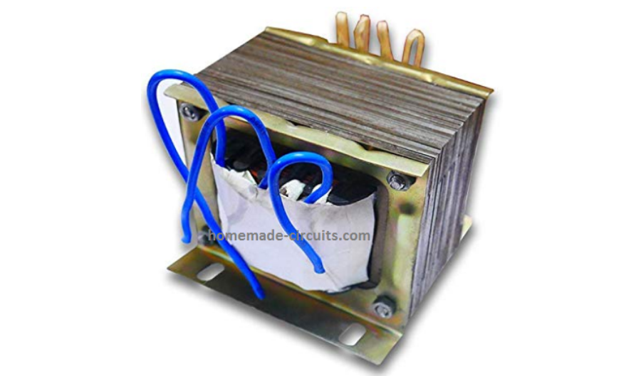
An inverter is your personal power house, which is able to transform any high current DC source into readily usable AC power, quite similar to the power received from your house AC outlets.
Although inverters are extensively available in the market today, but designing your own customized inverter unit can make you overwhelmingly satisfied and moreover it's great fun.
At Bright Hub I have already published many inverter circuit diagram, ranging from simple to sophisticated sine wave and modified sine wave designs.
However folks keep on asking me regarding formulas that can be easily used for designing a inverter transformer.
The popular demand inspired me to publish one such article dealing comprehensively with transformer design calculations. Although the explanation and the content was up to the mark, quite disappointingly many of you just failed to grasp the procedure.
This prompted me to write this article which includes one example thoroughly illustrating how to use and apply the various steps and formulas while designing your own transformer.
Let’s quickly study the following attached example: Suppose you want to design an inverter transformer for a 120 VA inverter using a 12 Volt automobile battery as the input and need 230 Volts as the output. Now, simply dividing 120 by 12 gives 10 Amps, this becomes the required secondary current.
Want to learn how to design basic inverter circuits?
In the following explanation the Primary Side is referred to as the Transformer side which may be connected at the DC Battery side, while the Secondary side signifies the Output AC 220V side.
The data in hand are:
- Secondary Voltage = 230 Volts,
- Primary Current (Output Current) = 10 Amps.
- Primary Voltage (Output Voltage) = 12-0-12 volts, that is equal to 24 volts.
- Output Frequency = 50 Hz
Calculating Inverter Transformer Voltage, Current, Number of Turns
Step#1: First we need to find the core area CA = 1.152 ×√(24 × 10) = 18 sq.cm where 1.152 is a constant.
We select CRGO as the core material.
Step#2: Calculating Turns per Volt TPV = 1 / (4.44 × 10–4 ×18 × 1.3 × 50) = 1.96, except 18 and 50 all are constants.
Step#3: Calculating Secondary Current = 24 × 10 / 230 × 0.9 (assumed efficiency) = 1.15 Amps,
By matching the above current in Table A we get the approximate Secondary copper wire thickness = 21 SWG.
Therefore the Number of Turns for the Secondary winding is calculated as = 1.96 × 230 = 450
Step#4: Next, Secondary Winding Area becomes = 450 / 137 (from Table A) = 3.27 sq.cm.
Now, the required Primary current is 10 Amps, therefore from Table A we match an equivalent thickness of copper wire = 12 SWG.
Step#5: Calculating Primary Number of Turns = 1.04 (1.96 × 24) = 49. The value 1.04 is included to ensure that a few extra turns are added to the total, to compensate for the winding losses.
Step#6: Calculating Primary Winding Area = 49 / 12.8 (From Table A) = 3.8 Sq.cm.
Therefore, the Total Winding Area Comes to = (3.27 + 3.8) × 1.3 (insulation area added 30%) = 9 sq.cm.
Step#7: Calculating Gross Area we get = 18 / 0.9 = 20 sq.cm.
Step#8: Next, the Tongue Width becomes = √20 = 4.47 cm.
Consulting Table B yet again through the above value we finalize the core type to be 6 (E/I) approximately.
Step#9: Finally the Stack is calculated as = 20 / 4.47 = 4.47 cm
Table A
| SWG | AMP | Turns per Sq.cm |
|---|---|---|
| 10 | 16.6 | 8.7 |
| 11 | 13.638 | 10.4 |
| 12 | 10.961 | 12.8 |
| 13 | 8.579 | 16.1 |
| 14 | 6.487 | 21.5 |
| 15 | 5.254 | 26.8 |
| 16 | 4.151 | 35.2 |
| 17 | 3.178 | 45.4 |
| 18 | 2.335 | 60.8 |
| 19 | 1.622 | 87.4 |
| 20 | 1.313 | 106 |
| 21 | 1.0377 | 137 |
| 22 | 0.7945 | 176 |
| 23 | 0.5838 | 42 |
| 24 | 0.4906 | 286 |
| 25 | 0.4054 | 341 |
| 26 | 0.3284 | 415 |
| 27 | 0.2726 | 504 |
| 28 | 0.2219 | 609 |
| 29 | 0.1874 | 711 |
| 30 | 0.1558 | 881 |
| 31 | 0.1364 | 997 |
| 32 | 0.1182 | 1137 |
| 33 | 0.1013 | 1308 |
| 34 | 0.0858 | 1608 |
| 35 | 0.0715 | 1902 |
| 36 | 0.0586 | 2286 |
| 37 | 0.0469 | 2800 |
| 38 | 0.0365 | 3507 |
| 39 | 0.0274 | 4838 |
| 40 | 0.0233 | 5595 |
| 41 | 0.0197 | 6543 |
| 42 | 0.0162 | 7755 |
| 43 | 0.0131 | 9337 |
| 44 | 0.0104 | 11457 |
| 45 | 0.0079 | 14392 |
| 46 | 0.0059 | 20223 |
| 47 | 0.0041 | 27546 |
| 48 | 0.0026 | 39706 |
| 49 | 0.0015 | 62134 |
| 50 | 0.0010 | 81242 |
Table B
| Type | Tongue Width (cm) | Winding Area (cm²) |
|---|---|---|
| 17 (E/I) | 1.270 | 1.213 |
| 12A (E/12I) | 1.588 | 1.897 |
| 74 (E/I) | 1.748 | 2.284 |
| 23 (E/I) | 1.905 | 2.723 |
| 30 (E/I) | 2.000 | 3.000 |
| 21 (E/I) | 1.588 | 3.329 |
| 31 (E/I) | 2.223 | 3.703 |
| 10 (E/I) | 1.588 | 4.439 |
| 15 (E/I) | 2.540 | 4.839 |
| 33 (E/I) | 2.800 | 5.880 |
| 1 (E/I) | 2.461 | 6.555 |
| 14 (E/I) | 2.540 | 6.555 |
| 11 (E/I) | 1.905 | 7.259 |
| 34 (U/T) | 1.588 | 7.259 |
| 3 (E/I) | 3.175 | 7.562 |
| 9 (U/T) | 2.223 | 7.865 |
| 9A (U/T) | 2.223 | 7.865 |
| 11A (E/I) | 1.905 | 9.072 |
| 4A (E/I) | 3.335 | 10.284 |
| 2 (E/I) | 1.905 | 10.891 |
| 16 (E/I) | 3.810 | 10.891 |
| 5 (E/I) | 3.810 | 12.704 |
| 4AX (U/T) | 2.383 | 13.039 |
| 13 (E/I) | 3.175 | 14.117 |
| 75 (U/T) | 2.540 | 15.324 |
| 4 (E/I) | 2.540 | 15.865 |
| 7 (E/I) | 5.080 | 18.969 |
| 6 (E/I) | 3.810 | 19.356 |
| 35A (U/T) | 3.810 | 39.316 |
| 8 (E/I) | 5.080 | 49.803 |



Questions & Answers
please transformer laminations are very scarce to get, I checked online to purchase for 5Kva, their minimum quantity is in 100kg to 1 tonnes. please sir is there any guide?
Seun, in that case you can consider buying a readymade transformer and rewind it as per the calculations, or go for a ferrite based transformer…
Sir, do you mean ferrite based cores are readily available online easily?
Yes, ferrite cores are easily available and iron core readymade transformers are also available…
Thanks sir. If I want to make the secondary voltage 300v output for the iron core, please how will I calculate the turns.
Thanks Seun
For 300V secondary output, you just have replace all the 230V entries given in the above calculations, with 300V.
please I need a 2000Watt transformer with the following v
alues: Primary:18V-18V,12V center tap, Secondary:600V,230V-0V ,12V-0V
Please can I wind the inverter transformer 350vac? Thanks sir
Yes you can do it..
Hello sir, please how can I use 1 single transformer with secondary output with 8 ends to charge a 4 battery sets in series, 48v. I want to use the trafo to charge the batteries individually not as a whole.
Hello Daniel, What are the voltage and current specifications of the 4 batteries and what are voltage and current specifications of the transformer output wires? Please let me know this, i will try to figure it out.
Thanks sir, Engineer Swatagam, I appreciate. The batteries are lead acid 26ah/12v each, 15v, 3A trafo rating.
output rating of the trafo is 15v, 3amps for each of the secondary windings
Ok, thanks, however, unfortunately if the batteries are connected in series then they cannot be charged directly through aa DC supply, rather it will require an automatic changeover circuit which will detect the low charge levels on each of the batteries and connect the supply to those specific batteries in a sequential manner.
Here’s one example circuit for your reference:
https://www.homemade-circuits.com/lipo-battery-balance-charger-circuit/
Thanks Daniel, ok, but the voltage and current values of each output from the transformer will be also required…
Hi!
I would like to buy a 72V VDC transformer for 72v Li-ion battery to 220VAC on 15kw. Where Output 220VAC 50Hz on 80 Amperes if it can be done, and input VDC 72V with a few Amperes to connect the battery to it. So I need an inverter transformer, capable of powering 2x 4000 watt server computer power supplies that will have 16 Amperes each. Does this transformer work in your opinion? Or should I buy a 220V VDC transformer?.
Hi, If your load is rated to operate at 220V AC 16 amps then your transformer must be able to satisfy this much power, that is all is required from the transformer.
If the primary side of the transformer is 72V, then its current rating must be 4000 / 72 = 56 amps.
Hi! thanks the response!
The batteries Li-ion is 72v 50Ah 150Ah BMS, it work?.
72 * 50 = 3600 watts, which cannot power 2 * 4000 = 8000 watts.
You will need at least a 120 Ah battery, which may provide a backup of not more than 60 minutes.
Hello sir, for experiment purpose, is it possible to build a 80v input transformer to 12v output, Stepdown
Hello Daniel,
Yes that’s possible, you can create a transformer with any voltage ratios, as you like.
If I use double 15awg wire in primary will it work? Current rating will increase?
Yes it will increase the current capacity of the transformer, make sure to upgrade the secondary side also.
Ok. Thanks
Thanks a lot
Please help me, I want to build a 66-84v(72) 1500w, H-bridge inverter, how can I select the quantity of MOSFET to design the inverter, thank you
Hi,
No need of adding MOSFETs in parallel. You can use the following MOSFET, just 4 will be enough for your H-bridge configuration.
https://www.mouser.in/datasheet/2/196/Infineon_IPP045N10N3_G_DataSheet_v02_09_EN-3362488.pdf
Sorry, this MOSFET model PP045N10N3 is not within my reach. I can use some of these serial MOSFET example: Irfp264
Irfp460
Irls4030-7P
Irfp4468
104r5ns
The IRLS4030-7p appears to be the best candidate, you can use four of these in your H-bridge:
https://www.infineon.com/dgdl/irls4030-7ppbf.pdf?fileId=5546d462533600a401535671d8902713
Can I use microwave transformer as inverter transformer?
You can use any transformer for making an inverter as long as its winding matches the required voltage specifications.
Please kindly assist me in producing my mini inverter that can power my home appliances up to 220v in AC.
Please build the 3rd modified sine wave inverter schematic from the following article, which uses MOSFETs. First build and test this, if you succeed then I will tell you how to upgrade it for more power:
https://www.homemade-circuits.com/modified-sine-wave-inverter-circuit-2/
Please I need help I have a toroidal iron core transformer I want to use and design inverter transformer frequency is 50Hz the core dimensions are: OD=16.8cm, ID= 7.6cm and H=10cm how do I calculate the power of the transformer, core area and turn per volt.
Thanks
Sorry, I don’t have the formulas for calculating toroidal transformers…
I’m confuse on inverter transformer and stabilizer transformer my challenge is that can I use stabilizer transformer core to design inverter transformer I have an 8kva stabilizer transformer core ring type can I use it to design inverter transformer of 7.5kva/72v.
Yes, that’s possible, you can use a stabilizer transformer core to design an inverter transformer.
Hello! How much Ampere should I use when using a power inverter that is 1000 watts? Lets say, is it sufficient or safe to use a 30 or 50 amperes of transformer?
The transformer can have any specifications depending on the requirement, it is not an issue. For 50 amp transformer the battery voltage will need to be 1000/50 = 20 V
What do you mean the battery voltage? For example, I have 12-0-12 volts, 1000 watts. So I need my battery would be 24 volts?
The battery that you use for the inverter. For 12-0-12V transformer the battery voltage will be 12V not 24V.
I think in an inverter design the transformer primary voltage should less than the rated battery voltage or the secondary voltage should be little higher than the rated output voltage.
Another thing I want to ask you my brother is:
At what input voltage rating Will a transformer used in a 12volt pure sine wave inverter will be, is’t 7volt or 13-14volt will the transformer input voltage be?
Thanks in advance.
Emmanuel, yes, the transformer primary voltage should be slightly lower than the battery voltage spec.
For a pure sine inverter you will have to measure the gate/source SPWM average voltage of MOSFETs, this will provide you the average value for the transformer primary voltage.
Thanks for your quick response.
Please can you list out the gate to source spawn average voltages and their corresponding voltages to the input voltage rating of the transformer.
Example: for 7volt transformer what will be the gate to source average voltages and so on.
Thanks in advance.
First you will have to build the inverter circuit with SPWM fed across the gate source of the MOSFETs, then manually measure the DC voltage across the base/source of the MOSFETs. This result will be equivalent to the value of the primary voltage of the required transformer.
Thanks for your quick response ????.
If I should get you right, you mean that if I should have 5volt DC in my SPWM circuit as my gate to source spwm average voltages then the transformer primary voltage will be somewhere 5volt to 7volt?
Thanks in advance
I am assuming that you already have a sine wave inverter/oscillator circuit setup with you. In this situation if you measure the gate/source DC voltage of the MOSFETs, that will give you the primary voltage of the transformer.
My gate to source spwm average voltage of the MOSFETs is somewhere 1.1volt to 1.5volt, it varies depends on the load. So what will be my transformer primary voltage?
Please check it without a transformer. If still it shows 1.5 V then something’s wrong with your SPWM generator, it cannot be so low….it should be around 4 to 6 v for a 12V battery.
Yes is still 1.5volt without transformer connected to it.
I’m designing the configuration of a PWM to SPWM CIRCUIT type of oscillator circuit that you shown in your other post. When the oscillator is on PWM mode (that is without attaching the other high frequency PWM circuit that will break down the low frequency PWM), i do have 4.8volt in my gate to source voltage but when I attach the high frequency PWM circuit, it brings down the gate to source spwm voltage to about 1.5volt.
So could it be that I need to boost the gate to source spwm average voltages with an amplifier stage driver?
Thanks in advance.
Yes that is the design that I used.
But I don’t have oscilloscope to confirm the waveform of my SPWM generator.
What i really want to understand is that if i should get 6v at my MOSFETs gate/source terminal it means that my transformer will be 6v 0 6v in it primary and the secondary will be 230v?
Yes that is correct….but without an oscilloscope a sine wave inverter cannot be built.
I guess you have used the concept explained in the following article.
https://www.homemade-circuits.com/designing-a-sine-wave-inverter-circuit-from-the-scratch-tutorial/
In that case you will have to confirm the SPWM waveform with an oscilloscope, without an oscilloscope it can be impossible to know what is causing the SPWM to drop to 1.5V.
You can also check the SPWM average DC voltage directly across the op amp output, ad see whether it is 1.5V or not. In any case an oscilloscope will be required.
https://www.homemade-circuits.com/dso138-best-small-oscilloscope-for-electronic-hobbyists/
It is very helpful
Hello Swagtam. Please can I get the full table A and B chart. I need a current rating for 30Amps wire.
Hello Simon,
Unfortunately the tables are limited to 10 amp current only, and I do not have the data for currents above 10 amp.
OK sir. Thanks for your prompt reply. Can I still use the values in my calculation without the Primary Winding Area?
No problem Simon, but I don’t think the transformer can be completed without the primary winding area, so that may not be possible.
Please what guage for small step down transformer should I use for AC supply of 110v 50mA,
You can calculate it as per the formulas provided in the following article:
https://www.homemade-circuits.com/how-to-make-transformers/
Greetings Swagatam, thanks for your informative site. Where the transformer is the load in a H bridge inverter circuit and the DC is a 12volt battery, what should the primary winding voltage be? The inverter is a 1000w 220v output and all the mosfets are blown.
Thanks Ben, the transformer primary winding can be 0-12V, but preferably it should be slightly less, around 0-9V.
Please sir, for knowledge reason, why is 0-9v is preferable. Thanks.
Hi Seun, The transformer voltage must be slightly lower than the battery voltage to compensate the battery low voltage conditions. Suppose a 12V transformer produces 220V when the battery is 13V, then if the battery voltage drops to 11V, the inverter voltage would proportionately drop to 186V which is not good…this issue is avoided by using a relatively lower voltage transformer.
Thanks Swagatam, I am grateful. Please explain when it is 9v transformer, how it plays out.
Hi Seun,
As a rule of thumb you can use a 9V transformer when the inverter is a 50% square wave inverter with a 12V battery. For a PWM inverter you may have to check the average DC the PWM generates, which can be used to determine the primary voltage spec of the inverter
Pls can u recommend any textbook about dese transformer equations u used.
Yo can search it online you may many find good options.
Okay tnks a lot
Hi, I can’t calculate this: “First we need to find the core area CA = 1.152 ×√ 24 × 10 = 18 sq.cm”
For me the result is = 56,463
Hi, thanks for pointing out the mistake in the formula, please check it now. The square root is for 24 x 10 combined.
It seems to be correct
sir please how can i use 5kva stabilizer transformer as a center tap transformer for my inverter
You can use it, it will work only as long as the center tap winding specifications matches the battery and the circuit output specifications.
please sir how can i identify the primary side of 5kva stabilizer transformer
use a series 40 watt bulb and feed a 220V AC randomly across the unknown wires. For the 220V wires the 40 watt bulb illumination should be minimum or almost zero.
sir can irf3205 two on each channel with 12v 100ah battery drive 5kva stabilizer transformer
It will drive the transformer, but the output will be 200 watts max.
Input&Output, Primary&Secondary depend on the ‘function’ the transformer (tr) is performing:
Inverter/Step-up (I) mode Or Battery Charging/Step-down mode (C).
Normally, Primary refers to Input side, while secondary refers to Output side.
The data in hand are:
Secondary Voltage = 230 Volts,
Primary Current (Output Current) = 10 Amps.
Primary Voltage (Output Voltage) = 12-0-12 volts, that is equal to 24 volts.
Output Frequency = 50 Hz
In the above, the Inverter mode is assumed, so Secondary/Output = 230 Volts.
Then primary I, and V should be Input and not Output, IMO.
Though understood, better to include a #Definition/assumption statement – Inverter Mode.
Hello,
Googled and located your site. Gr8 design info on how to build an inverter from scratch. I did BE EEE 40 years back, don’t remember any theory now, nor practically worked on inverter or any other circuit design.
Here is my silly basic query:
My old squarewave 750VA, 24V (2*12v battery in series) inverter’s MOSFETs burnt.
I think the copper transformer is intact.
I want to use the transformer and convert it to a 12V sinewave inverter, by replacing both the existing boards.
Is it possible?
If yes, where can I buy the rquired switching circuit board.
Thanks
Thank you for visiting my site, glad you liked the design and the content of this site!
Yes that’s possible…I think if you search online the phrase “sinewave inverter module” you should be able to get the right circuit board for your application.
The board should be available in amazon and other similar online shopping sites.
thanks for your quick response, i found couple of boards for 12v system.
however these boards do not specify the transformer specs
so what I am still not sure is, will it work with the existing transformer, which is wound for 24v?
will the primary ( dc volt side) windings be not different?
just want to make sure before I buy it.
Are you referring to EGS002 module? The transformer primary is supposed to be connected between the external mosfet bridge circuit. The transformer primary voltage will depend on the battery used. Yes a 24V transformer can e used, and will require a 24V battery to operate the external mosfet stgae with the tramsformer.
Following few search results.
Indiamart.com
1. Su kam sine wave inverter board 12 volt 900va from 1500/-
Amazon.in
1. RASHRI ; One For All Su-kam Pure Sinewave 900KV Inverter kit, 900VA Inverter Board, PCB, Inverter Motherboard 1948/- (same as indiamart?)
2. Rashri Su-kam 1000 watt Pure sinewave Inverter Board, Motherboard, PCB 2279/-
3. Alam 12V Sinewave Inverter Board Upto 1000VA (Suitable for All Sinewave Inverter) 2600/-
and many more 12V boards, including boards for Luminous and Microtek inverters.
Put it other way, a 12V system board will NOT work if connected to a 24V transformer, right?
beacuse, a 12V system requires 12-0-12 transformer, 24V needs 24-0-24 and my existing 24V transformer is likely to be 24-0-24.
And how much VA depends on transformer windings, thats secondary. I can choose a board with highest VA that the transformer can support.
When I search, I specifically get the EGS002 board based results, and is the recommended one according to me.
The 12V board will work for 24 V or any other voltage also since the 24v will be used across the MOSFET bridge, while the 12V will be used to power the circuit board.
The transformer VA will depend on the MOSFET rating and the battery capacity.
I scratched my head yesterday, and few more strands of hair fell down on my already bald head :).
But I recollected RMS, Peak V, Half, Full, Bridge rectifiers …
My requirement: Use my existing 24V system transformer, with a new 12V pure sinewave inverter board with 12V battery.
I dont agree – “The 12V board will work for 24 V or any other voltage also since the 24v will be used across the MOSFET bridge, while the 12V will be used to power the circuit board.”
There is only one 12V battery, where is 24V?
The eg you have given assumes a 24V battery system, with 10A ( I or O?) current; which results in certain no of windings, gauge etc.
For a 12V system, all these will be different, especially primay windings.
I have a transformer that is for a 24V system, and the circuit is accordingly designed.
For a 12V system, no of primary windings should be double?
In the Inverter Mode, Primary PCM 24V DC input is stepped up to 230V AC secondary output.
If I connect a 12V inverter board to my transformer, it may give perhaps 110V AC?
Not sure what rectifier (full or bridge) is used in all these inverter boards.
In the Charging Mode, my transf with Full wave rectifier will give 24V DC, damaging the 12V battery.
Assuming my transf is center-tapped 12-0-12, I can use 12-0 leads with a custom-made inverter board with a bridge rectifier for charging.
Or modify the charging circuit in the off-the-shelf 12V inverter board by converting Full to Bridge wave rectifier.
But if its not center-tapped, it cannot be used.
Please correct my understanding.
You can check the following circuit diagram. Here you can the mosfet bridge is supplied from an external voltage source which can 12V, 24V, 48 V etc
But I am not sure whether the EGS002 has a charging system or not?
Thanks.
I got this:
1000W DC 12V 24V To AC 110V 220V 380V High Frequency Power Inverter Board Car Converter
AIO board – switching, control & transformer.
Supposed to have a provision to connect a 12/24/48v battery – good.
Though 1000W, says Car Converter- cannot be used as home inverter.
And in $ from China, and squarewave. But gives a good design idea.
My faulty inverter has separate control and switching boards.
– gives the flexibility to choose a switching board of the required VA.
– maybe less costly to service, as only one of the 2 boards needs repair/replacement.
In my case, I need to replace the burnt switching board only.
OK, if it suits your needs you can use it, no problems!
I searched for 12 v pure sinewave inverter board, EGS002 does not showup always.
But if I search for 12V pure sinewave inverter board and click View all, EGS002 shows up.
Forget about Google’s targetted/preferential … search results.
The description says … Inverter Module, EGS002 is a driver board …
SKU: 896558
1. 5V single power supply – for what?
..
It does not talk about what Ah, V, battery is supported to provide 230V ac, nor the transformer specs.
Most important, figure does not show Mosfets mounted on big heat sinks, or transformer.
I feel it is just a ‘driver/pre-processor’ board. IMO, the ones I have listed is what is needed.
Yes it is a driver board.
The 5 V is probably the operating voltage for the driver microcontroller circuit.
The power mosfets, and transformer needs to be configured externally and integrated with this driver board, which gives you the freedom to upgrade the inverter power to any desired levels. You can refer to this article to learn more regarding how to upgrade the battery, trafo and mosfets appropriately.
https://www.homemade-circuits.com/how-to-calculate-and-match-inverter/
How to make 1250VA 1000 watt 260v _12v ups transformer ?
Good day Sir, please what wire gauges for 2.5kva primary and secondary?
I used gauge 13 whose amp capacity is 8.6 but while charging the 16amps Circuitbreaker trip off until I used 25amps breaker, why?
Hi Seun, sorry I am not sure about that, because there’s no way I can calculate the wire gauge of a 2.5kva transformer.
Good day Sir, please I want to learn how I can wind a transformer coil with secondary coil connected to another joule thief transformer
Hi Seun, sorry, presently I do not have the details regarding the question that you have asked.
Or any link or guide
Can the above core area, turns per volt formula work extremely well with ordinary iron core transformer?
Yes, the formulas are for the ordinary iron core transformer.
Hello sir , thanks so much for the detailed information and teaching. I haven’t make any transformer before, but want to have it a try , hoping that the information gotten will be of help. in the transformer you divided 120/12 = 10amp, my question is if is 500w, should I divide it by 12 , using what I got as my amp ? Sir
You are welcome Amos, you have to divide the wattage by the battery voltage to get the current. 10 amp transformer is the max capacity that can be calculated using the tables given in the above article. Alternatively you can use 24V or 36V battery to reduce the current and apply the tables explained in the above article.
Thanks sir, I appreciate.
Good day Mr Swag, thanks so much for your surport. Pls I have an issue below.
Having rewind my 200watt stepdown trafo to 200watt trafo center tapped with the above info trafo winding, which I got TPV @ 1.7v/v.
1.7 *230= 391 turns
1.7* 240=408 turns
1.7*8=13.6 for 8-0-8
Sir the isue now is once I plug it for testing it will draw or dim the light, which may show it is drawing current. I don’t know what to do.
Please sir any advice?
Hello Godspower, if plugin the primary side with the mains is causing the other mains lamps to dim, that’s a serious issue and it means winding number of turns are less or not tightly wound. You may have to add more number of turns and make sure the turns are tightly and efficiently compressed.
Thank so much sir, I will re- work on it.
Good day sir, please how true is this notion? that any transformer can be designed using this formula
42/CA which will give TPV multiply by the voltagate of both primary and secondary to know the number of turns? That 42 is constant and does not change.
Please sir I also have this stepdown converter transformer 300watt and I want to rewind the transformer to centre taped. Pls will the capacity be upto 300watt after rewinding?
Will it work as a transformer for small inverter.
Hello Godspower, I have so far not come across this logic or formula, so have idea about it! If you rewind your transformer correctly then the wattage will not change. Yes it will work for center tapped inverters
Thank you sir.
So when calculating for secondary current which of the output voltage do I use,is it the 120v, 230v or 300v ?
You will have to take the 300 V into account.
How about designing the transformer to get multiple outputs like:909 to 120v ,230v ,300v
You can put tappings on the 220V winding to get the various voltage outputs
Plz sir, one more question, if i’m to convert the transformer to 500w should i calculate the TPV for the new transformer wattage using the core area of the transormer
Wattage is determined by voltage and current of the winding….so find the appropriate voltage and current for 500 watts and calculate the parameters accordingly.
Thanks
I mean rewinding it to get 9-0-9v to 230v,500w transformer
yes you can rewind it.
Hi Mr swag thanks for your nice s,but I have a pretty little problem,how can I convert my old 1000w voltage stabilizer transformer to get a 9-0-9v to230v,500w inverter transformer without changing the core,I will be fine with a quick response.
Hi Nimel, you will have to feed the AC mains from the AC side of the transformer, and check the secondary wires for the 9-0-9 V output. Once you identify the 9V wires you can then use those wires for the inverter application
Very nice explanation Sir. Thanks.
Thank you Onyi!
I have a transformer out of a old cnc control very heavy puts out 38vdc and 18vdc could that be used im not sure what there called its round rather than square
all types of step down transformer can be used for inverter application by configuring them with an appropriately dimensioned circuit, the same is true for your transformer also….
I am building an inverter of 12v and I just remembered I have an old UPS sitting around. The UPS is 24v, has 2 batteries. The transformer has 29.5v, 15v 0 15v in the secondary and 255v, 220v, 185v and 0v in the primary. I was wondering if i could use it for a 12v inverter since i was able to get 12v 0 12v in the secondary when i used 255v wires on 230v. Can I use it to invert the 12 from the inverter back to 230v?
How can I use this transformer for a 12v inverter?
thank you again
joe
Ideally, the transformer voltage should be a little lower than the battery voltage, for producing the correct output AC voltage. With 15 V, or even 12 V, the output may not reach 220V correctly. Even if reaches 220V initially, it will keep dropping to lower levels as the battery discharges to 11V. But just for testing sake you can go ahead and give it a try.
Thanks for sharing your wisdom and experience with us!
I’m considering purchase of one of the chinese such as
Two questions. I’d like to use a toroidal core to wind a 240vac on a center tap secondary. The idea will be to do a 240-120-120-240vac split for use in North America (Canada specifically). Have you done a tutorial on specifications for a toroidal step up transformer (I plan on active cooling of the transformer to increase power capacity so windings would need to be for higher current ratings than typical for the core)
Second question: Thoughts on how to increase the rating of this board? IE mosfet banks to increase capacity. Would IGBT’s be a better choice?
Thanks again,
Doug
The board looks cool for an inverter application, Sorry I haven’t yet published a torroidal core type transformer details. I will surely try to hunt for the info and post it soon in this blog.
Yes, you can add more number of MOSFETs in parallel, or replace them with high power IGBTs for increasing the power handling capacity of the module.
Dear sir,
Please sir, what determines the power rating of an inverter?
2. Please sir, for the Elite600VA pro UPS, does it mean that the UPS transformer is 600VA which can deliver a Max output of 360W?
Godfrey, the VA is the Apparent power rating of the transformer, which is the product of the output RMS voltage x the output max current. Now, it will depend on the load connected to the transformer which will determine the true power in watts. If the load is resistive then the the output will be almost 600 watts, if the load is inductive then it will depend on the power factor of the load which will need to eb taken into account.
Okay sir, thank you very much.
Dear sir, please sir I have got a UPS transformer with center tap 7-0-7V/165-275V and also 16V winding for battery charging from Mercury Elite600VA Pro UPS
Please sir I want to check the current rating on the 7-0-7V winding using the shunt resistor method you told me.
1. Please sir should I connect the resistor across 7V or 14V?
2. Please sir the resistor I want to use as shunt is 0.1ohms 5W. Please sir is it Ok?
Hello Godfrey, It is OK, you can go ahead, but measure the voltage across the shunt quickly, to prevent transformer heating
Thank you sir. Please sir should I connect the shunt resistor across 7V or 14V
…you can connect it across the 0-7V tap
Thank you very much sir, am sorry sir for repeating the question, I didn’t notice you had replied. Am sorry about that.
Thank you.
No problem Godfrey!
Dear sir, please sir I want to know how to measure the following from the core without using formulas, because I have a UPS transformer I want to disassemble and rewind based on calculations for use in the pure sine wave inverter circuit you designed.
Thank you.
1. Core area(CA)
2. Tongue width
3. Stack height
4. Window area
Please sir, include a diagram showing the four dimensions.
Thank you
Hello Godfrey, for modifying a readymade transformer, you can simply apply the following formula:
Es/Ep = Ns/Np
where,
Es = Secondary Voltage,
Ep = Primary Voltage,
Ns = Number of secondary turns,
Np = Number of Primary turns.
Okay sir, thank you
Dear sir, please am confused here:
You said “simply dividing 120 by 12 gives 10 Amps, this becomes the required SECONDARY CURRENT”
But you calculated secondary current again from this:
Step#3: Calculating SECONDARY CURRENT = 24 × 10 / 230 × 0.9 (assumed efficiency) = 1.15 Amps.
Please sir my question is:
1. I don’t understand what the required 10A and the calculated 1.15A for secondary current mean.
2. You said again: “Now, the required Primary current is 10 Amps”
Does this mean that for a 9-0-9v, 10A transformer, the primary and secondary currents are 10A at full load?
Please sir put me through, I just want to get the difference , and be clarified.
Thank you
Hello Godfrey, the 1.15 Amps is for the 230V side winding, as I explained earlier you must divide the wattage with the voltage.
so 24 x 10 gives 240 watts for the entire transformer, and dividing this 240 watts with 230 V gives the indicated value, (deducting the 0.9% efficiency)
The primary, and the secondary side current rating cannot be the same since the winding voltages are different.
Okay sir, I really appreciate. Thank you.
Please sir, I would like you to confirm if am correct of the following:
Let me still use the 230v/12-0-12v , 10A transformer to ask my questions:
1. Please sir I learnt that transformers are rated in volt-ampere:
My question is, is the VA of the transformer in question 12 x 10 = 120VA or 24 x 10 = 240VA?
2. Please sir, is the (power)wattage 12 x 10 = 120W or 24 x 10 = 240W?
Does this formula: Power = VA x 0.8 (power factor) not applied here?
3. Please sir, is the 10A of the transformer in question the current of the low voltage winding (which is 12-0-12V) or high voltage winding (which is 230v)?
Thank you sir
Godfrey, the power factor has not been considered in the above article, it may be calculated while making the inverter.
the 10A is for the 12-0-12V side
Thank you sir
Please sir I want to know how to construct an inverter circuit and transformer that can carry big load AC.
I don’t know whether converting dc-dc and DC to AC is making inverter to have power to carry load.
Please I need help from you, answer base on your level of understanding to my level also.
Thank you sir
Hello Wise, you can read the following article to know how to make an inverter
How to Design an Inverter – Theory and Tutorial
Calculate Battery, Transformer, MOSFET in Inverter
Good day Sir Swagatam, please how can I prevent my inverter transformer from getting hot and loud sound while on freezer. Thanks.
Seun, the only way is to use a bigger and higher wattage transformer and MOSFETs, or use a ferrite based inverter for having a more efficient and compact design
Thanks for your reply, please could that be reason for my Tv to show flickering lines while the freezer is on, despite adding more filter capacitor.
No, the lines on the TV screen could be due to the crude inverter output waveform. The lines may not appear if a pure sine wave inverter is used
Hi,
Thanks for this article. I have a question regarding the frequency used in the calculation.
Imagine if we try to make a pure sine wave inverter using SPWM where PWM frequency is about 60khz. But the sine wave frequency is 50Hz. The 60khz SPWM will be fed directly to transformers primary through mosfets and the secondary of the transformer will be connected to a capacitor to filter out 60khz high frequency.
In this setup, should the frequency used for transformer calculation be 50hz (output frequency) or 60khz (input pwm frequency)?
Hi, the number of turns should be calculated for the 50 Hz frequency, but the core must be selected as per the 60 kHz frequency, and this should be a ferrite core.
Hi Swag, I enjoy your articles. Where is a good online source for cores and bobbins suitable for these projects, preferably in the US?
Thanks
Thank you Graeme, you can get them through online stores like digikey, mouser etc. which are all US based
Hey Swagatam,
I have an old 100 amps, 220/45 volts welding transformer. I wanted to know if I could use this transformer to make an inverter of 5000 w with 48 v input and 220 v output. I also have 4, 12 v batteries, 100 amps each for this purpose.
Thanks.
Hi Danyal, do you have a center tap at the 45V side of the transformer or is it a two wire transformer?
Hey Swagatam,
I have checked the secondary wiring of the transformer and there is no center tap or loop in it.
Hey Danyal, in that case you will have to go for a full bridge inverter circuit
Thank you, much obliged.
Glad to help!
Can I use irf3205 to make 5000w inverter
Hi Swagatam, for this 120va inverter trafo design, primary current is 10A for 12v, but for sec current you did 24*10/230*0.9=1.15A, why not use 12 instead of 24. With 120A capacity the corresponding will be 0.58A for 230v( current capacity for sec side). Please help me to clarify my confusion. Thanks
Please sir, is the stack calculation of 4.47cm not too small
OK sir, Thanks. Please how is trafo rated. A friend bought one ready made around my own size and was rated 1kva centre tap
OK sir, can I rate this your design more than 1kva because it weighs more than the ready built trafo rated 1kva on weighing scale
Hi Aadyemi, just like any other device, transformers are also rated by their voltage and current rating.
Adeyemi, 4.7 cm tongue width looks quite big and should be correct for a 10 amp transformer
Hi Adeyemi, 24v is used because transformer is 12-0-12v. For 120 watts, the high side voltage will be rated at 0.58 A
Thanks sir for the reply. With 12-0-12v transformer and 10A current, will the inverter capacity be 120watts or 240watts.
120 watts, because you are using a center tap topology, for H-bridge it will be 240 watts.
Thanks Chief Swag, I am getting it, so from your calculation of the gauges and voltage, the secondary side of the above the wattage of 1.15A for 230v, that is 240watts, 120w primary, and 240w secondary, is that OK.
Thanks Swag for being elaborate, is it appropriate to use copper guage rated around 0.6Amp for the secondary side to equal the 120watts of the primary.
Thanks Adeyemi, you will have to calculate it using a readymade data or software.
Thanks Adeyemi, if the primary is 120 watt, the secondary will be less than 120 watts, it cannot be 240 watts. In a center tap topology since only 50% of the primary is used at any instant the overall wattage of the transformer becomes 120 watts (minus the losses).
In a full bridge topology and 24V battery, the primary/secondary will be 240 watts (minus losses)
Hi swagatam, please i want you to post me H-Bridge circuit diagram using irf740 for inverter and i need correct circuit. Thank u
Hi Saeed, I have already posted many H Bridge (full bridge) designs in the website, please find them through the search box. You can replace the MOSFETs with IRF740
Informative article, just what I was looking for.
Good day mr Swag, pls ist possible to use the above formula to build 2.5kva inverter even if we can not find the swg in the table.
Godspower, only up to 10 amp range is possible from this tutorial. Higher values than this is not possible unfortunately…
Thank you very much sir, am very great full for quick response. thank for the Good job.
You are welcome Godpower!
Good day sir Mr Swag.
pls sir for example I calculated my TPV to be 0.8, now should I aproximate it to 1.7?
Please Sir, what is the difference between Turns Per Volt (TPV) and Volt Per Turn (VPT)?
Ebere P, you can read it in this image:
Please for inverter design which Primary voltage is the best for 12v battery for modified sine inverter some say 10.5, 11v and 12v to calculate for number of turns
Please use 11 V.
Sir swagatam, please enlighten me on this; how do pure sine wave Inverter transformer with an output of 13v ac manage to charge a 24v battery from low to fully charged and they do charge very first. What’s the logic behind this?? Please sir am really ineed of the knowledge,thanks.
Evans, that is not correct. transformers are not specified as sine wave or square wave types, and battery charging efficiency is determined by the charger specification not the transformer.
Okay sir swagatam let me check and I’ll let you know.
Sir swagatam what can cause a film capacitor rated 225uf/330va to bulge? How can I correct this? Can I add more of this in parallel? My inverter has a film capacitor that has bulge and whenever I connect anything,it destroys it immediately. Even dimmer switches have been destroyed too.
A Capacitor will bulge if the voltage across it exceeds its rated value.
Sir,I have confirmed that sir and indeed it’s 13.1v. I disconnected the transformer and tested it separately.
Evans, Please check the points which go to the battery terminals (without any battery connected)
Noted sir. My Inverter has a single two wire transformer,with an output of 13v ac. It’s automatic inveter such that in the presence of mains power,the inverter automatically supplies the mains power to the appliances and after some delay,the inverter starts to charge the batteries and vice versa. Now during charging,I measured the voltages on the battery banks and on my multimeter, voltage indicated a steady first rise. Am left confused since 13×1.41=18.33v, which is not enough to charge 24v battery. In the beginning I expected a reading of 20v ac from the transformer so that 20×1.41=28.2v which is able to charge 24v battery fully. So sir if at all you have some ideas,share with me on how it’s able to charge a 24v battery fast with a 13v ac transformer as I can witness here. Thanks in advance.
Evans, please confirm the output from the transformer without connecting the battery, because 18 V can never charge a 24 V battery.
Please what is the rationale for 11v, for knowledge sake
There’s no hard and fast rule. 11V is a reasonable value which will ensure an output voltage that’s always near +/- 10% of the normal output voltage level.
fine,thank you very much
Sir,then i think maybe there is a boost converter coz am telling you what I can measure with my multimeter and read. Help if any with a circuit diagram of a boost converter for 24v inverter.
Evans, you can try implementing the following circuit:
https://www.homemade-circuits.com/high-power-dc-to-dc-converter-circuit-12-v-to-30-v-variable/
Sir,I have confirmed the output from the points that go to the battery, without a battery connected it’s reading 27.1v.
Evans, it is impossible to get 27V from 13 V without a boost converter, not sure how you are able to get it?
Hello sir, please what value of Es will I use to calculate the number of turns for the secondary of a trafo based 12v battery. Is it 12 or 14.4 to get the desired charging voltage after rectification. Thanks Swag
Hello favour, use 11V for a 12V battery since it is the minimum voltage for the battery
Also sir ,if I have a 24v inverter rated 1500va,and I want to make it to 6000va,what can I do? Av got an example of the said inverter with me,the mosfets uses are 80nf55 and from the specs,the mosfets can switch up to 80A and 55V. The inverter has 6 mosfets each side. The transformer is also huge but when I try to load a 2200w microwave,it cuts the supply off and indicate o/l. How can I ged rid of this and enable the inverter to load as many appliances as possible??
Your battery must be also rated equally to handle the load current. Your 24v battery must be rated at 300 to 500 Ah
Thank you sir swagatam,av got 2
12v batteries rated 200Ah each connected in series.
400 Ah should be just OK.Check the voltage while it is being used with the inverter load.
But I need 14.4v to charge
we are discussing an inverter circuit here, not a charger circuit.
Thanks sir,the article you suggested was of help.
Glad to help Evans!
Hello sir swagatam,how many amperes can awg6 handle? If I use awg6 to rewind a transformer and use 2awg10 to another transformer,which transformer will have more current? Lastly sir,if am to design a 6000W inverter,which awg size should my transformer be winded with? Thanks.
Hello Evans, I am not a transformer expert, so suggesting the wire gauges will be difficult for me. I am sure there are online calculators which can be used for knowing the relationship between wire gauge and current handling capacity
Hello Swagatam,
A great and wonderful work you’ve been doing. God bless you real good.
Can this transformer design be used for the sine wave inverter you updated here: https://www.homemade-circuits.com/sinewave-ups-circuit-using-pic16f72?
Thank you John, If the recommended transformer is an iron core transformer then yes it can be implemented for the mentioned circuit…
Hi swagatam,my name is ibrahim from Nigeria i would like to thank you for the detailed explanation of transformer design,may God reward you.sir ive gone through the calculations which are very clear to me my only problem is i want to design a 1kv inverter transformer i dont have problem with the calculations but the table. Can you please help me with a table chart that can handle upto 100amp? thanks and God bless
Thank you Ibrahim, I do not have a precise table for inverter application, but I have a general wire and current chart which you can refer below:
https://www.homemade-circuits.com/56492-2/
I hope this might help to get a rough idea regarding the wire thickness.
Hello swag! Am SAM thanks so much for the detailed information and help… please to design 24v
center tap inverter transformer, when the primary is 12- 0_ 12, does it have negative effects? Thanks
Hello Sam, there’s no negative effect for a center tap transformer.
Please Sir, what about when it’s 24_0_24 for 24v inverter?.
Ok sir, I mean when your battery is 24v and the transformer is 24_0_24… Will there be more battery drain or Will that cause harm to the transformer?
The current drain will be more when the battery voltage is higher than 24V, and will gradually come down as the battery voltage lowers to the transformer specifications. It is a normal thing and will not have negative effects on the transformer.
Hi Sam, can you please specify what kind of negative effect are you referring to?
ok sir,thanks alot i really appreciate.
hello sir, I hope you are doing well and how is your work? sir, I thank you for the automatic cut off voltage regulator circuit which you send it to me in a couple of some days back. sir, this time I I need your advice. I am a Nigerian, from TARABA state.sir,between electronics and power or electrical, which one is more better to study so that one can be easily self reliance and he shall be accepted quickly when looking for a government work. the reason behind my question is that, I’m a student from mautech Yola university, and we just resume to run the first semester 300level.so,we are ask by the University to choose one in between the two to follow. although, I read electronics during my technical secondary school.
Hello Emmanuel, Electronics is better because it has a wider scope and the future world will be heavily dependent on this subject. However electronics can be a lot more difficult than electrical, so choose wisely.
hi sir, I can stop thanking you. please sir, can I get one of inverter circuit and a cut off voltage circuit I.e,when the battery full, will stop it from charging and when it’s run down a little, like 10 percent out it will get it back to charging. please sir, that is my email. (emmygangba@gmail.com).
Thank you Emmanuel, you can try the following circuit:
https://www.homemade-circuits.com/self-regulating-lead-acid-battery/
This will self regulate ON/OFF at about 10% below full charge level
hello sir, I’m still thinking you. sir you said my battery voltage is lower than the transformer ratting, please sir can I have explanation of how your know the transformer rating.
You said your transformer is 15V and battery is 12V.
hello sir, thank you for the reply! the load I used was one bulb and my phone charger,thou it is charging the phone well, but when I connect the supply wire to the battery, the supply wire started getting hot as well with the two mosfet. so, the battery ratting is 62Ah.i have tested the transformer according to step down, just as you said, the voltage spec I got was 15v
Hello Emmanuel, in your case the battery voltage is lower than the trafo rating so there shouldn’t be any heating due to transformer primary. You can check by disconnecting the drain of the mosfet from the transformer taps, if the mosfet don’t heat then the problem could be somewhere in the transformer.
hello sir,good evening.my name is John,i constricted inverter using 12v battery and then I used a transformer from my old transformer, Thau, I don’t know the wattage of the transformer but it still works. so, my question is that, the two irf150 mosfet from my circuit are getting hort.pleace sir what is the problem?
Hello Emmanuel, what is the load that you have used? If the transformer voltage rating is too low compared to the battery then the mosfet will become unnecessarily hot.
Disconnect the transformer, and from the 220V side feed AC 220V and measure the AC on the secondary side to now the exact voltage spec on the step down side of the trafo…
Hi Swag,
I was trying every of your inverter circuits for experiment. but always most difficult part for me is find a current Transformer. and today I found two units of old Microwave oven transformers. and I have carefully remove the high voltage part. now I want to rewind both transformers one for 1000W inverter, other one for 500W inverter.
both transformers has to use in 12v to 220V 50hz inverters.
Kindly help me to rewind these transformers . what size coil and how many turns I have to wind.
Note:
please give some option to attache image while comment here.
Thanks and Regards.
Hi Paaker, I am sorry, I don’t have any practical experience with transformer winding or repairing and I do not have any expertise in this field therefore won’t be able to help you with the required details.
for image you can use any free image hosting site and upload it there and provide me the link, or you can share the same via Google drive.
Dear Swag,
i read this complete article. and i have something to clarify. nowadays i am always reading your website to learn and understand about inverters. and get ready all components except transformer. to try one by one just for experience.
from all this articles and almost all the diagrams available on internet about inverters i have understood something about inverter transformers but in real inverters has very different transformers and connections.
on your diagrams and articles
the inverter transformer is very heavy.
and it must have dual input for primary.
and the center tap of the transformer has to connect the Battery Positive line.
secondary line will be 220V direct output.
almost every inverter diagrams show like this.
now i have a fully working Chinese 300W inverter. i just open and see inside. it has very small transformer but its not giving direct 220V output. transformer has 3 pin out put and it connect to 4 IRF830 Mosfets. mosfets are giving output 220V
second
i just found 2 units of Damaged UPS form scrap shop. both are same brand and it has a very heavy transformer. but primary has only 2 pin instead of 3 pin. and The Battery Positive not connect to the transformer at all. Transformers primary 2 line connect to the heat sink of Mosfet( IRF3203)
(i cannot attach images here either i can show the pictures)
i am confuse with Inverter transformers. can you please explain me why the 300W inverter has small transformer and giving 300watts output.
and why second UPS has different kind of transformer.
Regards.
Dear Paaker,
The heavy iron core transformers are designed to work with low frequency in the range of 50 to 60Hz, which makes it possible to use it directly with a 50Hz oscillator and get the required 220V AC from a battery for operating any appliance.
The small ferrite core based transformers are specified to work with high frequencies over 30kHz, therefore to drive these transformers we need oscillators at 30kHz, but 220V at 3kHz cannot be used for operating our home appliances, therefore this high frequency 220V is converted back to DC 330V and then back again to 220V AC. All These operations makes the compact inverter circuit very complex, and therefore the heavy iron core based design is preferred for experiments by the new hobbyists.
similarly inverters can become more compact if H-bridge topology is used in which 2 wire transformer can be used, whereas in push pull topology the transformer requires 3 wires and involves an extra winding causing it to become slightly more heavier.
for compact ferrite based inverter you can refer to these designs:
https://www.homemade-circuits.com/compact-ferrite-core-transformerless/
https://www.homemade-circuits.com/5kva-ferrite-core-inverter-circuit/
Thanks again Swag for detailed Answer.
Regards.
sir thanks for or response, I search for fly back converter but I didn’t find any but can boost converter work. I also came across or formular use in designing inverter transformer. now my question is as follows. (1) finding the core area you got 18sq.cm but accroding to my calculation I got 55.2 or am I missing something. Iike u said the core area is that centre E should the centre be reduce by width or height. (2) can u explain the word stack .(3) I didn’t understand No 16 & 17 calculation that is gross area & the tongue width .(4) what do u mean by total winding area . pls explain the word bobbin .pls don’t be angry with my question thanks.
Youngking, I don’t remember the calculations now, because I had written this article long back, you can refer to the following post for getting a detailed explanation regarding all the parameters:
https://www.homemade-circuits.com/how-to-make-transformers/
thank you sir.so sir,which table can be used to build higher transformer, or is there any possible way for me to get the table from you,if possible, here is my email.emmygangba@gmail.com.
I am sorry I do not have any calculations for transformers above the specified value in the table…..you can perhaps try to increase the dimensions proportionately by comparing it to the available 10 amp dimension of the trafo.
Turns Per Volt for 1000 watt Tranformer
Hello sir, I’m sorry to disturb,good morning .i calculate my own turn per volt using 1000w I got 0.66.so,during dividing the 1000w by the primary voltage 12v,i then got my primary current as 83.3amp.so,my question is that, I match it from the table A, to get the equivalent thickneas of wire but there is nothing like 83.3amp,from the table A, what am seeing is only 10.961 no 83.3.i.e,the rest is 1 figure before the decimal point not 2 figure before the decimal point, so, I’m confused to know my equivalent thickness of copper wire.
Emmanuel, that is right, the table has max data upto 10 amps, so i am afraid higher trafos cannot be built using these tables.
I thank you sir,may God continue to bless you abundantly.
you are most welcome!
please sir,what I mean is that.for example, I like to use a 1000va or 2000va or any watt of stabilizer transformer, can it work and can I going to divide the watt by the primary voltage to get my primary current as per the shown example specification.(2)i build one circuit is using a 12v battery and I get 220v output.so,if I put 100w bulb and my phone charger.then,the current from the bulb will start going down completely slowly until there will be no current show n from the bulb. what is the problem sir? (3)what type of battery should I use. although,i use a 12v generator battery of 7.6amps.(4)which side of the transformer will take the thicker gauge of wire, primary or secondary.
Emmanuel, your calculation method is correct, you can go ahead with it.
the voltage may be dropping due to low battery current or inadequate battery charging. Either use a larger battery upto 25Ah or try to charge the 7Ah battery optimally (@ 1 amp rate for 10 hours), and check the response again.
please sir, about the nick zuein inverter circuit of 2500 to 5000w,pmw,he use a jumper.can I be able to replace the jumper with ticker gauge wire or what should I use to replace it.
sorry Emmanuel, I cannot comment or suggest on projects published on external sites. I can only discuss about circuits presented in this website
Please sir,do not be offended, I just want to be sure of what am doing.sir,for example ,I like to use a 1000va or 2000va or any watt of stabilizer transformer, can it work and am I going to divide the watt by the primary voltage,to get my primary current as per the shound example specifications.(2)i build one circuit,is using a 12v battery and I get 220v out put.so,when I put 100w bop and my handset charger,then the current from the bop started going down slowly until there will be no current should from the pop, what is the problem sir. (3)what type of battery should I going to use.although,i use a generator battery of 7.6amps.(4)wich side of the transformer will take the ticker gauge wire, primary or secondary.
Emmanuel, sorry I did not understand what you meant by “bop”….please use correct English with correct spelling, otherwise I won’t be able to address or publish your comments.
Hi swagatam, my name t Emmanuel.please sir,i am trying to construct an inverter, I then enter net I found your explanation about how to get turns per volt, so my question is,the Tpv,i.e.1.96v that I sow,is he constant or I have to calculate my own.please sir, may God bless you as you replied back, thanks.
Hi Emmanuel, the 1.96 is the result as per the shown example specifications, it will be different for different transformers depending on the frequency and the core area.
Sir pls one more question, cos i need ur help. In winding the the transformer, should i wind it according to an ordinary AC-DC transformer structure (primary separate and secondary separate then laminating them)? Or i should it according to a voltage stabilizer transformer whereby after winding the primary, the end terminal of the primary is joined with the starting terminal of the secondary winding, after winding the secondary with its center tap, the end terminal of the secondary with the starting terminal of the primary forms the two output as L and N mains. Sir i hope my question and explain are clear, help me because winding transformer is my field of day to day practical, i just want know in which manner inverter transformer constructed as i differenciated above. Pls help,Thanks
Hi Solomon,
you must wind it as per the standard step-down AC to DC type of transformer, and not like stabilizer transformer
inverter transformers are exactly like our ordinary step down transformers which we normally use in power supplies…
Thank u sir
So now which side should have more number of turns?
the side which is rated with more voltage, the secondary side
Hello sir, i have few questions to ask pls help me:
1. I dont understand, u said divide 120va by 12v we get 10a, how does 120va come about, am confused.
2. Which of the transformer is the battery side, primary or secondary?
3. Which side of of the transformer contains thick wire, primary or secondary?. Pls help, thanks.
Hello Solomon, what is the required output voltage you need from the inverter?? You have to consider this voltage, and divide it with the battery voltage.
For inverter operation the battery side which is the low voltage side of the trafo becomes the Primary.
I have updated the changes in the above article accordingly.
The battery side consists the thicker wire.
Tnx u used the word primary and secondary side interchangeably,
Is it not correct to call d 12v battery side as primary side as against ur usage sir..
Am confused with that,
Secondly, if I fabricate my lamination (E/I) core.
Will i need to apply any luvrixant/paint..
Tnx.
yes for inverter the 220 side is the secondary, and for normal step down use it the primary, initially the above article was written for a step down transformer, therefore the 220V is mentioned as the primary…
sorry I am not sure about the minute construction details because I myself referred the article from an old magazine.
Which calculation to look for bobbin size?
using tongue width:
http://www.brighthubengineering.com/diy-electronics-devices/96783-designing-your-own-transformer/#
Why we need to consider efficiency while calculating primary current and we didn’t consider efficiency while calculating secondary current
when current is high and voltage is low, efficiency can get affected, and needs to be optimized, when the conditions are opposite, efficiency becomes less affected, …this is my assumption
thanks sir…please help with circuit diagram of power supply using chopper coil such as 6v DC output from 230v ac input
sorry, I do not have the circuit with me at the moment, it is better to use a capacitive transformerless circuit instead.
engineer Swagatam good morning sir thanks very much for ur effort to help us…I made ur circuit.. and it worked normal but when I power my TV the inverter will in drop and come up gradually… pls help….
Hi Sunshine,
it could be due to initial high current draw by your TV.
Is it an LED TV? because normally LED/LCD TVs will not draw initial high current….
nice God bless you.
Hi Swagatam,
I going to a professional transformer winding person after two days to get my 1kva inverter transformer (center tapped). I need your help. What specs should I ask him?
should it stepdown or up?
what should be primary voltage and current?
what should be secondary voltage and current?
thanks.
Hi Saqib,
All transformers can be used as step down or step up depending on which side is used as the primary, for inverter we call it step up since its used for stepping up a low voltage to high voltage.
dividing 1000 watt with battery voltage will give you the primary current
for secondary also the calculation will be the same, divide 1000 with secondary voltage
Hello Swagatam, Long time ago I'm now back since I was making LED with you. Now asking for your help about the transformers build home made spot weld. I have many Microwave transformers but this time I have large rectangular laminated iron core made by Honeywell was using for old military scanner. This old transformer is larger than other MOT I have. So removed old copper wires and saved for later used. It was tested connect input 120 VAC and output multi-Low voltage from 5 to 24 volt AC. So now left it down to bare iron cord clean up small amount of rust area and ready to add hi temp paint. Now, however, I'm not good on math formula to put wire wrap number of turn of 5" long X 2.625" W X 1" plus thick for primary for 120 VAC. The core measure outside dimensions is 7.1875" long X 2.4375 deep X 3.4375" height. Output Secondary using 0/4 wire welding cable possibly 2 or 3 turns would be less that 2 VAC which may be high amp.
I know I see you don't deal with Transformer Calculation I read on your post.
If all else to give me number of turns for 120 VAC for primary and size of wire gauge recommendations.
So the electronic math formulation is complication as I read about which I'm confused!
So I explained above about the iron cord is laminated rectangular with round edges outside corner with opening
square rectangular inside dimension is 5.25" X 1.5". I was not able to add picture in this post to let you see.
Please let me know if you know someone read my post.
Thanks again,
John Hungerford
Deafguy
Hi John, I really wish I could help you with the calculations, but just like you I am too not good with transformer calculations, and moreover the data presented in the above article is restricted to max 8 amps only, while your trafo seems to be above this range.
hello dear swagatanm
i would like to ask you if an inverter output is 24v and i need 220 v for my home supply the creation of my toroidal transformer i have to create first the 24v winding as primary and then the winding of the 220v because in the toroidal transformer the one is on top of the other
also i have a swg table that says the curent the diameter the gauge of the wire if you wish me to send it to you thank again for your help
hello demiliza, I cannot suggest about transformers since I do not have much practicals experience with them, however as far as I know the winding pattern is not too critical, although preferably you should wind the 220V winding first and then on top of it wrap the 24V winding.
Pls sir help me out. I can't understand where you got these values "CA = 1.152 ×√ 24 × 10 = 18 sq.cm
We select CRGO as the core material" and the meaning of CRGO. Pls if you can upload the picture of the core of the transformer you measured maybe that will help me understand it better. Thanks
Andrews, you can refer to the following article to solve your doubts
http://www.brighthubengineering.com/diy-electronics-devices/96783-designing-your-own-transformer/
CRGO stands for
Cold Rolled Grain Oriented steel
Am Andrews Kumah
Pls sir help me out,what I don't understand in your calculations is this "CA = 1.152 ×√ 24 × 10 = 18 sq.cm
We select CRGO as the core materia". That is, I don't understand where you got the values and also the meaning of CRGO.
ALSO I THINK EVERYTHING WILL BE EASY IF YOU UPLOAD THE PICTURE OF THE CORE YOU MEASURED
Andrews, you can refer to the following article to solve your doubts
http://www.brighthubengineering.com/diy-electronics-devices/96783-designing-your-own-transformer/
CRGO stands for
Cold Rolled Grain Oriented steel
Hi Amos, you can refer to the table which is given in the following link for getting the desired wire gauge as per the current
https://www.homemade-circuits.com/p/awg-wire-sizes-see-table-below-awg-in.html
Hi sir, I tried calculating the specs for a 5kva inverter transformer using 48v dc supply,freq.50hz, output voltage 220 but what I get as the amperes is out of the table so I could not determine the wire gauge.the highest ampere on the table is 16.6. Can you help me out sir please if possible with the specs. My email. mrzakson@gmail.com. Thanks
hello.
our sg3525 inveter when i move the pwm verible so the pin1 vollatge is also chnage so plz tell what is problem in our inveter pin1 i connect with pin9
regard
baber khan charsadwal
I don't remember the internal configuration of the IC so can't suggest exactly about the issue, however you must check the voltage at the output pins of the IC…the voltage at the o/p pins must vary in response to PWM variations and that will confirm the proper working of the IC…..but pls remember that this reading will be the average voltage not the peak, the peak will be away equal to the battery voltage
sir what is 42 as constant in transformer design means ? How does that constant forms ? I am giving one example of a transformer design in the link given below in which the transformer design uses that constant..
i had a 300 W step down transformer with 5 primary terminals and 4 secondary terminals…. i have deassembled the transformer and done the primary winding part… i have the following doubts .. please clarify those…
(1). According to the video
the area of the core portion is
6.3×3.4=21.42
so no. of turns per volt =
42 constant/21.42 = approx. 1.96…
hence no. of primary windings needed = 230 × 1.96 = 450.8 = 451 turns
and no. of secondary needed = 16 V × 1.96 =31.36
Are these calculations are correct ? Should i have to select 240 instead of 230 in calculation which will result in increase in no. of primary turns…
(2). Which configuration of secondary will be better a centre tapped one or with one normal possitive and grnd configuration ?
(3). how to take 32 V output from the centre tapped config. ?
Sir, pls can u help me with a simple circuit diagram of Inverter? Am working on my project pls. My email aziztechspeclist@yahoo.com
RT, I can't confirm it because I don't often deal with transformers, so although I might have studied the calculations long ago, by now I have forgotten them…
however the formulas given in the above article are absolutely correct and you can follow those accurately.
dear brother
I want to make a 800-1000w transformer for ips. I have bought all component to make it.
here is the list.
CABLE:-
SWG 21 for primary winding,
SWG 12 for secondary winding,
CORE:-
4.5 inch
FORMER/bubbin:-
3.05"/7.747c.m.
1.6"/4.064c.m.
The transformer is make by 12-0-12V secondry and 0/N-140-220-260V
Plz help me to find out how many turn will be in primary winding and secondary winding
nobody within my reach
can you help me to find out who can tell it?
I meant to say I am NOT good at designing transformers…
Dear brother, sorry I am good at designing transformers, so can't help with it.
Hello Sir
Sorry of asking you again.But I want to know how to make mains transformer with using Toroidal core.I attach Core image and core manufacturer Test certificate. Can you please help me with that information i providw core size is OD-100mm, ID- 60mm and Height-50mm core wet about 1.842 KG (M4 CRGO material)
https://drive.google.com/file/d/0B5ROBprWe44vYnBURUt0MVNxTkdSRXFqUjhuWHpBUFg5X1Nv/view?usp=sharing
https://drive.google.com/file/d/0B5ROBprWe44vODRxUGo4cE9TcEE/view?usp=sharing
Sorry Sandeep, I have no idea about transformer winding, you should consult a transformer winder or manufacturer for all the details
Hey! I've a ques about 12v battery inverter that can we use 15-0-15 transformer instead of 12-0-12 ?? will it work ??
it must be lower than the battery specs, not higher.
yes you can
you can use any desired rated trafo, it does not matter… the output wattage will be reduced or increased depending on the current of the trafo
Sir ihave 500 watt inverter please sir transformer primary and secondary turns and bubbin size send my email ma2604403@gmail.com
Hello Sir. I am amateur in this field. I want to design a Transformer or a circuit that produce 12v 30am that control my DC motor. Or
Hello Aminu, 30 amp is too high, I have no idea regarding it??
Sir I have 12kva automatic voltage stabilizer 50 to 220v make sir please their turns and bubain size tell me
Thanks sir
And please tell me how to make 100W dummy load for testing transformer secondary voltage and current.
and tell me if my transformer is 22-0-22/3A=132VA if i used single 0-22 out its current is 6A or 3A and with 0-44 current should be 3A or what i am bit confused.
Sandeep, the above data is for EE or EI type cores, so I afraid a torroidal core transformer cannot be calculated using this data.
Sir
Toroidal core is also iron laminated shit roiling in circular you have to wound copper wire direct over to the core not any plastic bobbin is used like EI core. can this calculation work. how to calculate core area of Toroidal core have outer dimater,Inner dimater & height. please help
No, it is only for iron core transformers
Sorry for spelling mistake I mean Can i use this design calculation for toroidal (O) core transformer if yes how to do it properly please help.
you can refer to this article:
http://www.brighthubengineering.com/diy-electronics-devices/96783-designing-your-own-transformer/
Thanks sir
Can i use this design calculation for tutorial core transformer if yes how to do it properly please help.
….only if the connected load is rated to consume 6 amps
if the wire is not rated for 6 amp then the wire will get hot, if it's rated at 6amp then the half winding will provide you with full 6 amps
Thanks sir
But secondary winded copper wire maximum current capacity is 3.5A how can it gives 6A
you can use a high wire wound resistor as the dummy load
It should be 6 Amp, because 3amp is for the whole 0-44V winding
Thanks Sir
How to check Transformer secondary maximum voltage & current through dummy load
for example if I have step down transformer with 22-0-22 Vac/3A=132VA how to check this with loaded out please give details.
Hi Sandeep you can simply do it by using your digital multimeter at the AC volt and AC current ranges respectively.
Is your SWG table is accurate.Because to many on online. can I design transformer with Constant 42 for example 42/18 =2.33 turn per volt
yes all the info provided in the above article are accurate as per my knowledge
Calculating Gross Area we get = 18 / 0.9 = 20 sq.cm
my doubt is 0.9 is constant value or how did you got this value. thanks in advance
it's the approximate assumed efficiency level of the transformer.
Hi, tried to comment before but don't think it worked. My question is- can I use a toroidal transformer in a push pull configuration? I have seen a 300va 115v/230v to 12v toroidal. It's a dual primary dual secondary wound transformer. If this is possible am I right in assuming I will only be able to use it at 230v at 150va?
Thank you for replying so quickly. Was I correct in assuming only half the rated output of 150va at 230v. My reasoning is the dual secondary 12v windings in series to give 230v on the primary. However each 12v singly can only deliver 150va
12V in parallel might give you better response at the 220V side….so you can make the two 12V winding in parallel and use a H-bridge inverter circuit to get the best possible results, using single 12V winding will give you 150 watts only
Hi, yes you can use it by connecting it with a matching inverter circuit.
all types of transformers can be used for making an inverter, there are no restrictions in this regard.
Hi i am wondering wether it is possible to build an inverter with a toroidal transformer. I have seen a dual input dual output 115/230v to 12v at 300va that is 2 times 12v at 150va each. Would this work via the push pull circuit.? Any advice is much appreciated. I'm assuming if it is possible I would only be able to use it at half its rates output of 150va at 230v
Helo sir,
I want make 230v to 120v 1500watts step down transformer,how will calculate,SWG of primary and secondary,and number of turns,primary's and secondary's.please send details to my mail eeemani09@yahoo.com.
Hello Manikandan, I have explained the formulas in the above articles please do it according the given info.
Plz reply to all queries immediate, Thank you
you can refer to this article for more details:
http://www.brighthubengineering.com/diy-electronics-devices/96783-designing-your-own-transformer/
Sir, A mechanic told me that a transformer has a number of different-different size,please tell me about this
Also tell me sir,why did you multiply total winding area to 1.3 ,and what is insulation part,and why you multiplied, why not you added it?
I am not getting understand that how to understand about winding area,ssuppose I completed total no. of turns, but how to know that this winding area will match to calculated winding area?
Hello sir,please tell me how to calculate the bobbin size?Also tell me,which windinds should be inner side or outer side?
Hello sir,plz tell me which type of area in sence that primary and secondry winding area are to be maitained,i.e circular,cylindrical or other types?please tell me
Hello Abdus,
it will be as per the structure of the E core. that is rectangular
Hello sir,this is Abdus, plz show me in figure where is core area part?
hello abdus, the central pillar cross sectional area of the "E" stack is the core area
Ok. I will try them out practically, and
I will get back to you. Thanks.
Hello Swagatam, My name is Tobi. Thanks for the tutorials. I'm an Electrical/Electronic Engineering student and I love electronics so much. I've been trying to design an inverter of 100watts or more, just for my personal use. I've seen a lot of inverter circuits on google and youtube but each time I simulate them on my circuit wizard software, they don't work properly. So please can you help me out with a cool circuit that works fine or give me a link or something. I'm very good with theories but I want to be good with practicals as well. Please I really need your help. Thank you.
Hello Omoregbee,
All the circuits that you have tested on the simulator were probably good…because it's your "wizard" that's not efficient enough to check their results, so leave it aside and try one of the selected inverter designs practically, that's the only way you'll learn things correctly.
Hello boss! Hope everything is going smoothly. Am sorry I promised to notify you(7,dec.2013). The circuit(oscillator,power stage) worked,and I have been using it, thanks once again,it was because of your assistance,I sincerely appreciate. Can I connect two identical transformers in parallel (center taped) to my inverter? My aim is to multiply the wattage. Extend my regards to your family.***Ahmed***4rm*****NIGERIA*****
You are welcome Boss!
yes you can connect two transformers in parallel but only for the primary side….the secondary must be used and terminated separately to separate loads.
Dear Sir,
Thanks for such a good document, sir I required 50W transformer for 12V system. So, please help me out.
Thanks Saurabh,
I have provided all the details in the above article, please calculate the parameters accordingly….
Where did you get the (0.9) when calculating the primary current?
it's the approximate efficiency count of a transformer, and is a standard fixed value
how to make 1000 w transformer from above method
Dear Sir ,what do we mean by the primary and secondary winding area and what is its significance while winding?
dear prathamesh,
the winding area determines the specified number of turns that it can accommodate optimally…that's the only significance it has.
right answer is
1/(4.44*10^-4*18*1.3*50=1.925 not 1.96
Can I use Ferrite core for 50 Hz inverter transformer?
If yes give winding details for a 9-0-9 / 230 volt 500 VA transformer
OK may be it's not a sine wave inverter then.
Sorry I do not have a kit or assembled board for solving this problem, you may have to inquire it online or in the local market
I am sure, it is not a sine wave because when I connect an inductive load like fan, a humming noise is produced. Your sine wave inverter circuit using TL 494 is very simple. If any kit or assembled board available online using this circuit please inform details or link
it could be a modified sine wave or pure sine wave equivalent, can't say with confirmation, although the presence of a microcontroler IC 12F508 and also opamps LM339 indicates a highly sophisticated circuitry which could be a sinewave inverter
My inverter circuit board has LM3525, LM 339, 12F508 ic's and IRFZ 44 Mosfets . It is square wave output. Can I change this circuit with adequate components to get pure sine wave out put. If so please give the circuit. Expecting your valuable reply soon.
Thank you
yes you can do that, but make sure that during peak sunshine the panel voltage does not become too high than the inverter specifications.
Can I connect solar panel to an inverter without a battery?
I have 6×12 volt 100 watt solar panel and a 12 /230 volt 500 VA inverter.
Any simple circuit ?
ferrite cores don't work with low frequencies, it will require a minimum 10kHz for proper functioning, so it's not possible
Hi Vijeesh,
you may be right, as per the chart 12SWG should be used for currents not above 10amp but this may be under ideal conditions which will ensure no heating up of the trafo even under full load, however 66 amps is way too high and using 12SWG could be dangerous for this much current.
although I am not an expert in this field, it looks quite obvious that 66 amps will simply smoke the transformer if a 12SWG is used, or perhaps the person may use many 12 SWG in parallel, that could be a valid possibility, and that would be quite OK….suppose he uses 5 nos of 12SWG strands in parallel then it would just do the job.
Hai Sir good morning,
Last week I went to a local transformer/inverter maker for a 800 watt 12-0-12 transformer for an inverter project,he said the primary will be 21 gauge and secondary will be 12 gauge,because of his reputation for supplying good inverters I gave the order for the transformer.as per above calculation 800 watt/12 volt is 66 amp but the chart is saying 12 gauge can carry only 10amp.He is giving a surety that it will carry 800 watt load.What is the trick they are using.
Hi sir,
In calculating turns per volt, Is the 1.3 a constant no? Does this refers to the magnetic flux density or the saturation of the core?
Hi Jerico, it's the flux density and is constant, you may refer to the following post for a detailed info:
easy-electronic-circuits.blogspot.in/2013/07/how-to-design-and-make-transformer-at.html
sir,
the article is really interesting. In order to design a distribution transformer, will the core designing be same as sir has done? Or is there any difference? if so, i would like to request your kindness to elaborate on it.
Thanks
Hi Dozo, yes since all transformers are basically intended for controlling voltage and current parameters, their design calculations will use the same standard formulas and systems.
However the range provided in the above article is quite limited and it won't probably have the essential data for a distribution transformer.
Thanks for ur reply that surelly works
Pls I will like to know the type of transformer that can be used for 1kva inverter and also the rating of the transformer. Thanks
divide 1kva with the battery voltage to get the transformer secondary current. the primary voltage will be as per the specs of your country.
Thank you sir for replying,, actually I am stuck with giving the time delay for the igbt switches in a dual half bridge inverter config. Its for simulation purpose….. because of the dual config. m always getting wrong o/p. please suggest anything.
you mean dead time? It's internally fixed in the IC, You can refer to the following diagram for some clue:
easy-electronic-circuits.blogspot.in/2014/05/100-watt-to-1000-watt-pure-sinewave.html
Hi Swagatam,
Can you please help me build a 200amp inverter.
Hi Shyam,
please provide all the required specifications, i'll try to help
Thanks for your reply,I don't know any professional online but pls if you know one, kindly link me to him
getting it online will be difficult, you will have to find it locally in your area, or in your nearest electronic market
Pls sir. I want you to help me with the calculation for 1kva transformer inverter. I used the above method but the challenges was that I couldn't find the wire thickness from the table you gave above. Please I will be very grateful if u can upload a table that will start from 1 and not 10 for both thickness and lamination. Or if there is another way of doing the calculation let me know sir. Hope to read from you soon.
Thank you khennie, but I am sorry I won't be able to help you with the calculations because I too have no idea regarding the wire SWG calculation which would handle 1000 watts. I got the above data from one of the electronic magazines and I personally do not have any info regarding the specific data that you are asking.
I would advise you to seek the help of a professional transformer maker, he would charge a bit but finally you would be able to achieve the perfect design as per your requirement.
I really appreciate your tremendous effort in help others out. Please sir, I want you to help me calculate the core size for the primary and the secondary, number of turns, the lamination size for 1kva transformer for inverter. I tried using the method you used above but I halted when it comes to choosing thickness of wire for the secondary in the table because I couldn't find there. Please sir. I want you to give me the wire table that starts from 1 and not 10 and also that of lamination table. I had be very grateful if you do that for me sir. Hope to read from you soon sir.
i have an 200watt inverter with two irfz44n mosfets. how can i increase its power to 400watt.? can i add more mosfets in parallel? plz reply soon.
yes it can be tried in that way.
Hai Sir,
For secondary winding should we double the turns that is 49 centre tap 49 total 98 turns or after 24 turns should we take the centre tap and again wind another 24 turns.
It will be from the center of the 49 turns, that is after 24,5 turns or after 24 turns.
In the above calculation you got 49 turns for secondary winding.(means in the secondary winding first we will wind 49 turns with 12 swg wire then we take the centre tap then again wind 49 turns,total 98 turns) or we have to take the centre tap from the middle of 49 turns that's after 24.5 turns we take the centre tap and again wind 24.5 turns.
Hi Vijeesh,
please explain your question detail, I could not understand what specification you are trying to make.
Please do design a 5Kwatt inverter transformer.
this will be much more needed since we are all globally going for green energy. And 5kwatt inverter is much sought after, than low power inverter.
thanks! I'll surely try to present one in this blog sooner or later.
I know but where do i connect the power supply for the fan?
obviously it will from the inverter battery
well I am making an inverter which should be of 100 watt using 12v 7Ah battery. Can you tell me a circuit, also I am a beginner in making inverter.
Also my teacher insisted me to put an cooler( i dont no why) off coarse a fan, but i told them that it is not necessary but he made it strict to add an fan. so can you tell me how to add a pc fan to an inverter circuit.
it would be a great help.
thankx
You can try the following circut, it will easily handle 100 wats provided the trafo is correctly rated.
https://www.homemade-circuits.com/2012/09/mini-50-watt-mosfet-inverter-circuit.html
Fix the fan over a suitable slot on the cabinet facing the mosfet heatsink such that it throws the breeze on the mosfet heasink.
is the self looped motor generator is real?
if so why yet, it hasnt come to real world?
it's fake…
you can study Adams motor for getting cold electricity, which is a true concept.
hi,
can we make an inverter for very small voltages like .5 volts using amplifying transistors like 2n2222 or 2n3904, and the output should be around 3-4 volts ac, that can power 2 leds. if yes can you tell me such a circuit. also about transformer, how does it is built for such a low voltage ?
i need it because i am participating in inspire award.
I think we have discussed this earlier, anyway just to remind you we can use a joule thief circuit for this, you may refer to this article for more details:
https://www.homemade-circuits.com/2012/10/1-watt-led-driver-using-joule-thief.html
you are welcome!
what is copper plane? do you mean PCB copper ground track?
yes, that's correct
Ahmad, don't bother about such details, concentrate on the basic technique and use only the three leads of the mosfet,
use the metal tab for attaching heatsinks only and nothing more.
6.8v trafo will give 400v at the output, you will need to adjust the PWM pot or the load correction pot for adjusting it to 220V.
You can try 12v or other trafos also, if you wish.
you can use the 6.8v-0-6.8v trafo for the referred circuit application, it will surely work.
220k will be ok in place of 200k.
you are welcome Ahmad
Ahmad, I have checked the link, yes you can use 200K + 100k variable preset a pin#6.
first try with single mosfets only…if it works perfectly then you can add one more mosfet in parallel on each channel.
I if add two mosfets should it increases the current?
yes that’s possible
Your link did not open the circuit page, it opened the homepage of the site….provide the exact link of the diagram, only then i would be able to say anything.
104 means 0.1uF, if your circuit requires 0.1uF, then all these capacitors would be OK.
Thanks Ahmad!
By default the 104 caps can be 50V rated, the resistors 1/4 watt rated. I am not sure about the resistor replacement of 200K…can you show me the exact link?
You don't need to rewind the 1000watt trafo, you can use the same trafo for obtaining lower wattages…the optimization will simply depend on the battery current which can be reduced as per the requirements.
thankyou for the prompt reply.
God bless you.
Dear Sir,
i have a question, suppose i will get an inverter and ups with same rating including batteries, will they give same back up time.
waiting curiously for your reply
thanks
Dear Gowhar,
Yes they should have identical backup time
thank you very much for the reply
Sir,
sir,
i have just salvaged 2 Nos of ups transformers from an old working UPS "Luminous 750va" double battery, i just want to know that can i use them to build an inverter with a range between 200 to 500 watt power inverter for home. second is that i am confused about the connections of these transformers there are 7 wires coming out from one side and three on the other side. how to identify the wires and check their voltages. i have been posting this every where but i idint receive any response. i shall be grateful if you could help me resolve this thing. the transformer has this marking on it " TX-201-1000-02"
….maintain extreme caution while doing the above as the procedure involves lethal mains current.
Gowhar, While removing you could have at least noted down which taps are terminated as mains outputs for the appliances.
Anyway, you can connect your home AC mains across the different taps of the trafo randomly with a 100 watt bulb in series….the taps which produce minimum glow over the lamp could be assumed as the 220V winding of the trafo….
Once you locate this you can keep the mains input with the 100 watt series bulb connected, and take a DMM for checking the AC voltages across the remaining taps…in this way you can go ahead with the required identifications.
hi friend,how are you and your family.my friend,I want to make a transformer for ups to charge 200 amps battery in 30 minute approximately and give good back up and drive about deep freezer (triplet) an water-pump and five fans,five energy savers at once.please
help me my friend.
hi imam,
you are probably looking at a 10kva inverter design, i have no idea how to design such a huge transformer, please consult a professional trafo designer
VA = watts – PF
VA power in apparent= rectance + watts
Ashok, please divide 400 by the voltage of the transformer to get the approximate current on the relevant side.
yes, I think the above data is limited for upto 20 amp transformer not above that, so im sorry a 1kva could be too large and not within the range of the above data.
Please replay question?
yes that's correct
My answer is
Tpv=1/(4.44*10^-4*18*1.3*50)=1.92?
Thise is right answer?
Hello Everybody.
Can someone tell why the factor 1.152 is used in calculating the core area? where did it come from. and if possible, is there a formula to be used that states the core area depending on the frequency. I'm asking because i want to use high frequency transformers and i need to know what size for wha tpower
Hello Gober,
The above explanation is solely for iron core transformers not for high frequency ferrite transformers…so the calculations won't work for you.