In this article I have explained how to make a simple RF remote control circuit using ready-made RF 433MHz and 315MHZ RF modules, and without incorporating microcontroler ICs.
With the easy availability of RF modules today making an RF remote control has become a childs play.
It's all about procuring the RF modules ready made from the market by spending a few bucks and configuring them together for the intended results.
Here I'll show you how to make an approximately 100 meter range RF remote control circuit using RF modules, without the help of any microcontroller stage.
To begin the assembly you will have to procure the following readymade RF modules and the respective encoder and decoder chips, for the present project we use the HOLTEKs modules:
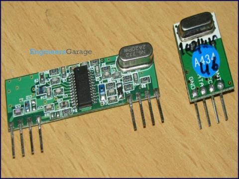
RF 433Mhz Transmitter/Receiver Modules
The following picture shows the Rx (left) and the Tx (right) Modules.
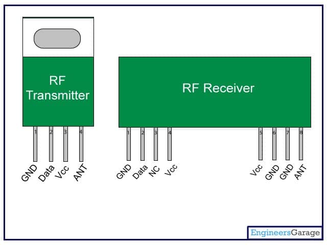
The following figure shows the pinout details of the above modules.
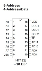
Encoder IC = HT12E
Decoder IC = HT12D
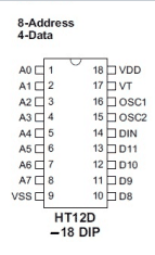
The above encoder and decoder ICs do the jobs exactly as per their assigned names that is encode and decode the bit information for enabling easy interfacing with analogue circuits.
After you have procured the above components it's time to put them together.
Assembling the Modules
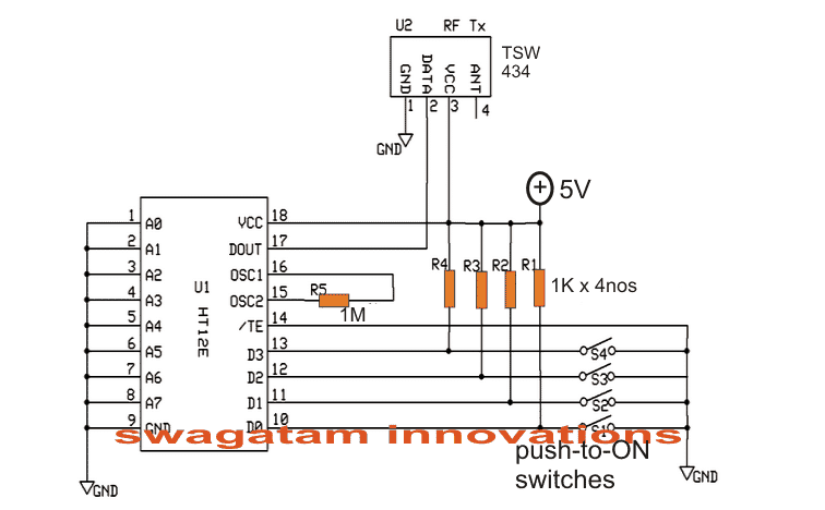
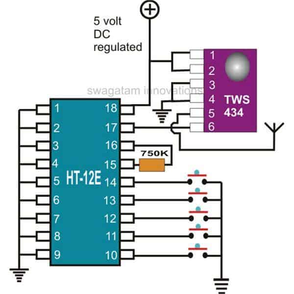
Configure the transmitter circuit by assembling the Tx (Transmitter) Module with the Encoder IC as given in the following circuit:
Next, assemble the Rx (Receiver) module with the decoder IC, as per the following diagram:
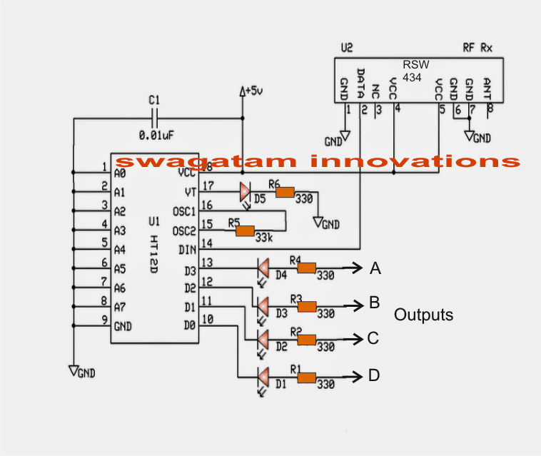
In the above Rx (receiver) circuit we can see that four of its outputs are terminated through LEDs at the points A.B,C,D and another output which is terminated via the VT pinout of the IC.
The four outputs A,B,C,D become high and latched in response to the pressing of the four push buttons shown in the Tx transmitter) circuit.
Pin13 switch of Tx influences the Pin13 output of the Rx and so on....
Suppose when output "A" of the Rx module is activated by the relevant switch of the Tx, it gets latched and this latch breaks only on activating any of the other outputs.
Thus the latch breaks only when a different subsequent output is rendered high through the Tx relevant push buttons.
The output from pin VT "blinks" momentarily every time one of the outputs A,B,C,D get activated. Meaning VT output can be used in case a flip flop is required to be operated.
The above can be very easily interfaced with a relay driver stage for operating any equipment such as a remote bell, lights, fans, inverters, automatic gates, locks, RC models etc.
How to Connect the Address Pins
The pinouts A0-----A7 of the Rx, Tx modules are very interesting. Here we can see them all grounded which creates an impression that these are of no use and are simply terminated to ground.
However these pinouts enable a very useful feature.
These address pinouts can be used for rendering a particular Rx, Tx pair uniquely.
It's simple, let's say for pairing the above modules we ensured that the address pins are identically configured.
Alternatively we could make the above pair unique let's say by opening A0 for both the modules. This will make the pair respond only with each other and never with any different module.
Similarly if you have more number of such pairs and want to make unique pairs out of them, just assign the pairs in the explained manner. You can do this by either connecting the address pins to ground or by keeping them open.
It means by rendering different configurations to the relevant address pinouts between A0 and A7 we can create a huge number of unique combinations.
The range of the above explained RF module is around 100 to 150 meters.
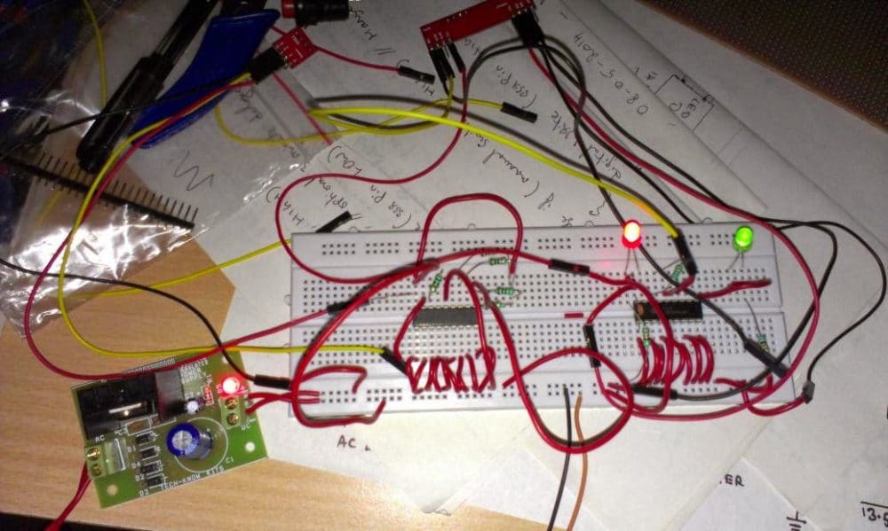
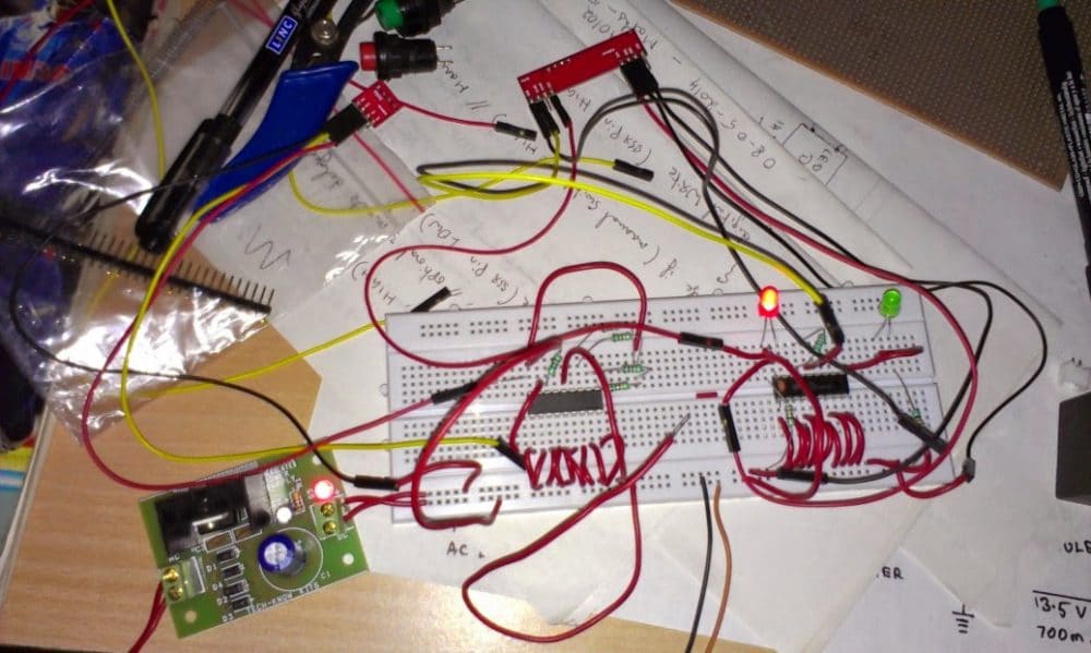
The above simple RF remote control circuit was successfully tested by Mr. Sriram on a breadboard, the following images of the built prototype were sent by him for reference.
Circuit Prototype Images
Making a 433 MHz, 315 MHz RF Remote Control with Relay Flip Flop
Building a hi-end remote control device using very few components today looks pretty plausible. The proposed remote control light switch circuit idea provides you with the opportunity of building and owning this amazing device through simple instructions.
Moreover the unit provides a 4-bit data to be exchanged between the transmitter and the receiver modules.
This Hi-tech remote control light switch enables you to control four individual lights or any electrical appliance for that matter from any corner of your house remotely using a single tiny remote control hand set.
Imagine switching a light, a fan, washing machine, computer or similar gadgets from any corner of your room without taking a step!
Doesn't that sound great?
Controlling a particular gadget remotely through a single flick of your finger definitely feels very amusing and amazing too.
It also gives you the comfort of doing an act without moving or getting up from a particular position.
The present circuit idea of a remote control light switch enables you controlling not only just a single light but four different electrical gadgets individually using a single remote control hand set.
Let’s try to understand its circuit functioning in details of the 433MHz Rx and Tx modules.
Transmitter (Tx) Circuit Operation
I have already discussed the wireless control modules in the above paragraphs, let’s summarize the entire description yet again and also learn how simply the stages may be configured into the proposed unit.
The first figure shows a standard transmitter module using the RF generator chip TWS-434 and the associated encoder chip the HOLTEK’s HT-12E.
The IC TWS-434 basically does the function of manufacturing and transmitting the carrier waves into the atmosphere.
However every carrier signal needs modulation for its proper execution, i.e. it needs to be embedded with a data that becomes the information for the receiving end.
This function is done through its complementing part – the HT-12E 4-bit encoder chip. It has got four inputs, which can be triggered discretely by giving them a ground pulse individually.
Each of these inputs produces coding which are distinctly different to each other and become their unique signature definitions.
The encoded pulse from the relevant input is transferred to the IC TWS-434 which carries forward the data and modulates it with the generated carrier waves and finally transmits it into the atmosphere.
The above operations take care of the transmitter unit.
Receiver (Rx) Circuit Operation
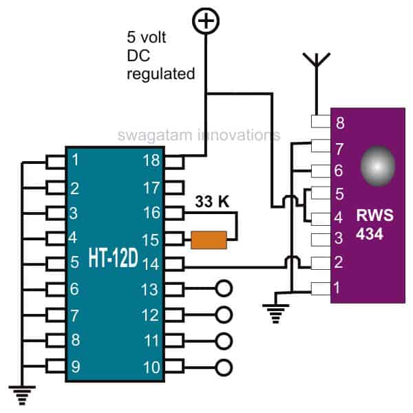
The receiver module does the above operations just in the opposite manner.
Here, the IC RWS-434 forms the receiving part of the module; its antenna anticipates the available encoded pulses from the atmosphere and captures them immediately as they are sensed.
The captured signals are relayed forward to the next stage – the signal decoder stage.
Just like the transmitter module, here too a complementing device the HOLTEK’s HT-12D is employed to revert the received encoded signals.
This decoding chip also consists of a 4-bit decoding circuitry and their outputs.
The received data is appropriately analyzed and decoded.
The decoded information gets terminated out through the relevant pin-out of the IC.
This output is in the form of a logic high pulse whose duration depends on the duration of the ground pulse applied to the encoder chip of the transmitter module.
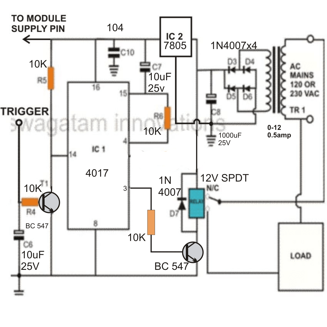
How to use a Flip-Flop Relay Circuit at the Receiver module Output
The above output is fed to a Flip-Flop circuit using the IC 4017, whose output is finally used to switch the output load via a relay driver circuitry.
One such flip/flop idea is shown you may construct four of them to access each of the generated 4-bit data discretely and control four gadgets individually.
Whether you use it as a remote control light switch or to control many more appliances……the option is all yours.


Questions & Answers
How to get motor off signal
When the remote button is not pressed, the motor will be off…
Can you provide a link for where to purchase Transmitter/Receiver modules that will work with your circuit? Reviews of the ones I have say that they do not work at all, or only work with an additional antenna. Others that come with an antenna also have mixed reviews.
You can easily buy them from amazon, and these modules definitely work. The reviews could be from the users who could not wire the modules correctly, or they could have been posted by the competitors of that seller.
I have followed your circuit (and several variations I found online) with modules from two different sources and a couple different HT12E and D chips. I had a neighbor who is an engineer look at my wiring and agree that I followed your circuit correctly. None of my tries has worked either with or without antennas. Can you advise me how to troubleshoot the circuit to find out what is wrong?
As you can see the circuits are very basic and should start working immediately.
Did you try with LEDs at the output for the receiver design?
Make sure the LED resistor ends are connected with the 5V positive supply.
If still it doesn’t work then possibly there could be something wrong with your connections somewhere, or the ICs itself may be malfunctioning.
Thank you so much. One of the address wires to ground was broken. My hobby is Model Railroading and I know only a little about electronics, but a 10 yr old neighbor who stops here a few times a week and asks how to do things, wanted to build a remote control. Now that I can do it, I will guide him to build one too.
Oh, that’s great! I’m glad you could finally get the circuit to work. All the best to you!
Hello, how can I increase the range to 2 or 5 km?
Hi, sorry, it is not possible to modify the range of this IC beyond 50 meters.
hi sir, I have completed , but i m facing range issue, range is only 3 to 5 meter, i used antenna also, but don’t know what happen with range, i tried with different rf modules, but range not increased. plz guide me what i do……
Hi Ghulam, this problem is specific to your RF modules and beyond my control, so it will be difficult for me to understand and solve this problem.
Please use the RF modules separately without any load, with LEDs only and check the response first…
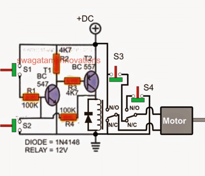
yes sir its working with npn transister, both relays are operating with remote now, once we press butten relay on and when leave relay off. now i want to add moter reverce and forward circut , in that circut with bc547 collecter you add 4.7k resister to positive and with s1, and on base 100k resister is connected with other side of s1, now these two points how to connect with 1st relay? for s2 bc557 emeiter is comnected with positive, base with 4.7 k resister connected with collecter of bc547. collecter connected with 100 k to s2, and other side is connected with negative, how to connect with relay 2? plz guide…… and while we are using remote, is it neccessary to add limit switch? because if remote butten pressed then moter will start, when leave moter will stop. plz guide me……
HI MR. Ghulam i hope you doing fine can you please share me your project details , im a student of electrical branch and im making the project Wireless water level controller using rf module and having alot of thing to understand about it if you will share me you project it will help me alot thanks
hi sir if you have made this project can you share it with me im also a student of EET and making exactly the same project it will be really helpfull if you share the details
That’s good Ghulam.
In the following circuit if you release the remote button, the motor will not stop, because the transistors are latched. That is why limit switches S3, S4 are required.:
Remove the S1 switch, and across the S1 switch points connect one relay’s pole, and N/O.
Do the same for the S2 switch points, by connecting the S2 points with second relay’s pole, and N/O.
Hi Ghulam,
I have an update!
The following circuit has a problem.
Suppose when the curtain is closed with the transistors latched, if mains power goes off and comes back then the latch will break and the motor will start reversing causing the curtain to start opening automatically.
Yesterday, I designed even a better remote controlled curtain open/close circuit which does not use any transistors rather only relays and can be configured with your remote control with perfection…
I will show you the circuit diagram soon.
yes sir, i tried with bc557, but relays continusly on, sir what about the antena how many turn required? which wire is best for long range?
Ok, you can try the following transistor configuration for a 12V relay:
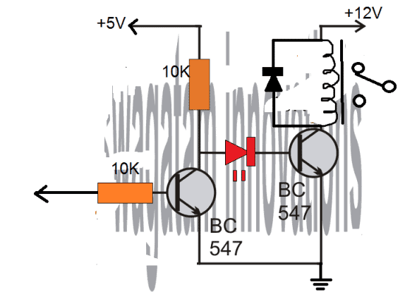
The LED can be removed and replaced with a short jumper.
The Tx module already has an in-built antenna which is enough for a range of 20 meters, for higher ranges you can use a 1 meter long flexible wire, any ordinary single core flexible wire will work.
The coiling of the antenna is not required, it can be a straight wire.
thank you sir, you always make easy for me. a lot of thanks, i wipp try my best to make. now i have 3 circuts, 1 is for ht12d 2nd is cd4017 and third is moter circut, i will make these 3 circuts combine, in this situation with 2nd circut cd4017, in this relay is nesseary or can we give power from bc547 to 3rd circut moter reverse forward. with limit switch…..
You are welcome Ghulam,
The 4017 IC circuit will not be required, you just have to replace the S1, S2 switches of the gate open/close circuit with the relay contacts of your remote receiver, that’s all.
sir like i required only ht12d circut, and at out put a and b i need to use relay, and from relay terminal give power to s1 and s2, thats it ryt?
Ghulam, you are right!
Connect separate 10k resistors with point A and point B.
Connect separate BC557 transistors at the other end of the 10k resistors.
Connect separate relays across collectors of the BC557 and ground.
Connect 1N4007 diodes across the relay coils.
Connect the emitters of the BC557 transistors with the positive supply.
hi sir, hope all is going well, sir i assembled as you guide, but i am facing issue, before i make water pump controler with rf module, i used ht12d and ht12e, and uc2003 ic, as password i connect all pins, 9 to 1, now in new project i changed password but receiver section catching signal from old one, even pins password is changed for both side, (rx and tx), where is the issue? i have green rf module.
Hi Ghulam,
Pin#9 must be connected to ground, only the pin#1 to 8 must be configured uniquely for different pairs of Rx and Tx.
The above configuration must be the same for the Rx and the Tx pairs.
If you configure the pin1 to pin8 differently for two different pairs then they must not interfere with each other.
Please try a different configuration once again and check the results.
However, if the two units are operating too close to each then maybe the systems can interfere with each other.
sir i tried and now its fine, but as you guide use to bc557 with relay, sir i give power to ht12d from 7805, signal led and output led is ok, but relay not on, how to make connection for 12 volt relay, bc557 emiter from where i can give positive? from 7805 out put or direct from 12 volt? plz guide
Ghulam,
Sorry, connecting BC557 emitter to positive is wrong for a 12V relay, it will not work…
If you are using BC557 then only a 5V relay will work.
For 12V relay you will have use two NPN transistors at the output of the Rx IC.
I will show you how to do it soon…
Thanks Ghulam,
If you are using a 12V relay, then the emitter of the BC557 must be connected directly to the +12V DC, not +5V.
+5V must be used only for the remote control ICs.
Relay coil must have a 1n4007 diode in parallel, cathode to BC557 collector and anode to ground.
Hi Swagatam
Thanks for clearing that up!!!! You are the best!!!
You are welcome Norman..
Hi Swagatam, In the above article with reference to the receiver circuit, you say the A,B,C,D become high and latched in response to the pressing of the push buttons of the transmitter circuit. That doesn’t seem right as you show the LEDs in those lines to be connected backwards. Also in another post you show the LED connected correctly and you are using a PNP transistor. I also posted on that page. Please confirm the outputs of the HT12D to be negative when triggered by the TX/RX modules.
Hi Norman,
I have replied to your previous comment in the other post, please check it.
Yes, there’s a typo in the above article, the term “high” must be replaced with “low” because as per the test results from one of the users the outputs A, B, C, D from the receiver are supposed to become low upon receiving a signal from the transmitter.
These relevant receiver outputs might get latched if the signal from the transmitter is selected to operate in a latched mode (flip-flop mode)