In this post I have explained about the making of a simple online uninterruptible power supply (UPS) which guarantees a seamless transfer of AC mains supply to inverter mains supply for the load, due to the absence of cumbersome transfer switches or relays.
What is an Online UPS
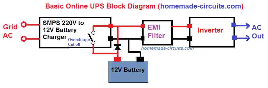
As the name suggests, an online UPS system stays continuously online, and never goes offline even for a split second, since the battery supply to the UPS inverter is held continuously connected, regardless of the mains AC situation.
During the period the mains AC input is available, it is first converted to DC and stepped down to the battery level.
This DC charges the battery and also takes precedence over the battery to simultaneously power the inverter due to its higher power rating than the battery. The inverter converts this DC back to the mains AC for powering the connected load.
In an event that AC mains fails, the stepped down AC to DC supply gets cut off, and the battery being continuously connected in line, now begins powering the inverter seamlessly, without any interruption of power to the load.
Online UPS vs Offline UPS
The main difference between an online UPS and an offline UPS is that, unlike offline UPS, the online UPS does not depend of mechanical changeover relays or transfer switches for transiting from AC mains to inverter mains AC during an AC mains failure (as shown below).
On the other hand, Offline UPS systems as shown in the below block diagram, rely on mechanical relays for transferring the UPS to the inverter mode, during the absence of mains AC supply.
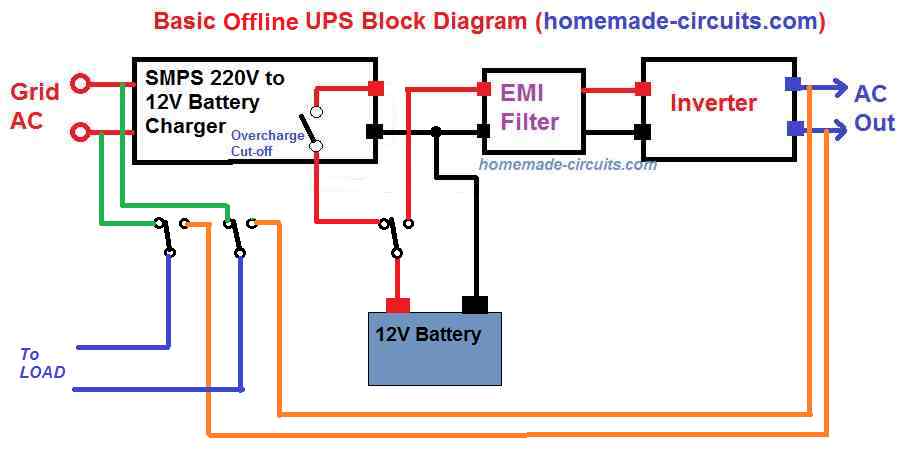
In these systems when mains AC is available the supply is directly supplied to the load via a set of relay contacts, and the battery is held in the charging mode through another set of relay contacts.
As soon as AC mains fails, the relevant relay contacts deactivate and switch the battery from the charging mode to inverter mode, and the load from grid AC to inverter AC.
This implies that the transfer process tends to involve a slight delay, albeit in milliseconds while changing over from the grid mains to the inverter main.
This delay though small could be critical for sensitive electronic equipment such as computers or micro-controller based systems.
Therefore the online UPS system seems to be more efficient than an offline UPS in terms of speed and smoothness, during the changeover process from grid AC to inverter AC for all types of appliances.
Update: Simplest and Effective Online UPS Circuit Diagram
The following circuit designed by me, shows a simplest online UPS design which will fulfill the function of a good online UPS, without any complex circuitry:
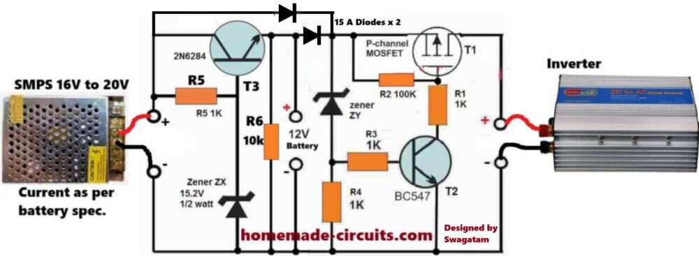
So basically, if you are not interested in the below explained elaborate online UPS circuit design, then you can go for the above simple design, which will nevertheless serve the purpose of an online UPS, safely.
The zener diode ZY determines the low battery cut-off level. Set and optimize this value to ensure that the inverter is turned off as soon as the battery voltage discharges below a certain unsafe lower value...
Online UPS/Inverter Circuit using Op-amps
As discussed in th above sections, making a simple online UPS actually looks quite easy.
We will ignore the EMI filter for simplicity sake and also because the inverter in our design will be a low frequency (50 Hz) iron-core transformer based inverter, and the SMPS would already include built in EMI filters for the necessary rectifications.
We will need the following materials for the basic online UPS design:
- A ready made Mains AC to DC 14 V 5 Amp SMPS module.
- A battery over charge cut-off system with constant current charger circuitry.
- A battery over discharge cut-off circuit stage.
- A battery 12 V / 7Ah
- Any simple Inverter circuit from this website.
Circuit Diagrams and Stages
The various circuit stages for the proposed online UPS circuit can be learned from the following details:
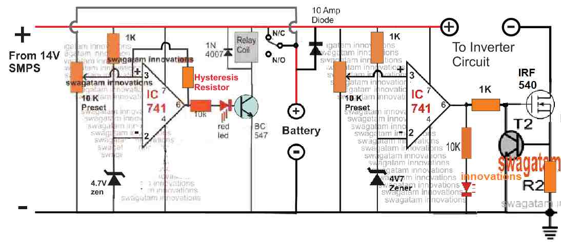
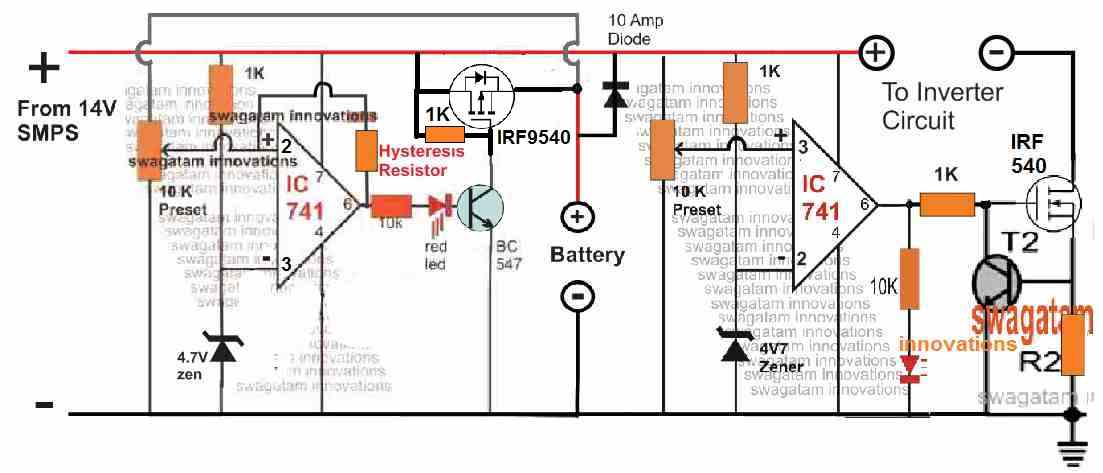
1) Battery Cut-off Circuits: The circuit below shows the very important battery over-charge cut off circuit, built around a couple of op amp stages.
The left side op amp stage is configured to control the over charging of the battery. The pin#3 of the op amp is connected with the battery positive for sensing its voltage level. When this battery voltage at pin#3 exceeds the corresponding pin#2 zener value, the op amp output pin#6 turns high.
Parts List
- Resistors are 1/4 watt 5%
- 1K = 3
- 10K = 2
- 10K preset = 2
- Current limit resistor = 0.6 / max inverter current
- Hysteresis Resistor = 47K or as per the experimented value
- Semiconductors
- Zener diode 4.7 V 1/2 watt = 2
- LED RED = 2
- Rectifier diode 10 amp = 1
- Rectifier diode 1N4007 = 1
- BC547 transistor = 2
- MOSFET IRF540 or IRF3205 = 1
- IC 741 = 2
- Relay 12V, 10 amp = 1
- SMPS 14V 10 amp = 1
This activates the relay via the BC547 driver transistor causing the relay contacts to shift from the N/C to N/O, which cuts off the charging supply to the battery, preventing over charging of the battery.
The feedback hysteresis resistor across pin#6 and pin#3 of the left op amp causes the relay to latch for certain period of time, until the battery voltage drops to a level below the holding threshold of the hysteresis, which causes the pin#3 to go low, and correspondingly pin#6 also goes low, switching off the relay. The relay contacts now switches back to the N/C, restoring the charging supply to the battery.
Over Discharge Cut OFF Circuit
The right side op amp controls the over discharge limit of the battery or the low battery situation. As long as the pin#3 voltage of this op amp stays above the pin#2 reference level (as set by the pin#3 preset), the op amp output continues to be high.
This high output at pin#6 enables the attached MOSFET to remain in the conduction mode, which allows the inverter to be switched ON through the negative line.
In an even that the battery is over-drained by the inverter load, the op amp pin#3 level drops below the pin#2 reference voltage, causing pin#6 of the IC to go low, which cuts off the MOSFET and the inverter.
Current Control Stage
The BJT associated with the MOSFET forms a current control circuit for the online UPS, which allows the battery to be charged through a constant current level.
R2 must be calculated to set the maximum current control level for the battery and the inverter. It may be implemented using the following formula:
R2 = 0.7 / Max Current
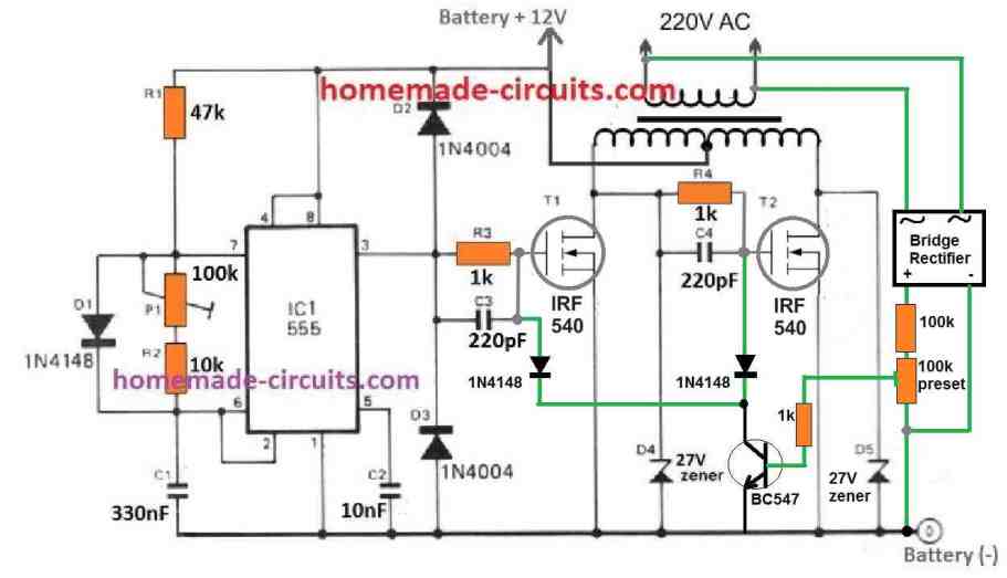
2) Inverter Circuit: The inverter circuit for online UPS system, which needs to be connected with the above battery controller circuit is shown below.
Parts List
- Resistors are 1/4 watt 5%
- 47K = 1
- 10K = 1
- 1K = 3
- 100K = 1
- 100K preset = 2
- Capacitors
- 330nF Ceramic = 1
- 10nF Ceramic = 1
- 220pF Ceramic = 2
- Semiconductors
- 1N4148 = 3
- 1N4007 or 1N4004 = 2
- 27V 1 watt zener diode = 2
- IC 555 = 1
- BC547 transistor = 1
- MOSFET IRF540 = 2
- Bridge rectifier using 1N4007 diodes = 1
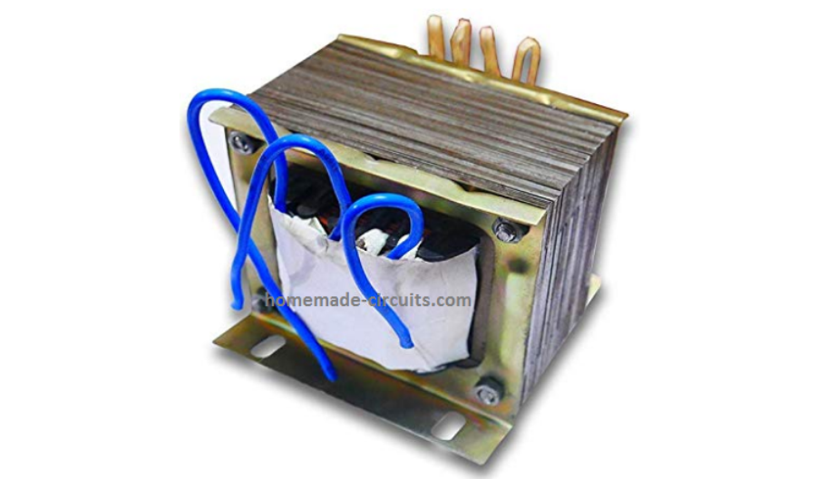
- Transformer 9-0-9 V 10 amp / 220V
We have selected an IC 555 based circuit for simplicity sake and also for ensuring adequate power output range.
This inverter will remain online as long as the charger circuit and the battery remains functional, and the grid AC mains is fed appropriately to the system via a AC to DC SMPS circuit rated at 14V, 5 amp, or as per the particular power rating of the system, which is fully customizable.
The BJT feedback across the gates of the inverter MOSFETs ensures that the output voltage of the inverter never exceeds above the safe level, and is fed in a controlled manner.
This conclude our simple online UPS circuit design, which ensures a continuous uninterruptible online power to any AC load, which needs to be functional without any interruption regardless of the input AC availability.


Questions & Answers
Hello – We have a paid power electronics project you can potentially help us with, Can you please contact me? Thank you, Saroj
Thank you Mr.Saroj,
Can you please send me the specifications of your project to my email ID. Let me check it, if I find it feasible, then we can discuss it further. My email ID is:
homemadecircuits
@gmail.com
Thank you for your very useful sharing!
I am a master student of an electrical engineering school. I am designing a simple UPS Online model for doing experiments on it. Do you have simulation data for this UPS online design project?
I really need to understand more deeply to be able to design a simple UPS online for my research purpose.
Hope you can share this design document.
Sorry, I don’t have the simulation data for the above circuits. I have tried to explain the working of the concepts in the above article….if you have any specific questions you can feel free to ask, I will try to solve it ASAP.
Can you provide me with the details of the SMPS you are using in the project? I tried searching but could not find the SMPS you mentioned in your post.
Thank you very much for that!
The SMPS must have a voltage adjustment preset externally. The current delivering capacity of the SMPS must be as per the specifications of the inverter and the battery.
OK, thank you
Hello sir, thank you for accurate answers, I want a 12V output UPS with 4 stage lead acid battery charger, current control with potentiometer ( current limiter in input for every AH of battery 7-200 AH ), discharge limiter of the battery, reverse polarity protection and automatic fan if necessary, please help me.
ruhollah, if possible I will try to design it…
so how can i schedule battery cut off without the use of software, just components for a notified battery cut off
In the first diagram, the battery will never get overcharged because the left side transistor regulator will always keep the charging voltage to the battery slightly lower than its full charge specifications.
For the low battery inverter cut-off the MOSFET and the BC547 transistor along with the ZY zener will take care of it.
Good day, I really enjoyed every step taken in this article or I call it lecture.in the quest to solve a problem with my ups that I came across this article. But my problem I believe will be resolve, I have 650va ups manufactured by blue gate. It stopped charging the battery but my little experience in electronics I couldn’t find the fault.i want to know which component that cause the ups to stop charging.
Thanks, I hope my question will be attend to.
Thank you Sunny,
A battery charger inside an UPS may have many stages and components, such as a relay or a MOSFET, or an op amp etc. Without checking these parts it can be difficult to judge the actual fault.
So you will have to open the UPS and check these sections of the charger to correctly figure out the fault.
hi I was searching for the right circuit to use as 12v router UPS (yours have 2 parts) i was looking for 1st part, to use without relay (except battery charging side) with VARIABLE CUT OUT (for lead acid or lithium) , over charging and discharging. i was thinking mosfet IRFZ44N AS SWITCH, from one source to another, pls give your exprt opinion
You want to replace the relay with a MOSFET? Please checkout the following modification:
Thanks for the feedback. Please provide average wattage required for the transformer, mosfet and battery as I definitely want to make this due to the daily loadshedding we are experiencing. Thank you in advance.
You can try any desired wattage for the transformer. I would recommend trying with a small 5 amp transformer first, if you succeed then you can upgrade to higher wattgae.
Try with a 9-0-9 5 amp transformer, 12V 7 ah battery, and a 14V SMPS.
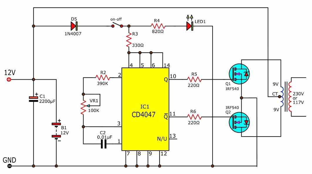
For the inverter circuit you can try any other simpler design using a 4047 IC such as this:
Hi, thank you for your quick reply. Can you please tell me what is the output wattage from the inverter? How do I increase the wattage? I want around 2 to 2.5kW/h to run my TV, router, Dvr, and computer.
Thanking you in advance
Sew
The output wattage will depend on the wattage of the transformer, the wattage of the mosfets and the battery Ah rating. You can try building this circuit only if you are an expert in electronics otherwise I won’t recommend.
Hi, can you provide me with the exact parts list and values. I live in South Africa and loadshedding is everyday. I want to use above circuit to power my router and tv… Looking for about 2kw/h for the inverter. Please also provide value for hysteresis resistor.. Please reply to my email address.. Thanks and namaste
I have updated the parts list.
But please try it only if you have thoroughly understood the working concept and are confident about it.
I made a pc board for this project if somebody wants the layout plus parts placement I can send it via email.
We have lots of load shedding here in South Africa and this will help with all the smaller electrical equipment
also to drive directly from the 12v output.
Hi CB
I am in Northcliff Johannesburg would like to try this, pls forward to me at
romeo.jagjiban@gmail.com
Hi, I’m also from South Africa, living in richards bay. Can you please email parts list and layout… Thanking you in advance
hi Brand
Can you send me pc board and layout
Thank you
Sir how do you put a feed back on ka3525 wile using a circuit of be 555 avlu741 as sine wave converter
Please show me the full schematic, I will try to solve it for you.
HAD ANOTHER QUESTION PLEASE
WHAT ARE THE VOLTAGE RATINGS OF THE CAPACTORS???
The voltage should be 2 times the battery voltage, higher than this will also do.
Hello Swagatam hope you’re doing well.
Please I wish to implement the circuit, how is the Hysteresis resistance calculated?
Do you have some precautions/recommendations for me or the circuit just works fine?
Hello Kenfack, the hysteresis resistor is best determined through some trial and error. It is basically to ensure that the relay does not switch ON/OFF quickly at the full charge threshold of the battery. You can initially use a 100K and check how long the relay remains latched and at what discharge point it restores back to charging mode. If you find it too quick, you can decrease the resistor value to 68K and so on.
However for exact calculations you may refer to the following post:
Opamp Hysteresis – Calculations and Design Considerations
THANK YOU VERY MUCH
Waouh thank you very much.
The project is awesome and great, I like it very much.
Thanks for everything!!!!
I’ll disturb you again please…
If you don’t mind I’ll like you to explain the functioning of the inverter circuit and the role of the bridge rectifier..
Thanks in advance
Thank you, The 555 IC generates a 100 Hz output which alternately switches the mosfets, and the connected transformer inverts the alternating 12V Dc to 230 V AC. The bridge rectifier converts the 230V AC to 230V DC which is stepped down by the resistors and the resulting DC is used for sensing an over voltage and cut off.
Thank you very much
Awesome posts, I just found your site.
I have 2 questions:
I’m in the US, and we use 110v at 60 Hz. What changes would be required for that? (Or do you have a similar place for US based diagrams?)
Is this modified sine wave output?
Thanks in advance!
Thanks, and glad you liked the post!
You can use exactly the same design as explained above even with a 110V source, since SMPS powers supplies are built to work with voltages as low as 85V AC, upto 285V AC.
However, the inverter transformer secondary side must be rated to produce 110V, instead of 220V AC.
The output is a square wave. To get a modified output you, can the second schematic from this article:
7 Modified Sine Wave Inverter Circuits Explored – 100W to 3kVA
mary chrismas , hope all in your family are ok
Merry X’mas to you too, thank you