In this post I will explain how to use this active PFC calculator for calculating high current, high PFC designs. In our example we will be using 230 VAC input and 3 kW output and Vout equal to around 390 V, and we will try to see how each resistor and capacitor gets calculated in a PFC circuit using the specialized IC UCC28180. So let us start understanding right away:
Purpose Of This PFC
We use this PFC because when we take power straight from the AC mains then the current becomes very ugly shape, it becomes sharp pulses and it puts big stress on the wiring, transformer, and the electricity company side.
When we add this boost PFC stage then we force the input current to follow the same smooth sine wave shape like the mains voltage, so this keeps the power factor very high near 1.0 and the THD becomes low and the AC line becomes happy.
Now the mains will not heat, your breakers will not complain and your whole 3 kW UPS will draw clean current from the grid, so this is why we put this boost PFC stage before our main DC bus.
Audio/Video Representation
The Active PFC Calculator
3kW Active Boost PFC Calculator (CCM)
1. PFC Parameters
2. Core Selection
3. Core Dimensions
4. Magnetic Material
5. Winding
What the Calculator Does
This calculator helps us because this PFC design always depends directly on many numbers like AC input voltage, DC output voltage, power, switching frequency, and selected ripple percent, so normally we would sit and do each formula one by one, but this is slow and confusing.
That means this calculator takes all our values in one go and then it shows the inductor size, duty cycle, average current, peak current, and even the required inductance in mH, and this helps us to pick the correct MOSFET, correct diode, correct choke, correct Cbus, and correct current limit.
When we use this tool then we do not guess anything, everything becomes direct and fast and so now anybody can design a proper boost PFC just by entering the numbers and pressing the calculate button.
Circuit Diagram
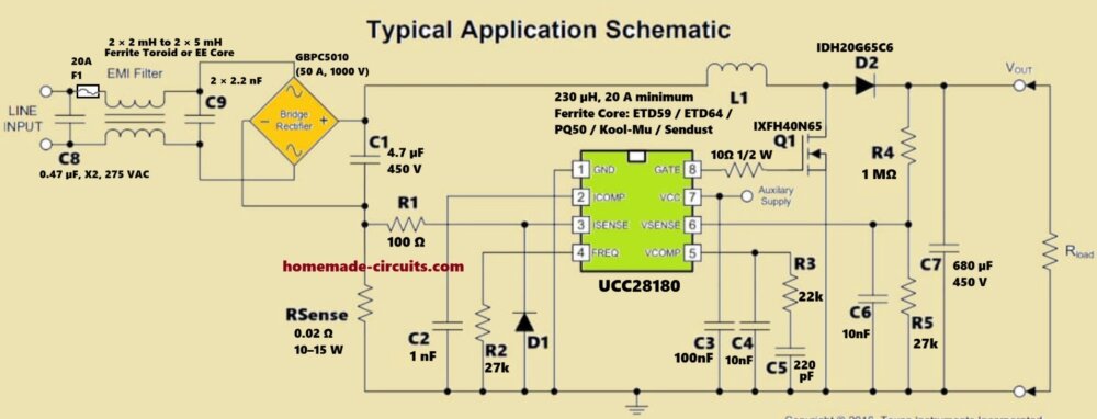
How it Works
Input Voltage Related Values
We first take the 230 VAC RMS and we convert it into peak value, so we do 230 * 1.414 and we get around 325 V peak. We do this because UCC28180 senses the peak shape indirectly through the scaling network at VSENSE. So we keep this value in mind for all coming calculations.
VSENSE Divider Calculation
Now let us talk about VSENSE pin. This pin sees a scaled down portion of the boosted 390 V output so that the controller can regulate the bus.
The internal reference at this pin is around 2.5 V, so we need to create a divider that turns 390 V into 2.5 V.
Now we choose Rtop as 1 mega ohm because we want to reduce current wastage, so we do simple divider math:
2.5 V = 390 * Rbottom / (Rtop + Rbottom)
Now we solve for Rbottom and we get around 6.6 kilo ohm, so we select 6.8 kilo ohm because that is a standard value.
So the divider becomes 1 mega ohm at top and 6.8 kilo ohm at bottom and this gives around 2.5 V at VSENSE when the boost output is 390 V.
VCOMP Compensation Network
Now we go to VCOMP pin, which gets an RC network for stability, and we normally use something like 22 kilo ohm in series with 100 nano farad and 1 micro farad to ground.
This combination filters the error signal coming from the VSENSE divider, and we choose these values because they give a correct phase boost and smooth loop response at this power level. off course we can fine tune but we keep these standard values as a safe starting point for a 3 kW boost PFC.
FREQ Pin Capacitor Calculation
Now we select the switching frequency and we choose 65 kHz because it is a good compromise for 3 kW. So UCC28180 datasheet gives a formula for FREQ timing capacitor and we apply the formula and we get around 1.2 nano farad.
So we select a standard 1.2 nano farad or 1.0 nano farad depending on availability which sets the switching frequency for the MOSFET gate.
ISENSE Resistor Calculation
Now we calculate the current sense resistor RSENSE. We have 3 kW power and 390 V output so average output current is around 3000 / 390 = 7.7 A.
But boost inductor ripple and peak shaping makes peak current much higher, assume around 30 to 35 A peak.
The ISENSE limit threshold inside UCC28180 is around 0.5 V so we do 0.5 V / 35 A = 0.014 ohm meaning around 14 milli ohm.
So we select a resistor like 10 milli ohm to 15 milli ohm with 3 W to 5 W rating or we use a metal strip resistor rated for high pulse.
ICOMP Network Calculation
Now let us talk about ICOMP pin.
This pin needs an RC filter to shape the current loop and the usual starting values are 2.2 kilo ohm in series with 4.7 nano farad and a 100 nano farad to ground.
These values stabilize the average current control loop which we can fine tune later, but these values work well for a 3 kW design. These components give us correct bandwidth for the inner current regulation loop.
Input Capacitor Calculation
Now we calculate the small input capacitor that sits before the boost inductor, and that capacitor is not for energy storage but for EMI filtering, so we keep around 1 micro farad to 2.2 micro farad rated at 400 V or more.
We do not use a big capacitor here because PFC does not allow smoothing of the input current and only add minimum capacitance to reduce HF noise.
Output Capacitor Calculation
Now we calculate the output capacitor at 390 V, here we want small ripple so we select around 470 micro farad to 680 micro farad at 450 V using two or three capacitors in parallel.
The required capacitance is based on the hold up time and ripple voltage, assume around 5 percent ripple.
We keep ESR very low so we select good quality electrolytic capacitors and also add a 1 micro farad film capacitor across the bus to kill HF spikes.
Putting All Values Together
- Now we see that VSENSE uses 1 mega ohm and 6.8 kilo ohm.
- FREQ uses around 1.0 to 1.2 nano farad.
- ISENSE uses around 10 milli ohm.
- ICOMP uses 2.2 kilo ohm and 4.7 nano farad and 100 nano farad.
- VCOMP uses 22 kilo ohm and 100 nano farad and 1 micro farad.
- Input capacitor is around 1 micro farad and output capacitor is around 470 to 680 micro farad. This collection forms the working RC network for the PFC controller.
Final Explanation Ending
So now we reach the end and we see that this whole UCC28180 PFC design is not complicated once we break it into small parts. We took 230 VAC input and 390 V output for 3 kW and we saw how each resistor and capacitor has one clear role.
VSENSE divider tells the chip what the real bus voltage is, ICOMP and VCOMP RC parts fix the current loop and voltage loop, FREQ capacitor sets the switching frequency, and ISENSE resistor decides the peak current limit.
When we choose these values correctly then the controller automatically keeps the input current in the same shape as the AC sine wave. So now we understand that this high power PFC circuit is only simple rules and simple formulas, nothing too complex....


Questions & Answers
WOW!
That is an awesome update to the calculator.
I spent a few hours more reading on your site and found the transformer design info in other places but having it all together is very convenient.
I love your site and thanks for all the good work!
Thank you! appreciate your feedback, hope it will solve your PFC design problems now…
How do I select an inductor for this 3kw PFC? That is the only thing missing from the calculator.
I have updated the calculator with more depth, please check it now…
can I use the calculator to design for 1 KW 400DC output?
Yes, you can!!
i want to design a 3KW Boost PFC which specification are as follow:
1. Input voltage = 240VAC +- 15%
2. Output voltage = 400VDC
3. Operating mode = CCM
4. Power factor = 0.99
5. Current THD = 5%
6. Switching Frequency = 50KHz
i want to design using DSP micro-controller, how can i tune PI value for voltage and current to maintain THD <5%.
Hi, The PI values cannot be determined from the specifications alone. They mainly depend on your boost inductor, output capacitor, current and voltage sensing circuits, ADC sampling rate and the DSP control algorithm.
Normally the current PI loop is tuned first to get a clean sinusoidal input current. After that, the voltage PI loop is tuned much slower to regulate the 400 V output without increasing the input current THD.
If you are using a TI DSP, then their digital PFC application notes and reference code provide a very good starting point for PI tuning.
If you can tell me which DSP you are using and your inductor and output capacitor values, I can suggest some initial PI gain values.
we are using dsPIC33CH512MP506 microchip controller. boost inductor 500uH and 1200uF cap.
Hi,
500 µH inductor and 1200 µF capacitor look OK for a 3 kW CCM boost PFC.
For the PI values, there is no fixed number. First tune the current PI until the input current becomes a nice sine wave. Then tune the voltage PI slowly so the 400 V output stays stable without increasing the THD.
If you are using the Microchip reference code, then that is also a good place to start.
Hello dear friend
Thank you for the content on your site
M.Khosravi
You are most welcome Masoud…