The following circuit of a temperature or climate controlled automatic fan speed regulator circuit was requested by one of the followers of this blog Mr.Anil Kumar. I have explained more about the proposed design.
The Design
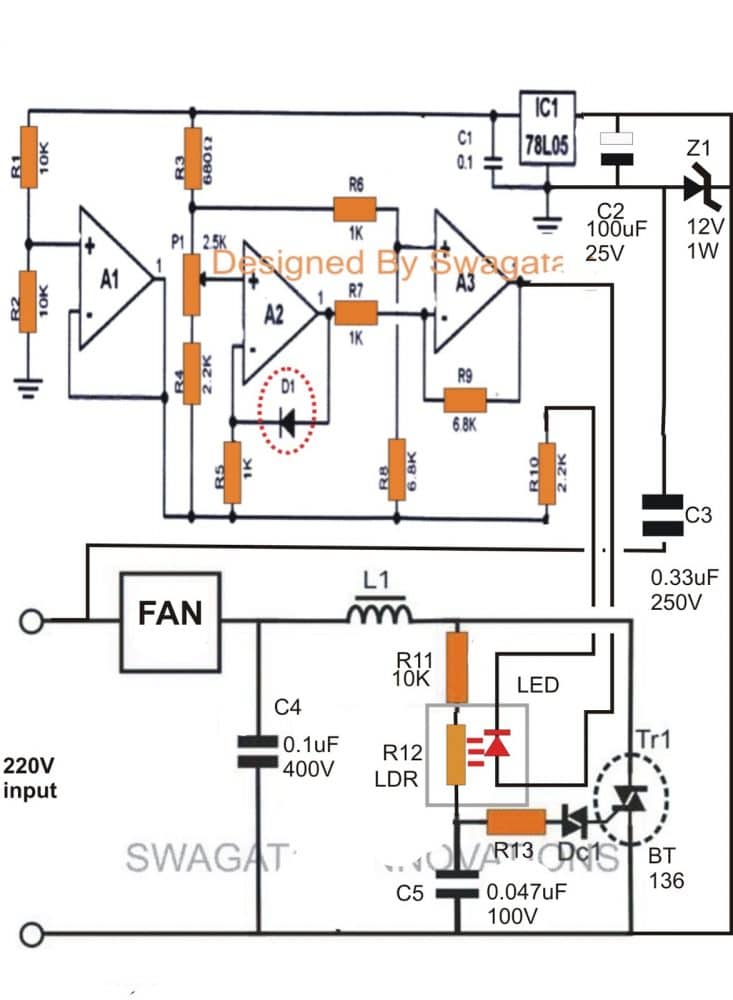
As can be seen in the given diagram, a very simple concept has been implemented in the proposed design of a climate controlled or temperature controlled fan regulator circuit.
A1, A2, and A3 are the 3 opamps from the IC LM324 which are configured as voltage comparators and amplifier.
The diode D1 which is a common "garden diode" has a very interesting "drawback", it changes its forward voltage drop by 2mV in response to every degree rise in the ambient temperature or the temperature surrounding it.
The above drawback of the device becomes our benefit here, because the feature here is exploited for sensing the ambient temperature of the premise.
The varying voltage across D1, in response to the varying surrounding temperature is effectively amplified at the output of A3.
The above amplified response is fed over an LED/LDR opto coupler, where the LED becomes the output load of A3.
Therefore the brightness of the LED varies proportionately in response to the temperature variations, it becomes brighter with increasing temperature and vice versa.
The above illumination falls over the built in LDR of the opto, which in turn varies its resistance according to the above information from D1.
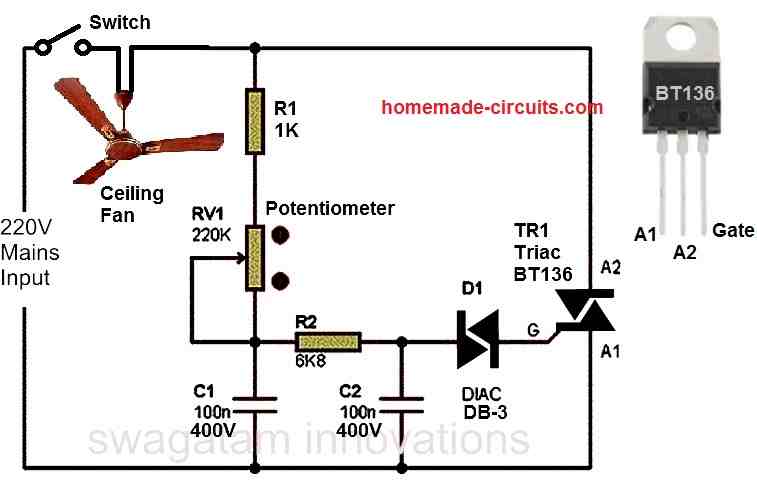
Since the LDR is fixed as the gate control resistor of the dimmer circuit consisting of R11, C5, R13, DC1 and the TR1, the voltage across TR1 starts regulating the mains AC in accordance with the fed LED/LDR response.
When the LED is bright (at higher temperatures), the LDR resistance lowers. allowing the triac to pass more current.
This increases the speed of the fan, and when the LED/LDR response decreases (at lower temperatures), the speed of the fan also decreases.
A compact power supply consisting of C3, C2, Z1 supplies the required filtered DC to the IC LM324 temperature sensor configuration for the intended operations.
Idealy P1 should be adjusted such that the LED just begins glowing at about 24 degree Celsius, initiating the rotation of the fan at the minimum level.
D1 must be kept exposed well outside the enclosure so that it is able to sense the fan breeze directly.
Circuit Diagram
WARNING - THE CIRCUIT IS NOT ISOLATED FROM MAINS AC...... BE VERY MUCH CAUTIONED WHILE BUILDING AND TESTING THIS CIRCUIT.



Questions & Answers
D1 = 1N4148
DC1 = diac DB-3
R13 = 47 ohms
L1 is not required, replace it with a link
can u help me how to rotate adjust fan forward and reverse direction??? i need it very urgent.
try this:
4.bp.blogspot.com/-G-E1CvLaU4U/UOfhAH6C0ZI/AAAAAAAACas/nsaEsevlY6k/s1600/reverse+forward+dc+motor+speed+controller+circuit.jpg
use BC557 and not BC547 as wrongly shown in the diagram.
hai sir we are going to do this temp controlled ceiling fan as our mini project can u help us
Hi Rajesh, if you do everything exactly as given in the above article it will surely work…
if you have questions you can put them here.
sir please give me a view about p1
It's given in the article explantion
Can you tell me the principle involved in the room temperature control fan…. in a simple way?
D1 senses the ambient temp changes which is amplified by the opamps, then fed to the dimmer circuit which converts it into corresponding varying fan speeds
Hi sir, do we need to provide vcc and ground , to the ic LM324??
Sir, do we need to give vcc and ground to the ic??
Nitesh, the Vcc/ground will go to the 78L05 output supply….pin4 to (+) and pin11 to (-) of 78L05 outputs respectively
Dear is this circuit is tested?
the two module were tested separately for different applications but not together, however it's recommended for experts only, newcomers will fail for sure
how change the setting for low temperature and high speed fan operation
Well thanks for helping us upcoming ambitious sudents.
Mine has the same principle( control of the speed fan using a DC power source with a Thermistor.
Could you please help me with that
thermistors are not sensitive enough to sense minute changes in ambient temperature, so I don't think it can be used for the mentioned application….the proposed 1N4148 as the sensor in the above article is a better approach.
But its possible to use a DC input circuit isolated from AC through an opto copler and Triac?
Could you help show me the circuit.
Well, i also needed a pin-out number of the 324 IC used. Cos im not so good in it.
yes you can replace the capacitive power supply with a DC adapter power supply, …..the circuit already employs an LED/LDR based opto so it is isolated from mains.
if you are not good with the basics then I would advise you to first learn all the basics and only then try this complex circuit
Can I use a transistor based optocopler too I got PC817 and I realised it was a transistor based isolator. I looked in the near by store and failed to find that particular one. Or maybe you could help me with the code..
I'm in the final process of building it on PCB board
NO, LED/transistor opto will not work here, only an LED/LDR hand-made opto will work, because the resistance of the dimmer circuit needs to vary in response to the LED brightness levels for the required fan speed control
sir i have 3 terminal ic78L05 (outout gnd and input) how to implement it in this circuit ?
C1 side is out…..C2 side is in
Sir will this circuit work i am making it.any headsup for me before making it ?
Gojo, this circuit will work if it's built if perfect understanding and care… and also by checking the stages step-wise before integrating together
first build the opamp stage, check it with a DC power supply, and make sure the LED changes its illumination when subjected to temperatures from 20 to 40 degrees C, proportionately
after that build the dimmer stage, confirm the dimming effect using a pot instead of the LDR…and then replace the pot with the LDR concealed with the oamp LED
all these will require a lot of optimization and understanding of the concept.
newcomers should not try this circuit
Hai sir,,
I need ac fan step by step regulator circuit..up to 4 levels sir
if possible i'll try to post it soon
Hello sir, may I ask what specific LDR/LED component you are using (name or code number)?
Hello Thieu, you can make an LED/LDR opto at home, using the following concept:
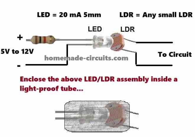
Just make sure to enclose the LED/LDR assembly inside a light proof tube, tightly.
Cảm ơn ngài, LDR tôi có nhiều, tôi sẽ làm theo ngài.
Thank you Thieu, no problem!!