In this post I have explained a simple, compact, 220V, 120V transformerless light chaser circuit which can be used for illuminating 220 V mains operated lamps or bulbs in a sequential chasing manner.
Main Technical Features
The chasing or running lamp effect can be altered by means of pot controls. The system can be used as a decorative lighting during festive seasons like in Christmas and Diwali. The idea was requested by Mr. Ashish.
As usual, the proposed Diwali, Christmas light chaser circuit is built around the ubiquitous IC 4017 which is a divide by 10 Johnsons counter/divider IC.
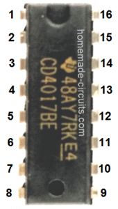
It basically has 10 outputs in the order 3, 2, 4, 7, 1, 10, 5, 6, 9, 10 pinouts which can be made to shift in a sequential manner, one after the other by providing voltage pulses at its pin#14.
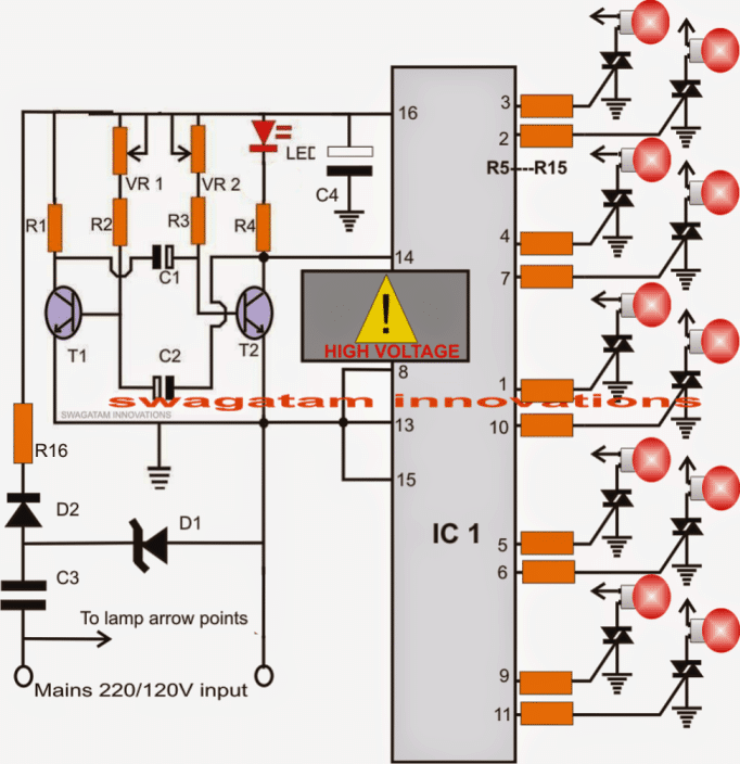
The above outputs can be either connected with LEDs for acquiring an illuminated chasing effect or can be terminated with triacs for driving 220 V mains operated lamps or incandescent bulbs in the same fashion, as shown in the diagram below.
Referring to the circuit diagram, we can see that the IC1 is clocked or pulsed at its pin#14 through a transistorized AMV stage.
Circuit Operation
This transistor astable multivibrator produces alternate high and low pulses at the collectors which can be witnessed by the blinking red LED.
With every high pulse or blink of the red LED, the output of IC1 sequences to the next subsequent output pin and continues to do this with every subsequent pulses at pin#14.
When the output reaches pin#11, the IC resets and the sequence returns to pin#3 for commencing a new cycle.
Here, since the outputs are terminated to gates of triacs, the triacs conduct with the same sequence illuminating the connected AC lamps producing a running or chasing effect.
The speed of this chasing or sequencing can be altered by simply adjusting the two pots VR1, VR2 appropriately.
The circuit runs from direct mains through a capacitive power supply and is therefore not isolated from lethal mains current, observe extreme caution while testing/handling the circuit while it's in an uncovered position.
Circuit Diagram
CAUTION: NO MAINS ISOLATION PRESENT....HANDLE WITH EXTREME CAUTION TO AVOID SHOCKS, AND FATALITY.
Parts List
- R1, R2, R3, R4, R5----R15: 1K
- VR1, VR2 = 100k
- C1, C2 = 10uF/25V
- C3 = 474/400V
- C4 = 100uF/25V
- D1 = 12V zener, 1 watt
- D2 = 1N4007
- R16 = 10 ohms, 2 watt
- Triacs = BT136
- IC1 = 4017
- T1,T2 = BC547
- LED = red, 5mm
220 V Lamp Chaser using IC 7413
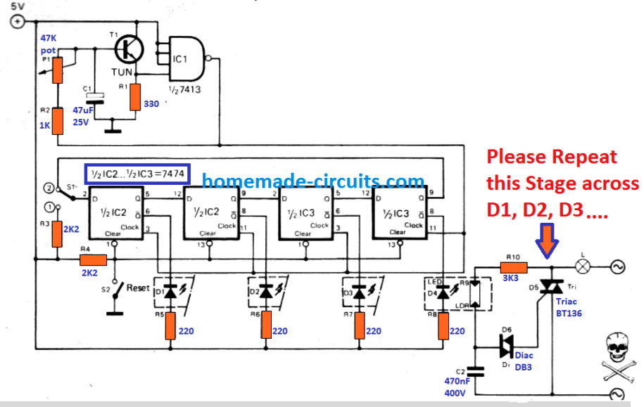
Through this circuit four 220V lamps could be used to illuminate in sequence, such that a 'running-light' effect is generated. The circuit is made up of square-wave generator (T1 , IC1), a shift register (IC2, IC3), and the lamp driver stages. P1 is used to vary the frequency of the square-wave from 0.1 Hz to about 10 Hz. The square-wave voltage is supplied to the clock inputs of the shift register.
When S2 is pressed the flip-flops get reset. The Q-outputs then turn into '0' and the Q-outputs into '1', all LED's are shut off and all the lamps are switched OFF. When S2 is released, S1 comes in position 1 causing the input of the register toturn into logic '1'.
Following one clock pulse, the input data of the flip-flop is carried to the output which illuminates the first lamp; S1 is now gets reset to position 2. From here on every subsequent clock pulse shifts the logic '1' on to the next flip-flop which in turn resets the last one, which causes the lamps to light up in sequence, producing a four 220V lamp chasing effect.
220V LED Chasing Lamp for Christmas and Diwali
The following design shows how a beautiful looking solid state LED light chaser can be created that will work directly from a 220V or 120V AC outlet.
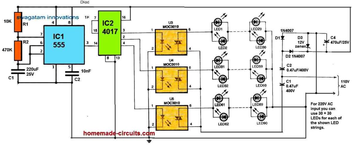
In this circuit, the IC 555 feeds a train of pulses at 0.5 Hz to the clock input of the IC 4017.
The IC 4017 responds to these pulses and outputs a shifting high logic sequence across its 3, 2, 4 pinouts to power the connected opto coupler sequentially.
The opto coupler outputs can be seen configured with strings of LED lamps which illuminate sequentially in response to the opto coupler conduction, directly from a 220V AC input through a transformerless power supply.
The MOC 3021 ICs actually include a zero crossing detector, to eliminate the mains AC current surge on the LEDs. This ensures that the LEDs never burn due to sudden current surge.
The opto couplers also ensure that while sequencing the switching action does not generate RF noise.
This simple transformerless LED chaser circuit can be effectively used for creating decorative LED string lights during festivals like Diwali and Christmas.
The sequencing rate can be changed by altering the value of the 220uF capacitor associated with the 555 IC.


Questions & Answers
if possible I would like a circuit to simulate flame
thanks
For simulating flame you will need the IC 4017/IC 555 circuit and 10 LEDs….
Sir input is 4ma to 20ma there is no input voltage because input current comes from current isolator
Out put is 0v to 5v out put current is max 5ma
Santhosh, I mean to say how much voltage and current are at the input which you want to boost?
Sir can you please give a circuit for converting DC 4ma to 20ma TO
0v to 5v DC thank you
Please specify what will be the input voltage and current, and what will be the output voltage and current.
Sir please tell how to modify the lamp chaser circuit using cd4017 for 20 lamps if possible or using any other ic thank you
I have an 18 LED chaser circuit, but not with lamps.
Sir I have send circuit to generate pulse of 12v dc having one second duration when ac power in on to your email contact@homemade-circuits.com can you please check that for any modifications thank you
Hi Santhosh,
I did not find any email from you.
Sir I have to really appreciate for your wonderful work giving information freely that has taken mostly many years to learn if possible please share your cell number thank you
Thank you Santhosh, sorry I can be contacted only through this website and I prefer discussing through website comments only.
Thank you so much sir for the circuit for switching 4 ac bulbs one after another sequentially
Sir I have tried one circuit that will give a pulse of 12v amplitude with duration 1 sec only at the time of AC power switch in on to get another similar we have to off and on again if you give your email I can send the circuit picture and please suggest any modifications thank you
Santhosh, you can send it to
contact
@
homemade-circuits.com
Sir can you please give a circuit for 4 AC lights should be on in sequence 12341234 like that only one bulb should be ON at a time thank you
Hi Santhosh, you can try the first circuit from the above article. Since you want only 4 lamps, remove everything from pins 1, 10, 5, 6, 9, 11. After this disconnect pin15 from ground and connect it to pin1
Sir the circuit needed is it will generate 12v pulse for 1sec duration only when ac is appled to produce another pulse we have to switch on and ON you have answered I am also trying thank you
I don’t have this circuit at the moment, you can surely try it and let me know the results.
Just make sure that you reply under a related article.
The above article is about Diwali, Christmas projects so not the right article for discussing this topic.
Sir thank you so much for the reply I will buy one smps power supply
You are welcome Santhosh!
Sir can you please give a circuit to produce 24v dc 1Amps without using transformers thank you
You will need an SMPS circuit for that. Other options using capacitor is not efficient. You can easily buy one ready made smps unit and then open it to see the parts and the circuit idea.
Sir can you please give circuit to produce a pulse of 5v amplitude for one second when AC power is on only one pulse another similar pulse will
produce only if AC power is switched off and on again that is there is no pulse if AC power is applied continuously thank you
Hi Santhosh,
Getting a pulse when AC is switched OFF looks difficult to me. I do not seem to have the idea at this moment, so can’t suggest a circuit. If I happen to get the idea I will surely let you know.
Can you pls. Explain the circuitry or what chip is used to create this different patterns i tried everywhere but all in vain(that black box in diwali lights).
Those are Chinese made embedded specially programmed chips, probably not available readymade in the market. You will have to program it on a microcontroller Ic and then you can use it for the purpose.
can I use only 5 outputs and ignore the rest. that is, I use only pins 1234&5
yes you can, just make sure to connect the 6th pin with pin#15…pin#15 should be disconnected from the ground and connected to the 6th pin
Hi, please tell me what kind of programming do you plan to implement, by the way if it's too complex then you may have to go for a microcontroller design.
also please specify, for music trigered RGB what kind of mixing do you intend to have??
dear brother i need how to design led running in different styles eg forward, revs,waterflow,
Pratheesh, that will require a micrcontroller, can be difficult using an ordinary circuit.
where to buy 8mm led in whole sale
from Lamington Road in Mumbai
Hi, Swagatam Majumdar.
I start a business as a wadding planar. For that I need to decorate the place with lights. Because of I am new in this business, I have to take the others lightning set and give them too much rent as a return. Now I decide, make my own lightning set with many varieties. but I know a little about this led circuit, and I can't find information as much as I need over the Internet. I hope you can help me with this. So please let me know if you can. it's really important for me
Hi Moseur, If you provide with all the technical specification that you require for the lighting, I may try to suggest….
but make sure the lighting pattern is not complex…
Common ground line means ….Neutral connection
the line which may be connected with the right side pin of the triac/SCR, it could be phase or neutral whatever but this line should be also connected with the negative of the circuit….this will make the circuit extremely dangerous to touch and therefore caution will need to be maintained.
If we use transformer input voltage 12v 1A to ICS…and 230v to bulbs & Triac…it will work ?….
yes it will work but make sure to connect the circuit negative with the SCR or triac common ground line.
Can I use readily available LED chain/string in the market which is equipped 474k 400v cap transformer-less power supply within a small thin box without any filtering electrolytic capacitor. If yes Is any OpctoIsolator like MOC3021 required?
Can I use any other SCR like BT169 or MCR100 instead of BT136 if yes which pin to what ?
In BT136 is PIN T2 to neutral T1 to LED chain one wire and other wire of LED chain to LINE(phase) of 220v AC. is it correct or T2 to Phase…
You must build exactly as shown in the diagram, I cannot suggest or recommend some other unknown circuit integration with the above circuit.
BT136 center pin goes to the load, left side pin to ground….and the right side pin is the gate
Can you please tell me how can I connect two CFL bulbs in Christmas start which lights one at a time
I'll try to upadte the details in a new article soon!!
50 led in series on one channel……..
Ok you can do it, but you will have to use a 0.47uF/400V capacitor at the junction of all the led strings, and the other end of the capacitor to one of the mains inputs….the other mains input will connect with the all the points marked ground in the circuit and the triacs
50 led in series on each channel
Hello sir how i can run the led in above circuit as i know that the circuit is designed for for 220v bulbs but by making some changes can we run led on this circuit if yes then how many leds can run in series
basit, how many LEDs do you want to run on each channel
Sir, can i use ic 4028 and 4516
sorry no, only 4017 or 4022 would work here