In this article I will elaborately discuss a simple to built yet awesome 1000 watt amplifier circuit, which could be easily upgraded to achieve upto 2000 watt output. It uses relatively fewer components and could be quickly set up for getting a massive 1000 watt power output on any 4 ohm, 1kva loudspeaker.
This circuit was sent through email by a dedicated enthusiast for publishing in this website
Introduction
The power amplifier discussed here is a 1000 watt Amplifier.
This amplifier works extremely well for pretty much any application that needs High power, high clarity, minimum distortion and outstanding sound.
Good examples of this could be Sub-woofer amp, FOH stage amplifier, 1 channel top notch surround sound amplifier etc.
The amplifier features four key stages of amplification.
Let's begin by investigating each one stage with full detail.
The Error Amp
The first stage is actually an asymmetrical balance input error amplifier circuit.
This is a layout, that enables a single differential stage and also a balanced input supply.
An unbalanced source can be utilized in case either the inverting or non-inverting input is linked with the ground line of the signal.
Now let's discuss exactly how every single transistor within this stage operates collectively.
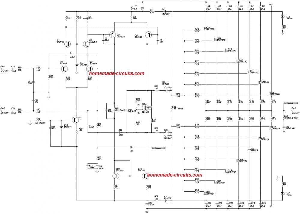
Q6, Q7, R28- R29, and help to build this important differential error amplifier.
This stage utilizes the transistor collectors with a cascode type of load. Q1, Q2, R13 and ZD1 constitute the cascode stage. This stage supplies a constant 14.4 volts to the collectors of Q1, 2.
R42, R66, Q23, ZD2 and C19 work as a constant current source, that resources 1.5 milliamps to the 1st differential stage.
Together these stages function as the first stage of the amplifier and essentially determine the way the entire amplifier is biased from start to end.
Voltage Amplifier Stage
This specific stage is designed for delivering the maximum possible voltage amplification required for the next stage, in order to switch the output stage with 100 % power.
R3, R54, R55, R40, Q3, Q4, Q24, Q25, C2, C9, C16 structure the 2nd differential voltage amplification stage. Q54 and Q55 work like a system which is called current-mirror load for the second differential stage.
This fundamentally pushes this stage to uniformly share the current acquired from R36, which can be around 8 milliamps.
The rest of the parts, particularly the capacitors work as local frequency compensator for this stage.
Bias/Buffer Stage
Q5, Q8, Q26, R24, R25, R33, R34, R22, R44, C10 does the job of Biasing and buffering, and hence the name bias and buffer stage.
The primary objective of this stage is to supply the MOSFET Gates with a constant and reimbursed supply voltage. And also to add a high impedance layer to the Voltage amp stage from the high Gate Source capacitance.
Without having this stage could certainly cause the frequency response and slew rate to become very bad.
However, the problem with this is the incorporation of an additional stage, a supplementary dominant pole across the amplifier's feedback loop.
The Output Stage
This stage switches the voltage produced in the VAS and supplies the full current necessary to operate 8 or 4-Ohm loudspeakers. 2-Ohm loudspeakers could be applied for some time, occasionally.
Actually I have checked this 1000 amplifier beyond 1600 watts RMS straight into 2 Ohms sub woofers. However I wouldn't encourage you to do this for any long term application.
Circuit Diagram
Power Supply Specifications
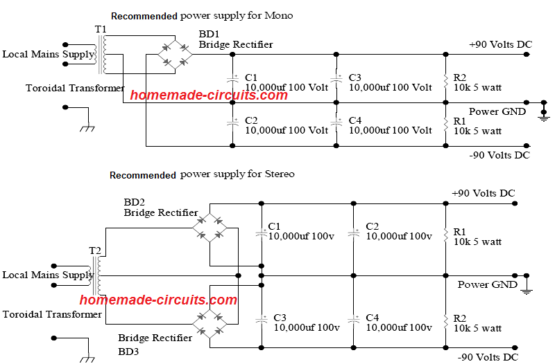
The power supply elements for this amplifier are as given in the following paragraphs. It is for a single Channel only.
1 x Transformer rated at 1000 watts. Primary windings are supposed to match your house AC supply. eg: for India and Europe the primary winding should be at 240VAC rating.
The secondary windings of the transformer should be rated as follows.
2 x 65 volts AC at full load.
1 x 400 Volt 35 Ampere, Bridge rectifier.
2 x 4.7K 5-Watt ceramic resistors
Lowest filter capacitor specifications can be 2 x 10,000uf 100 volt electrolytic.
Best value could be 40,000uf per supply rail.
Testing and Set Up
It is strongly recommended that you test the functionality of the amplifier right at the begining in order to ensure it really is performing correctly.
This can be accomplished by soldering a 10-Ohm ¼ watt resistor between the output of the amplifier and one end of the 330-Ohm 1W resistor used as R38
By doing this we link the feedback resistor R37 with the output of the buffer stage.
This basically bypasses the output stage and converts it into an extremely low powered amplifier, that can be freely analyzed without destroying the costly output stage.
Once this is done, next attach the +-90 volt supply to it and power it ON.
Make sure to have 4k7 Ohm 5-watt bleeder resistors soldered across the power supply filter capacitors.
At this point hoping nothing is smoking, using a multimeter on V range, measure the below shown voltage drops around the following resistors. In case they read close to the shown values within a range of +-10% then you could be positive the amplifier is ALRIGHT.
R1 = 1.6 V
R2 = 1.6 V
R3 = 1.0 V
R55 = 500mv
R56 = 500mv
Offset voltage at R37 might read a 0 volts, but also could be as high as 100mv.
Final Testing with Loudspeakers
Once you have completed the inspections, make sure to switch OFF power and take away the
10 Ohm resistor.
Thus we now have arrived at the stage where we should execute a maximum test out on the amplifier module.
There are still some inspections that must be carried out initially.
• The Drain pins upon all the output devices have to be inspected for socket to the heat sink.
• The power supply wiring may be examined regarding right polarity to the PCB.
• The Multi-turn pot P1 may be flipped back to 0 Ohms, to ensure that a reading of around 4.7k is achieved across the Gate and Drain pins of Q8 IRF610.
• While connecting the power supply, make sure to include 8 amp fuses placed on each of your power supply supply lines.
• Link up a multimeter on DC volt range to the output of the amplifier.
Alright given that you might be satisfied that this 1000 watt amplifier circuit is set up accurately, now connect power by using a VARIAC for those who have access to one, or else simply energize the amplifier through the given power supply
Checking out the voltmeter you can expect to see something around 1mv to 50mv offset (leakage) voltage.
If it is not seen then switch OFF the power supply and reexamine your work.
In case everything is alright switch off the system and with a fine screwdriver fine-tune P1 for the biasing of the output stage.
However initially attach the voltmeter around one of the output stage Source resistors with the help of Alligator clips.
Now once again switch ON power to the amplifier and gradually fine-tune P1 while examining the voltmeter, for a reading of 18mv.
After this, check across the remaining portion of the Source resistors and trace out the one, that has the largest value, and fine-tune P1 until 18mv is measured on the voltmeter.
Next, hook up a loudspeaker and music input to the amplifier and using a CRO for those who have one analyze whether the waveform is tidy and without any noise and distortion or not.
In case you do not have a CRO and Signal generator, hook up a pre-amp and loudspeaker and very carefully listen to the output quality. The output sound ought to be extremely clear and vibrant.
That's all, now enjoy! You have just assembled yourself and outstanding 1000 watt power amplifier which could be used for achieving a throbbing sound with a mind boggling power output...
Another Interesting Design
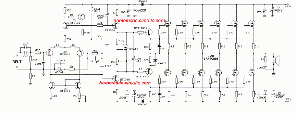
Here's another cool easy to build 1kva power amplifier circuit, which can be quickly built and implemented.
It is actually a 500 watt design but the power could be boosted to 1000 watts by suitably increasing the number mosfets or replacing the mosfets with higher rated variant.


Questions & Answers
Sir please send me thee diagram PCB desine clear
Yasir, Please see just under the first diagram.
Good Evening Sir,
I am a university student in kenya and am trying to implement this project for fun and learning sake. I would like to inquire, if am to incorporate a Bluetooth and usb module into this where would I connect their inputs to and how could I cycle which of the 2 plays back. I would be grateful for any kind of feedback
Hi Derrick,
Sorry I don’t have much idea about this topic!
hello Sir, if i change the power transistor to a more higher rated power mosfet transistor? do i need any modifications even if will used the same voltage for the supply?
Hi Soy, yes that may be possible. Alternatively you can achieve the same by increasing the supply voltage
Hey buddy,
There are examples of wgat you require online. Yes you could connect them into its input. But check output is with the correct requirements of the amps input.
The component list of the amp which includes the transformer would cost quite a bit of money. Work on something smaller first. Both amplifier and the Bluetooth. Perhaps also build yourself an voltage and current regulator to go with the power supply after the caps and rectifier. Speaker protection etc.
I’ve been to Kenya really enjoyed it. Such a lovely country.
Thank you Sir Swagatam because i’m planning to replace it with a Njw0302 and complementary.
Hi Soy, the mentioned transistor is a PNP BJT, while in the circuit it is N-channel MOSFET, so I am afraid your transistor won’t work in this application.
thank you Sir..
Very nice but am wondering 2 things.
First your secondaries are 65 volt each. Are these wired to give you 130 volts or wire to double the current?
Second. What is the current you’ve used to power the circuit?
Thanks, yes being a dual supply the total voltage will be 130 V, higher voltage will mean lower current to be used and vice versa. You may divide the wattage with the supply voltage to get a rough idea regarding the current requirement.
Do you have a parts list?
Its a little hard to properly read the components
Please see the download pdf link just under the diagram
I noticed that part after i posted. Thanks man.
Btw Am curious if you wanted 2 channels am I right to say the transformer would need to be double the power?
Yes the transformer will need to be 2 times more powerful
Just the current or the voltage ?
BTW is the input stereo variant or mono?
Only current, not voltage. It is a single channel, mono circuit, you will need two such circuits to get a stereo output
okay that makes sense just wondered if they’ll be an voltage drop greater by using 2 channels.
Which part of the input is GND?
Q23 ???
dimanakah letak skema r42 r66 Q54 Q55 TERIMA KASIH MASTER
I dont actually see the voltages of the caps nor the wattage factors of the resistors. I believe both are very important. Also the symbols dont match when looking at the PCB.
Thought id point these ones out.
all resistors are always 1/4 watt except the 0.22, which are 3 watt. All capacitor voltage must be two times the supply voltage (2 times of the single supply value))
You deleted my response?
If it were the cause that capacitor should be double the voltage then the PSU PCB wouldn’t be 100 volt when voltage supply is 90 volt right? It be much more. The voltage of a cap needs to be greater than the voltage yes otherwise it will short out. But in terms of what cap is required its based upon voltage and the UF of the cap. Purely on the basis of providing the right frequency of the circuit.
There are some standard rules and margins in electronics that must be followed. For a 90 V supply the capacitors must be rated at at least 150 v, if they are connected directly across the supply rails. It is to ensure maximum safety and long life for the capacitors. It depends on the user if they want to follow it.
That doesn’t mean the internal capacitors also should be 150V, they can be rated lower than 90 V or even 50 V depending on the various dropping netwirks such as resistive dividers and zener diodes, associated with them
That I get. Ive always known the caps are above the voltage of the circuit voltage in that part.
Not just above, 2 times above as a rule of thumb.
And anyway, as an example a 16V capacitor and a 63 V capacitor will have almost the same dimensions and cost, then why do we need to go for a 16 V capacitor?
I get that but am seeing on your PSU the caps are 100 volts. So is it because you have 2 caps?
Actually it is not my design, it was contributed by another author. 100V is absolutely dangerous. At 90 V the capacitors should have been at least 130 V or higher.
Hi sir,
We appreciate your efforts but how could I know or calculate the power of a torroidal transformer in case it has no readings on it if am to use in a power amplifier?
Thanks….
Hi Kakooza, you can check it by feeding 220V through the AC side and measuring the low voltage AC with a meter on the other side. If 220V side is not known, identity the same by applying 220V randomly through a 220v series bulb. The bulb will not glow when the 220V primarily wires are correctly identified.
Thanks sir
Bt I meant how to know the current ratings of the transformer (either 10A, 25A…..like that) because with Voltage I can measure.
I need an idea how to measure transformer current (output current) with a Clamp meter
You can measure the current rating by directly connecting a high current AC ammeter across the transformer secondary wires for a couple of seconds
Hi sir I am trying upgrade a power amplifier from 250:rms a channel,the out voltage is 90,16 MJ 15024 and 16 MJ 15025 transistor it’s a homemade amplifier,can this amplifier be upgraded?
Hi Adrian, you can probably try adding more number of transistors in parallel.
Hello sir,
What is the difference in performance between the two above power supply designs and which one best suitable for use in a BJT power amplifier?
The difference is written on the diagrams.
The lower design provides better separation between the channels and therefore improved stereo response
Dear sir, please sir my audio power amplifier now shuts down light in the house, when the amplifier is powered.
It wasn’t so before.
Please sir, what could be the problem of the power amplifier?
Dear Godfrey, your amplifier could be drawing huge amounts of current, due to some internal fault or due to shorted MOSFETs
what about the protection circuits…like speaker on delay, dc detect, overload detect…etc
all those will need to be added externally.
Hi Mr Swagatam.
What are the dimensions of this board
Hi Ike,
If the dimesions are not given in the download link, then I think you can find out the dimensions yourself by comparing the size of the MOSFET pads and other components on the PCB, or the PCB designer will be able to figure it out for you.
Is this surround sound boards exist in the market?
How do you determine 1000 Watt power? The output MOSFET rating is 200V 20A and 12A. There are 7 pairs. Shouldn’t it be Vcc * 12A *7 = 90V * 12A *7 = 7560 VA?
MOSFETs are connected in parallel, so the current multiplies, voltage remains the same at 90V
yes, my question is why is it 1000 watt ampifier when the power from output stage MOSFET is 7560 W?
It is 1000 to 2000 watts
higher number of MOSFETs ensure lower heat dissipation on the mosfets and therefore smaller heatsinks.
Current is being drawn from the speakers, @4 Ohm ~ 25A. 25 times 100 = 2500Peak to peak, x .7 ~ 1500. regardless of theroretical fet capability.
Hi,
This Looks Like a very Nice design and I want to try and Build One.
1) What is the size of the PCB?
2) Do you have a Power Supply Design that goes with it?
3) Can it be powered by a SMPS power supply without negative effects?
Regards
Hi, thanks, and glad you liked the design.
You can download the details from the download link for getting the PCB details
You can use an SMPS with this amplifier without issues, just make sure the current and voltage of the SMPS are compatible with the amplifier specs
Thanks so much for the circuit. but i want to know if you have tested it and which power supply can be used for the second circuit.
Glad you liked the circuit. I have not yet tested it. You can use the same power supply for the second design which is used for the first design.
Hello! I guess this is a class A amplifier (by looking at the schematic)
How do you manage the heat dissipation on this beast? I want to make a amplifier for my 1500 watt subwoofer and I am completely new to this amplifier stuff (I am quite familiar with electronics). I just want to make sure that class-A amps are “coolable” and would not produce IMMENSE amount of heat when attached to a chunky heatsink.
Hi, My knowledge about amplifiers is not good, so I am unable to identify whether this is a Class A amplifier or some other class. Moreover this design was contributed by an external author therefore I do not have every little details about this circuit…..However whoever designed this circuit wouldn’t have designed it like a class A amplifier, so it needs a closer inspection.
Hello Rodolfo,
You will have to put little effort and copy down the parts from the schematic given in the following link. If you have any problems let me know:
https://www.homemade-circuits.com/wp-content/uploads/2019/09/1000-watt.pdf
Thanks Soo much for this sir, but how can I get a clearer circuit diagram, this one seems blurred
Thanks
You are welcome Aminu, there’s a download button just below the circuit diagram, you can use it to get a clearer diagram.
I want an amplifier circuit diagram using 2sc5200 and 2sa1943 at a voltage of 120vdc+ and 120vdc- .thax my big brother swatam.and I invite you to come in Uganda ????????
Hi Norman, Presently I do not have an amplifier circuit using 2sc5200 and 2sa1943, but I will try to find it, if I do will surely let you know.
Can i use any type of mosfet on irf510 which is not amongst the equivalent
Yes you can use it.
hello sir, i am a audio enthusiast. i want to build my own 1000watt class A amp. but i don’t want to loss so much on the errors. i found that some people are using njw mosfets or 2sc 5200/ 2sa 1943. please tell me, what i can do ?
give me the scamatic, which i can build.
Hi Nilanjan, Class A amplifiers can be very inefficient in terms of heat dissipation, so you cannot create an error free, lossless amplifier circuit using a Class A topology. Let me know your opinion on this?
hello sir, i want to realese this circuit but i never found irf9610/610 in my country(Madagascar). can i use c4793/a1837 to replace these mosfet for buffering, how voltage to biasing if i can.
Hello Eric,
You can replace those MOSFETs with any 200V 10 Amp MOSFETs.
I think c4793/a1837 are BJTs not MOSFETs…and I cannot find their datasheets…
I want to build an ac amplifier 500- 1000W, using transistors or MOSFETs which one is best.