This article is written with an intent to build a simple 20 Watt Amplifier. All the amplifier circuits presented below will provide a full output power of 20 watts into 8 Ohm loudspeaker.
By: Dhrubajyoti Biswas
Why a Single Ended Class-A Amplifier
A single-ended Class-A amplifier is probably one of the best example when it comes to solid-state single-ended output. On the other hand, the passive load can be a transformer, resistor or an amplifier as in this case, and a current sink. Here we have used a cheap current sink having high linearity, which is good to go with this project.
For many electrical engineers it is often seen that they recommend using 1:1 transformers or inductors. But we will avoid that process because both the component is quite expensive and need high precision, else it may have reverse effect on the loss of quality of the sound. The drop of sound quality is mainly because it is non-linear and frequency dependent.
In this experiment we have used a basic circuitry – a 60watt power amp, with the facility to modify it to operate well with Class-A. It is to my knowledge that many have tried this approach to build the amplifier and the results turned out positive.
Using +/- Dual Power Supply
Further, we have used +/- 20volts electric supply. It can be either regulated, conventional or even applying a capacitance multiplier and moreover before clipping, it should have its capability of around 22 watts. So it is advisable to use a bigger heat-sink as there are high chance of the amplifier getting hot.
In our previous experiment constructing the amplifier we have applied quiescent current of 3A. Here we reduced it to 2.6A, with an intent to reduce dissipation of watt. But still it will release at least 110W from each amplifier.
Using either big plastic case device or TO-3 transistors is highly recommended, because the heat transfer is one the biggest challenge that you may have to face building this amp. Also we recommend using separate dissipation for individual transistor. This will enable generation of low thermal resistance.
You can also use a bigger transistor for this development, but that would be pricey. Therefore, considering the pocket it is always better to use two parallel transistors. They are cheaper compared to big transistors albeit maintaining the quality.
Following is the schematic diagram of the simple 20 watt amplifier circuit to help building the system.
Circuit Diagram
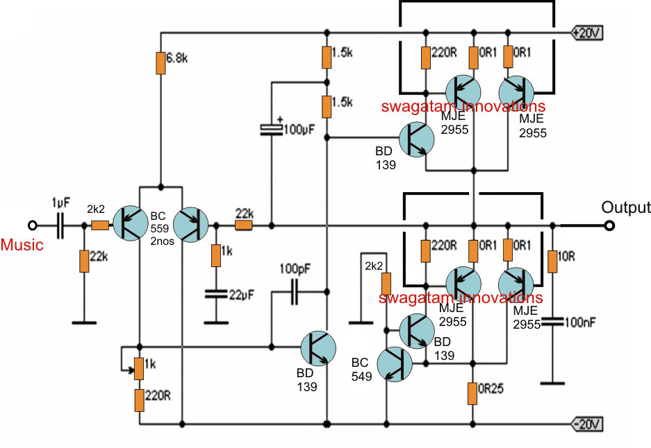
20W Class-A Amplifier Circuit
The sink shown here in the diagram is built on the similar concept to that of the output stages. 4x1ohm 1W resistors [0.25ohm] are placed in parallel. However, it may need some experimentation as the current gets determined by the base-emitter voltage BC549. The way the circuit works, BC549 will fetch base current that are in excess from the resistors. As the voltage exceeds to 0.65V across the resistors, the transistor starts and further adjusts balance. Furthermore, you can also set the DC offset using 1K trimpot to manage the LTP.
Optimum Current
Ideally the Class-A amplifier should maintain operating current 110% more than the peak current of the speaker. So a loudspeaker with an impedance of 8ohm and +/-22V supply of current, the maximum current of the speaker will be:
I = V/R = 22/8 = 2.75A.
The above calculation does not indicate the loss of current during output. It is definite that there will be loss of 3 volts in the output of the circuit, which is based on the loss in the emitter or driver resistors and the loss in output device.
The maximum voltage therefore is 2.375A @ 8ohms = 19V peak. Now by adding fudge factor to 110% the operating current is 2.6125A (2.6A approx.), and following this, the output power would be 22.5W.
However, it is important to note that whereas –ve supply is constant, the +ve on the other hand varies from the available steady current. With high signals the current gets doubled as the upper transistor turns on or for negative peaks it will go down to zero. This situation is a common occurrence on Class-A amplifier [single-ended] and it makes the power-supply design complex.
Adjust Quiescent Current
If the current sense resistor is more than optimal then you can use trimpot and wiper to the base of BC549 for accurate current flow. However, do keep in mind to maintain distance between the sense resistor from those that generate high source, for example, power resistors. Maintaining no safe distance will lead the current to drop with the amp getting hotter.
Be cautious when using the trimpot, since the wiper is wounded to supply line of -35V. A wrong move here may damage the trimpot. Therefore, initiate with the wiper at the collector of the output devices. Slowly increase the current till it reaches the required setting. You can also use multi-turn pot as an alternative, which would be the best.
The following diagram shows making of a current sink variable for the proposed 20 watt amplifier circuit.
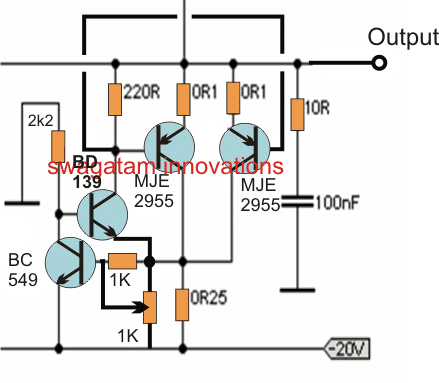
Variable Current Source
The use of 1K resistors as per figure is to ensure not to sink infinite current even when pot turns into an open circuit. Also it is necessary to give time [10 minutes or more at times] to stabilize the temperature across the heat-sink. However, the time to reach the operating temperature may vary based upon the size of the heat-sink, as bigger heat-sink comes with higher thermal mass and thus it takes time.
Heat-sink is one of the most vital components on a Class-A design. It is therefore mandatory to use a sink that would have thermal rating, which is less than 0.5°C/Watt. Consider a situation when the dissipation is about quiescent 110W, a heat-sink with the said specification will have 55°C rise in temperature, and the transistors on 80°C which eventually makes it hot. You can use thermal rating of 0.25°C, but there won’t be much effect on generated heat.
Another Simple 20 Watt Amplifier
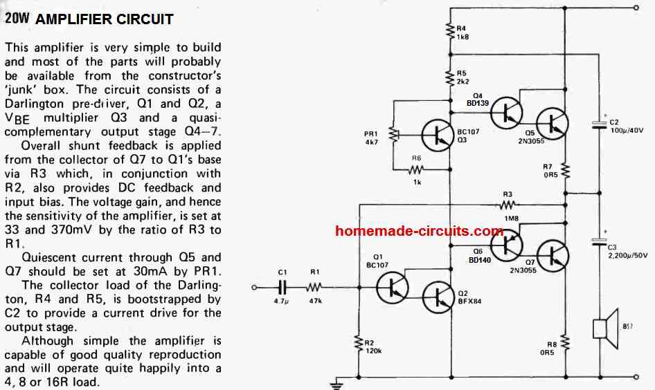
This 20 watt amplifier circuit is a snap to construct and the majority of of the components is going to be accessible from your 'junk' box. The design is made up of Darlington pre-diriver, Q1 and Q2, a VBE multiplier transistor Q3 and a quasi-complementary output stage comprising of transistors Q4-7.
All round shunt feedback loop is implemented through the Q7 collector to Q1's base by means of R3. this resistor R3 along with resistor R2, additionally offers DC feedback and input bias. The voltage gain, and therefore the amplifier's level of sensitivity, is defined at 33 and 370mV through the ratio of the resistive divider R3 to R1.
The quiescent current by means of transistors Q5 and Q7 must be adjusted on 30mA using the preset PR1. R4 and R5 form the collector load of the Darlington transistor, which is bootstrapped by the capacitor C2 in order to supply a current drive for the output stage.
Despite the fact that great simplicity, the 20 watt amplifier has the ability to generate a good quality audio reproduction and can work pretty well using 4, 8 or 16 ohm load.
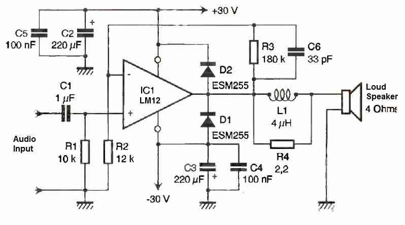
Using MOSFETs
The circuit presented in the following figure is for individuals who would want to experiment with a straightforward amplifier employing power MOSFETs in the output stage.
The design works with a simple setup that is very much like those designs that use a common emitter input transistor (Tr1) directly operating a common source MOSFET driver device (Tr2) that subsequently instantly drives the complementary common source output transistors (Tr3 and Tr4).
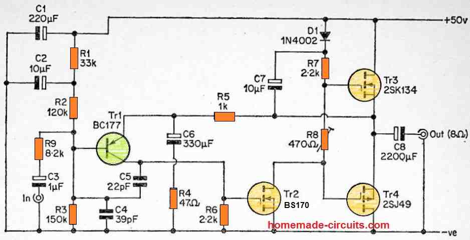
R5 delivers 100% negative feedback in the amplifier on DC to ensure that R1 to R3 enables you to bias the output with the suitable potential. C6 and R4 decouple the feedback to some extent at audio frequencies and deliver a voltage gain of approximately 20 times (26dB).
This allows the circuit an input sensitivity of roughly 625mV RMS into 70k for an output power of 20 watts RMS. R8 is employed to fix the most suitable quiescent current by means of the output transistors, which is around 80 to 100mA.
Power MOSFETs work in the negative coefficient mode, which means temperature compensation circuitry is never important for them. R9 and C4 is configured like a low pass filter at the input of the circuit, which facilitates eliminating issues of RF interference. C5 shifts the circuit a bit towards the high frequencies, assisting stability as well as serving to inhibit radio frequency vilnerability.
C3 and C8 are positioned as the input and output DC blocking capacitors respectively. Applying a 50 volt DC supply with a load of an 8 ohm speaker, this amplifier circuit is able to deliver an output power of 20 watts RMS effortlessly.
An output power of approximately 15 watts RMS could be accomplished through a loaded supply voltage of approximately 40 volts roughly, and around 30 watts RMS might be reached employing a 60 volt DC input with an 8 ohm loaded speaker.
Despite the fact that the circuit might not be eligible for the super Hi-Fi class by existing specifications, it can produce an amazing degree of overall performance for a model of this sort of straightforwardness (it does, in fact, solely works with 4 transistors)!
The overall harmonic distortion is usually effectively under 0.1% at nearly all output powers and frequencies, although it can increase somewhat at high and low output powers, and with high frequencies (as you could anticipate).
Although the BC177 transistor used for Tr1 is specified with a maximum emitter to collector voltage rating of only 45 volts, it really is protected to work with this device in this circuit using a supply of 50 V.
Using Darlington Transistor Pairs
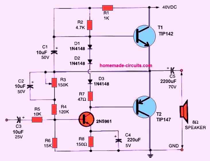
Two TO -220 monolithic Darlington transistors are used to create the audio output in the 20 watt push-pull amplifier circuit shown above.
A 20 watt output into an 8 ohm load requires an input signal of 1.2 volts. The source's input impedance is 10K ohms.
Preset R3 is used to adjust the quiescent current of the amplifier.


Questions & Answers
Question
What supply voltage is best for your circuit “Another simple 20 watt amplifier”
You can try 24V initially, and increase upto 30V.
Thank you but I’m already at 25v. Problem is distortion – Q1 bias is at .5v and I can’t seem to increase it by changing R2 and R3. I had to substitute Q2 (BZX84) for another, do you think it could be the issue? Quiescent current is ok at 30mA. Can you suggest anything?
I think Yes, the Q2 replacement can be the problem. Q1 and Q2 work like a Darlington pair, so if the new transistor has lower gain or different VBE then distortion can happen even if the idle current is 30mA. Also check the voltage at Q1 collector. It should be near half the supply, around 12 to 13V with 25V input. If it is not then check Q2, Q1, R4, R5 and all the solder joints around them. Also tell me which transistor you used instead of the BFX84. That will help to find the problem.
Ok, supply is now at 16.6v (dirty multimeter probes), still too high right?
Bias is low on output transistors AND Q1, what do think? Seems like something is open? Bias on Q3 is ok @ .6v ?
Yes, 16.6V is still a bit high. It should be near half the supply. If the bias is low on both Q1 and the output transistors, but Q3 has about 0.6V, then I also think something around the input/driver stage is not working properly. Check Q2 again, R4, R5, R6, and R3 for wrong value or open connection. Also check for a bad solder joint or PCB track. One open resistor or bad connection in that area can cause exactly this problem.
2N3019 is what I used as a replacement for Q2
That does not look like a close replacement for the BFX84, and its gain and VBE can be different. Since Q1 and Q2 work as a Darlington pair, that can cause distortion. If possible try using a higher gain transistor like BC337, 2N2222A, or another suitable high-gain small signal NPN, then check the Q1 collector voltage again. It should be close to half the supply voltage.
Sorry, I meant to say that the bias on Q1 NEVER gets above .5v no matter what.
Changed Q2 to 2n2222a. No significant change. Changed R2 value to 160k, voltage at Q1 collector is now 12v.
Experimented with changing other values but bias on Q2 NEVER gets above .5v, no matter what I do.
Output stage all under biased at .4 to .5 volts
OK…now the Q1 collector at 12V looks much better. That means the input stage is now biased about right. Since the output transistors are still only getting 0.4 to 0.5V, I would now look around Q3, PR1 and R6. The VBE multiplier should be able to adjust the voltage across the driver/output stage. If turning PR1 from one end to the other does not change the voltage much, then PR1, R6, Q3, or one of their connections may be open or wired wrong. Also check the pinout of Q3 carefully, because different BC107 versions can have different lead arrangements.
Also, please measure the voltage directly across the collector and emitter of Q3 while turning PR1. If that voltage does not vary (roughly from about 1.2 V to over 2 V) then the fault is almost certainly in the VBE multiplier itself.
hola me quiero hacer un amplificador de 15watts con tip142 y 147 con operacional ne5532 me podriaas ayudar gracias
Hey Jorge, sorry I do not have a ne5532 based amplifier design currently, if I find it will surely post it for you…
Hey I’m going to build the “Another Simple 20 Watt Amplifier” circuit.
I have a 19v laptop PSU I’ve successfully used on similar, simpler amps. Would that be suitable for this without any changes (R4/R5?).
Don’t mind the loss in power.
Also would you mount all 4 output transistors on a heat sink, or just Q5+Q7?
Yes, I think 19V should have no problems with the mentioned design, just make sure to adjust the PR1 quiescent current setting preset correctly. All those 4 BJTs will need to be mounted on heatsinks.
In the “Using Darlington Transistor Pairs” circuit there is a short circuit in the circuit of resistor R2 (C1-R2, or C1-R2, R1)
Sorry for the trouble, yes that’s a printing error. The link between C1 and D1 must be removed.
Hi Swagatam;
I had opened the same topic but now I have realized that then I made a mistake by disregarding the important point. So please let me ask again the same subject.
My TDA2030A amplifier circuit has 4 input / output points. 1- 12 V +/- input. 2- Speaker output. 3- PCB mount female audio connector input socket and
4- Entrance connector (2 pin PCB mount screw terminal)
12 V input, speaker output and audio input are all clear and no problem. But as to entrance terminal (above item 4) one pin of this is common with the ground and other pin is common with the one pin of the speaker output.
As a result I will try this TDA2030A circuit to connect to my PC USB output. And as you advised there will be no contact + pins of TDA2030 circuit and PC USB output. However grounds will be common.
The question is about above item 4. I am not able to understand about its function and need your opinion! Best Regards
Hi Suat,
The ground line or the ground pin will be common to all. It will be common to the amplifier input (entrance), output (speaker) and the USB ground.
The +5V of the USB must be left unconnected.
+12V must be fed to the amplifier positive line separately from a 12V power supply. The ground line of the power supply will be common to all as explained above.
The ground line is common so that the data signal from the USB can enter the amplifier and then pass to the common ground line to complete the circuit.
Hi Swagatam;
I appreciate your supports so far. My PC embedded sound car is off because of reverse overload voltage from mic input. Please advise if there is home made USB circuit is available instead of PC sound card. Thanks
Hi Suat, are you asking for a USB amplifier circuit. If yes, then you can probably try the following circuit:
https://www.homemade-circuits.com/usb-5v-amplifier-circuit-for-pc/
I am sorry but to my opinion this USB 5 v amplifier only use 5 v power supply thru PC that may be fine for phone and we can use it also in case our PC sound card is OK. I am not sure but I think it will be no remedy since my PC sound card is out of order. Please confirm and advice if I miss something.Regards
Actually, I am too not very sure if the above circuit can be replaced for a sound card, since I do not know much regarding how a sound card works.
Hi Swagatam;
I had made an amplifier circuit. Input voltage is 12 Volt. A soon later about 30 minutes there is no sound. And I hear a sound like whistle when I cut the input power. Then again it works as soon as input voltage is applied. Please share your opinion on the weird situation. Thanks
Hi Suat, it can be difficult to understand the fault without a careful practical checking of the circuit. However it seems one of the capacitors may be faulty.
Mau tanya pak. Apa skema ini mmg benar2 bekerja?
thank you sir..i am waiting for your post
sir,
can you pls give me a circuit of automatic water tap which operates when we show our hand..i need somewhat cheaper one.and easy to make ..i have the valves
NVD, I'll try to post it soon…