In this post I have explained a simple to build ultrasonic insect repellent circuit which can be installed in farms and used by the farmers for driving away all sorts of insects, bugs, grasshoppers etc in order to protect the crops from these potentially harmful pests. The idea was requested by Mr. Cia Brisat.
Technical Specifications
I am a farmer, and need a simple repelling device for use in agricultural equipment, so i can reduces insecticide use.
device features;
a. solar powered with rechargeable battery.
b. a multi pulse repeller, keeps changing the ultrasonic pulse it emits. prevent pests from getting used to the sound.
c. effective range: up to 5000sf.
d. ultrasonic frequency: from 13.5khz to 95khz.
e. dual speaker or more.
could you please help me with a circuit diagram?
thank you.
cia brisat
The Design
The proposed solar insect repellent is based on an ultrasonic wave generator circuit which works by influencing the normal behavior of insects, ultimately driving them away from the area.
The device functions by generating a high frequency at ultrasonic level (above 20kHz), with short pulses. The frequency of the pulses range from 5kHz to 40kHz, selected randomly and transmitted in the environment through special piezo transducers or high power tweeter speakers.
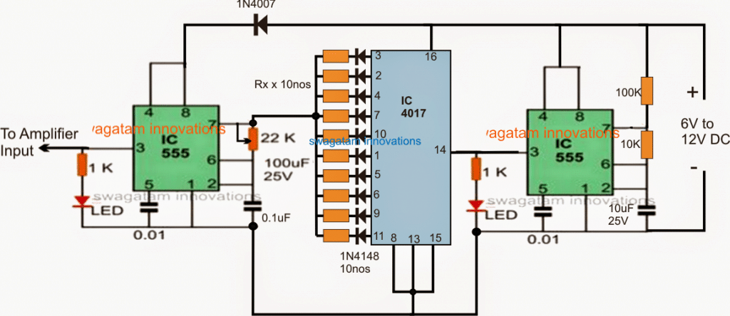
Referring to the above diagram, the design depicts an ultrasonic frequency generator circuit which features a random frequency selector stage. The idea may be understood with the help of the following explanation:
The IC 555 stages on the left and on the right side are both configured as astable multivibrators for generating the respective frequencies across their output pin#3.
How the IC 555 Operates
The left side IC 555 actually generates the ultrasonic pulses whose frequency is determined by the instantaneous high available across one of the associated sequencing pinouts of the IC 4017.
The shifting or sequencing high logic produced across the 10 outputs of the IC 4017 connects the particular resistor in the array such that this resistor allows the calculated amount of voltage to pin#7 of the IC, and becomes responsible for determining a particular ultrasonic frequency for the left IC 555 stage.
The 10 resistors across the 4017 IC outputs can be selected with some trial and error. For example these 10 resistors may be selected as 4K7, 10K, 15K, 22K, 33K, 39K, 47K, 68K, 82K, 100K. You can try other values also for getting other desired ultrasonic frequencies across the output of the left side IC 555.
Why IC 4017 is Used
This enables the production of a randomly changing ultrasonic output at the pin#3 of the left IC 555. These randomly changing frequency ranges can be appropriately fixed by assigning calculated resistors across the indicated outputs of the IC 4017.
The speed at which the random selection is implemented depends on the frequency of the clocks applied at pin#14 of the IC 4017 via the right side IC 555 astable stage.
This speed can be altered by either changing the pin#7 upper resistor or the value of the 10uF capacitor of the right IC 555.
The 22k pot associated with the left IC 555 is used for adjusting the pulse width of the ultrasonic waves, the best response may be achieved by some experimentation and by some trial and error.
Since the generated ultrasonic waves needs to powerful enough to reach the entire field, the emission impact needs to be extremely powerful.
This is ensured by feeding the pin#3 output from the left IC 555 to the input of a 100 watt amplifier. This amplifier may be built at home by using a suitable circuit design such as a TDA7294 IC or by procuring a readymade unit from the market.
Once all the above procedures are executed, a high power transducer or a tweeter may be connected with the output of the amplifier for initiating the intended ultrasonic insect repelling actions.
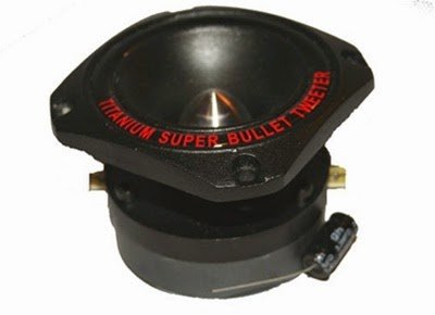
An example of a 100 watt tweeter can be witnessed in the following image:
Power Supply Specs for the Circuit
The circuit is specified to work with any voltage within 6 to 15V, therefore a 12V battery becomes just sufficient for powering the entire unit, although for delivering 100 watts, the AH rating of the battery will need to be at least 50 AH.
In order to make the circuit independent of an external power source, a solar panel may be incorporated for charging the specified battery at an optimal rate which could be around 10amps for a 50 AH lead acid battery.
This implies that the solar panel must be rated to produce 20amps at 15V in order to charge the battery, as well as enable the circuit to be driven in the day time while the battery is also being charged simultaneously.
Using a 10 Amp Battery Charger
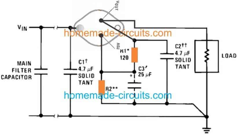
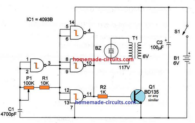
A suitable 10 amp solar battery charger circuit for keeping the battery optimally charged may be seen in the following diagram and used accordingly:

Questions & Answers
Hello, I want to add solar as its power and fuse for safety, can you give me some suggestions? Also, can I use lower watt for amp? Thank you so much
Hi, yes you can add a solar panel. The solar panel can be rated at 15V, 1 amp. You can use a low power amp, but lower power amp would mean a low operating range for the ultrasonic waves.
How can the volume be reduced?
Vishwanath, volume can be reduced by connecting a potentiometer at the output of the left IC 555. potentiometer outer terminals will connect between pin#3 and ground, the wiper arm will connect with the amplifier input pin. The circuit ground and the amplifier ground should be also connected in common.
Sr I have added a 100w amplifier to this circuit, how can I increase the volume?
Dear Sir, the diagram mentions a capacitor of 100uF, 25V at the second 555, but does not depict such a capacitor and where it should be inserted.
Could you please elaborate on this.
Also could the 10K resistor at the first 555 be replaced with a higher resistance pot to vary the Hertz output?
Many thanks.
Hi Hans, sorry, it is actually a printing mistake. You can simply ignore the 100uF/25V shown in the diagram.
The output frequency is actually determined by the values of the 10 resistors connected across the ouputs of the IC 4017. The right side IC 555 frequency decides how fast or slow these 10 frequency ranges could be sequenced or shifted to produce 10 different ultrasonic frequencies at pin#3 of the left side IC 555. The speed at which the 10 ultrasonic frequency ranges can be sequenced can be altered by adjusting the 100K resistors of the right side IC 555. You can replace the 100K resistor with a 100K pot but make sure to connect a 10K resistor in series with this 100K pot.
Good afternoon. I would like to understand whether it is possible to use this device to repel mosquitoes from a person, for example, while fishing. Can I use a lower power amplifier like 2-5 watts?
Yes, it should be able to repel mosquitos even outdoors, but since I have not tested the response practically, I cannot guarantee the results.
Hello Sir,
I’m a college student.Our design project is to make solar ultrasonic pest repellent with variable frequency changing,also a fluorescent lamp attached to the device.Can u please share me the block diagram,working and components used.Tomorrow is the last date to submit PPT…:)
Hello Agnus, the complete schematic is already given in the above article.
For the fluorescent driver you can try this simple idea:
https://www.homemade-circuits.com/simple-20-watt-tube-emergency-light/
Hai sir….
Pls tell the value of RX
10resistors value
Hi Kesav, the values will need to be experimented with.
initially you can bewteen 10K to 100K uniformly distributed values for the 10 resistors, and check the response, and later on change the values to archived higher accuracy
Dear Swagatam,
I am working on a project ultrasonic plastic welding, which requires 15htz/20htz/40htz and 1500W – 2000W power. Is it possible to use this circuit with ready made 2000w amplifier. Then I need fixed frequency and continuous pulse. what modification should be done to avoid randomly changing frequency. Or can I use the simple mosquito repellent circuit.
Thanks.
Dear Vijayan, for a reliable functioning an IC 4060 based oscillator would be a better option
you can try the basic design shown below
https://www.homemade-circuits.com/2011/12/how-to-understand-ic-4060-pin-outs.html
Dear Mr.Swagatam.
Could you please recommend me the amplifier circuit which can be support those frequencies ?,thanks in advanced, best regards, Ronald.
Dear Ronald, you can try any amplifier circuit rated at 100 watts, you can search it online, or perhaps try the following:
https://www.homemade-circuits.com/2012/04/how-to-make-simplest-100-watt-mosfet.html
Dear Swagatam
Your circuit is a good design however, I am sorry the idea does not work.
I have tested it long ago, bringing the output very close (1") to mosquitoes.
Please see this article.
Dear Abu-Hafss,
I just designed what the user wanted and as per his instructions, may be the person who requested the circuit was confident about the concept….not sure?
By the way it's intended for bigger pest like grasshoppers, moths, butterflies, rodents, bats….
it might require a few days of practical testing and monitoring to confirm the results