Connecting transistors in parallel is a process in which the identical pinouts of two or more transistors are connected together in a circuit in order to multiply the power handling capacity of the combined parallel transistor set.
In this post I have explained how to safely connect multiple transistors in parallel, these can be BJTs or mosfets, I will elucidate both.
Why Parallel Transistor become Necessary
While making power electronic circuits, configuring the power output stage correctly becomes very crucial. This involves creating a power stage that can handle high power with least effort. This usually is not possible using single transistors, and requires many of them to be connected in parallel.
These stages primarily may consist of power devices like the power BJTs or MOSFETs. Normally, single BJTs become sufficient for getting moderate output current, however when higher output current is required, it becomes necessary to add more number of these devices together. Therefore it becomes necessary to connect theses devices in parallel. Though using single BJTs is relatively easier, connecting them in parallel needs some attention due to the one significant drawback with transistor characteristics.
What is "Thermal Runaway" in BJTs
As per their specs, transistors (BJTs) need to be operated under reasonably cooler conditions, so that their power dissipation does not exceed the maximum specified value. And that's why we install heatsinks on them to maintain the above criterion.
Moreover, BJTs have a negative temperature coefficient characteristic which force them to increase their rate of conduction proportionately as their case temperature increases.
As its case temperature tends to increase, the current through the transistor also increases, which forces the device to heat up further.
The process gets into a kind of chain reaction heating the device rapidly until the device becomes too hot to sustain and gets permanently damaged. This situation is called thermal runaway, in transistors.
When two or more transistors are connected in parallel, due to their slightly differing individual characteristics (hFE), the transistors in the group may dissipate at different rates, some a little faster and others a little slower.
Consequently, the transistor which may be conducting slightly more current through it might start getting heated up faster than the neighboring devices, and soon we may find the device entering into a thermal runaway situation damaging itself and subsequently transferring the phenomenon to the remaining devices as well, in the process.
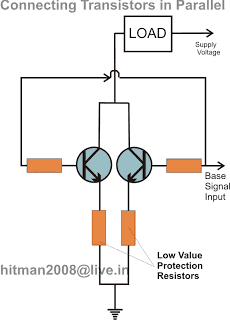
The situation can be effectively tackled by adding a small value resistor in series with the emitter of each transistor connected in parallel. The resistor inhibits and controls the amount of current passing through the transistors and never allows it to go to dangerous levels.
The value should be appropriately calculated, as per the magnitude of the current passing through them.
How to connect Bipolar Transistor in parallel
The following circuit diagram shows how to correctly connect two or more transistors in parallel. The emitter resistors make sure that the current sharing across the transistors is uniform and thus a thermal runaway situation is avoided.
How to Calculate the Emitter Current Limiting Resistor in Parallel BJTs
It is actually very simple, and could be calculated using Ohm's Law:
R = V/I,
Where V is the supply voltage used in the circuit, and "I" could be 70% of the transistor's maximum current handling capacity.
For example let's say if you used 2N3055 for the BJT, since the max current handling capacity of the device is around 15 amps, 70% of this would be around 10.5 A.
Therefore, assuming the V= 12V, then
R = 12/10.5 = 1.14 Ohms
Calculating the Base Resistor
This can be done using the following formula
Rb = (12 - 0.7)hFE / Collector Current (Ic)
Let's assuming hFE = 50, Load current = 3 amps, the above formula could be solved as under:
Rb = 11.3 x 50 / 3 = 188 Ohms
Considerations
To calculate the parameters safely we must take care of the following considerations:
Current Sharing with Emitter Resistors:
- The voltage drop across each emitter resistor is supposed to be approximately equal.
- The value of the emitter resistors can be calculated with regards to the desired current and the voltage drop across them.
Thermal Considerations:
Power Dissipation: Calculate the power dissipation of each transistor using the formula:
P = VCE * IC
Junction Temperature: Estimate the junction temperature using the thermal resistance of the transistor and the heat sink:
Tj = Ta + (Pd * θJA)
- where:
- Tj: Junction temperature
- Ta: Ambient temperature
- Pd: Power dissipation
- θJA: Junction-to-ambient thermal resistance
How to Avoid Emitter Resistors in Parallel BJTs
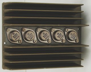
Although the use of emitter current limiter resistors looks good and technically correct, a simpler and a smarter approach could be to mount the BJTs over a common heatsink with a lot of heatsink paste applied to their contact surfaces.
This idea will allow you to get rid of the messy wire-wound emitter resistors.
Mounting over a common heatsink will ensure quick and uniform sharing of heat and eliminating the dreaded thermal runaway situation.
Moreover since the collectors of the transistors are supposed to be in parallel and joined with each other, the use of mica isolators no longer become essential and makes things much convenient as the body of the transistors get connected in parallel through their heatsink metal itself.
It's like a win-win situation...transistors easily combining in parallel through the heatsink metal, getting rid of the bulky emitter resistors, a well as eliminating the thermal runaway situation.
Connecting MOSFETs in Parallel
In the above section I have explained how to safely connect BJTs in parallel, when it comes to mosfets the conditions become entirely the opposite, and much in favor of these devices.
Unlike the BJTs, mosfets do not have the negative temperature coefficient problems, and therefore are free from the thermal runaway situations due to overheating.
On the contrary, these devices exhibit a positive temperature coefficient characteristics, meaning the devices begin conducting less efficiently and begin blocking current as it begins getting warmer.
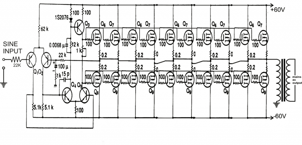
Therefore while connecting mosfets in parallel we do not have to worry much about anything, and you may simply go ahead hooking them up in parallel, without depending on any current limiting resistors, as shown below. However using separate gate resistors for each of the mosfets should be considered....although this is not too critical..
Important Considerations for MOSFETs
For connecting MOSFETs in parallel we must consider the following parameters for increased safety and higher efficiency from the devices:
Power Dissipation:
P = Vds * Id
- where:
- P: Power dissipation (Watts)
- Vds: Drain-source voltage (Volts)
- Id: Drain current (Amps)
MOSFET Parameters:
On-Resistance (Rds(on)): The combined on-resistance of parallel MOSFETs is:
Rds(on)total = Rds(on)individual / N
- where:
- N: Number of parallel MOSFETs
Gate Charge (Qg): The total gate charge can be found by adding the sum of the individual gate charges:
Qg(total) = N * Qg(individual)
Conclusion
In the above post we elaborately learned how to connect transistors in parallel. We can summarize the procedure as I have explained below:
When bipolar transistors are connected in parallel, always make sure to add a calculated emitter resistor for each transistor. This resistor enables the BJTs to share the load current and thermal dissipation uniformly, which solves the thermal runaway problem in BJTs
If you want to avoid the emitter resistors, you can consider mounting the transistors closely, over a single common heatsink, so that the heat dissipation is shared uniformly and a thermal runaway situation is avoided.
For MOSFETs no source resistors are required because MOSFETs are negative coefficient transistors and a thermal runaway situation is not applicable to these devices.
However still, to ensure high efficiency from the parallel MOSFETs it is recommended to mount them over an adequately rated heatsink.



Questions & Answers
swagatam sir i am free lance electronic hobbyist too. I want to know from scratch of basic electronics to build a strong foundation for my knowledge purpose.please suggest some books or upload some tutorial so that i can learn from you .
Hi Kathiravan,
I am myself planning to write a related book and sell the publication at cheap rates for the hobbyists here, presently there's no such info online which would enable a new hobbyist to grasp the facts quickly within 6 months or so, if i find any will let you know for sure.
yes, but why would you require parallel transistors for a relay??
Hi!
The piece of information I cannot find anywhere is what the specs should be for the emitter resistor (that is resistance and max amperage).
In my project I have two screwdrivers with controller, transistor and motor. I want to let one controller switch both transistors, put them in parallell and so regulate both motors from one potentiometer.
I don't have the specs for the transistors, but know of course that they can handle full load from one motor each. The motors operates on 18 V and drops at max load to 15,6 V/18Amps.
What specs should my emitter resistors have, and how does one dimension such in the general case. I cannot find this answere anywhere, and I highly suspect that i e electric car situations would require something rather different from low voltage/power circuit boards?
Thanks!
Hi, In general the resistors must be rated such that even with a short circuit condition the resistors are able to restrict the current from exceeding the BJTs breakdown limit.
for example if the breakdown limit of a tramsistor is 15Amp, we can consider 14 amp as the safe limit and then use Ohms law for dimesnsionng the resistor as given below, ….assuming 12V as the supply voltage:
R = 12/14 = 0.85 ohms
Hello Hitman,
Even by your standards this is an awesome post, particularly the idea of preventing thermal runaway by sharing heat sinks. I'm actually revisiting your solar tracker circuit and needed more power, so here i am. Keep up the good work,
Brian
Thanks very much Brian, I am glad you liked the post!!
I always thought that BJT’S had a POSITIVE Temp Coefficient and MOSFETS had a NEGATIVE Temp Coefficient.
Please how can I combine two pnp and two npn transistors together in parallel
that’s not possible, you cannot connect NPN and PNP in parallel
Hello sir… I want to know that how to connect the two npn bipolar transistor for my power supply.. Because when i connect one transistor then it is blow out… Please suggest me how to connect it… I used following components in my power supply lm317, bd139, 6a04 diode, 12-0-12 8amp transformer and 2n3055 transistor
Apurva, please show me the circuit or the link which you are referring to!
How to send the image in this comment box image file not be send
send me in facebook
Hello sir i would send the cricuit digram into ur facebook id sir…
send it here:
https://www.facebook.com/swagatam.majumdar.7
Good day,
I am new to electronics.
Digikey had an article on connecting NPN transistors in parallel – to avoid thermal runaway. (TIP41C)
I gained a lot of insight from your article.
From the diagram you have in your article I can see an orange box (resistor), connected to the base.
How do we measure this base resistor, if at all it is needed.
What wattage should be the resistors (emitter and/or base )
Thank you Christopher, Glad you liked my site!
I have updated the info in the article please check it out.
Wattage of the emitter resistor will be V x I, 12 x 10 = 120 watts, that looks too big, but if the load current is at full 10 amps then it will be this big….
Thank u so much let me try out those ideas ,becoz was stranded with rhat problem of thermo heating of bjts
Glad it helped Mubiru, thanks for your feedback!
Thanks for the article. I’m designing a constant current circuit for a power supply and was actually thinking of using 2n3055 transistors. I want it to be able to handle at least 25 amps or more, so thought about 2 or even more in parallel. Your article answered my question. I know that I could probably use a single mosfets, but have a good supply of 2n3055s. Can make them very easy to replace if needed also.
Thanks again,
Ken
Thank you for liking the post, yes you can certainly try that!
Thanks very much !
I am trying to make an ultrasound transducer cleaner circuit which requires 200 watts. I keep trying to wire transistors together and it damages it. What can I do?
Can you please specify how much base voltage, collector voltage and collector load current you are using for the transistor? I will try to help!
base voltage: 5 volts (tried up to 10 volts)
collector voltage: i am using a variac set to 5 volts (tried up to 10 and 20)
collector current with no load: 3 – 7 amps with load 500 milliamps.
I am using 2N3055(NPN).
I tried to use two transistors in parallel but the current went up from 3 amps to only 4.5 amps. I wired 7 more in parallel and for some reason the current became less than the first time about 1.5 amps
Also, this is the setup:
a variac rated at 2000 watts is connected to a transistor and it passes through the lower voltage side of a transformer and back to the variac. That creates a current on the other side of the transformer with 10 times the voltage, so 5 volts becomes 50 volts, and i am connecting the two ends of the transformer to the two ends of the transducer. It is a 100 watt transducer I got on amazon. As for the base current of the transistor, I have a signal generator which either wire directly to the base of the main transistor, or, in order to amplify the base current, use a variable dc supply set to 5 volts.
It runs fine with this setup. This is not the issue. The issue is that when I try to increase the variac voltage to 10 or 15 volts and then turn it on, the transistors get damaged and so I have to find a way to increase the total power while keeping the transistors intact. As I said, I already tried wiring several transistors in parallel and still it is at the same current
For a 500mA load a single 2n3055 should be just enough. Parallel connections may not be required. However to increase the gain you can try converting the 2N3055 into a Darlington configuration, by adding another 2N2222 transistor with it, as shown in the following diagram:
Ok. But i am trying to say that only 500ma are coming through. At 5v that is 2.5 watts. But I need around 200 watts for my ultrasound cleaner. Can you help me increase the power? Even when I wire the transistors in parallel it gives around the same amount of current as with one transistor. Why is that?
OK, sorry for the confusion. So you have 5V for the base drive, 50V 200 watts 4 amp for the collector load.
With 50V 4 amps you can easily use a single 2N3055 with 2N2222 in the Darlington configuration, using 5V 1 amp at the base. You can replace the 2N3055 with TIP35 for better performance. You will need a heatsink on the transistors.
Let me know if you have more doubts.
I think I need a current of 40 amps total at 5v to be transformed to 50 volts at 4 amps to power the transducer. Or something along those lines
But you said you are converting 5V to 50V through a transformer?
Do you have a 50V source for the transducer, or not??
Yes I have a variable power supply that can do 50v. If I want to increase the wattage from 50v at probably 1A = 50W to say 300W what can I do? It needs to be at a very high power in order to work. A few hundred watts. The messaging comes a little out of order. I am not sure if I can use the DC power supply as a power source since it might be too low of power for this. So that is why I bought a 2000W variac as a power source. So I need to know 1) how to increase the power in general and 2) about using an AC variac for this. For some reason once I increase the power on the variac beyond 10V the transistor starts to conduct current. This does not happen on AC. Why is that? I appreciate your help.
Can you tell me what to do with regards to these issues?
The power consumption is determined by the load. The load decides how much power it wants to take. If the load is 300 watt then it will consume 300 watts, provided the source is able to supply 300 watts.
However, a transistor can never handle an AC load, it is designed to work with DC loads. So you will have to convert the 50V AC to 50 DC for powering the load. If your load is an AC load then transistor cannot be used, you will have to use a triac instead.
Also, do you know anywhere I can learn more about powering an ultrasound cleaner? Or a cheap amplifier I can buy? Maybe you can make it and I will buy it from you.
Sorry, I do not have sufficient knowledge about ultrasound cleaners so it can be difficult for me to assist you in this regard
Furthermore, I tried using a heatsink to pass 50v through the power transistors and after 1/3 of a second the transistor burned out and stopped working. This happened several times. So I need a way to divide the power among a few transistors. Or, use a lower voltage and get more amperage.
Transistor cannot be used for AC supply and AC loads, it will keep burning. You will have to use a triac instead for an AC load/supply
I rectified the AC Power through a power diode and led that to the transistors. I know how to connect one transistor without it burning, but how do I increase the power, because one transistor cannot tolerate the whole load. So do I connect them in parallel?
My idea is to connect them in parallel and add resistors, then increase the voltage so that the individual transistors have the same wattage through them (due to the resistor power drop) and since they are in parallel they will be adding together as parallel resistances, then lead that to the load. Is that a good idea?
You can add 2N3055 in parallel with a low value resistor in series with the emitters of each transistor, and mount them over a common single heatsink close to each other. But the problem is that each 2N3055 will require at least 25 to 35 mA base current. How will you supply this base current to each transistor? The solution is to replace the 2N3055 with a Darlington transistor such as TIP142. You can then connect 10nos of TIP142 in parallel with a series emitter resistor for each transistor. The resistor can be a 0.22 ohm 2 watt resistor
Thanks. Is it correct that the TIP142 is not a mosfet but is a BJT? Because I was having trouble connecting mosfets. I wire them the same way I wire a BJT with the common emitter configuration and it starts to conduct from the source to the drain without any gate signal applied? Do you know why that is happening?
TIP142 is a BJT not a mosfet. MOSFETs will not work properly with 5V gate supply. Without seeing your connection diagram it can be difficult for me to understand and troubleshoot your circuit.
https://1drv.ms/u/s!Ajs8vtOrFCHDjhwXmIAa4Y5s1iVO?e=HbueLt
That is the onedrive link for the picture of the circuit. What I mean to say is that just by connecting a battery across the source and drain, it conducts, without any signal on the gate. That is as opposed to the second picture where I show how I would expect it to work, with the battery connected on the gate.
I have IRFZ44N MOSFET’s and it does not matter whether the drain or source are positive or negative, it just conducts without a gate signal. I do not think it is a depletion type mosfet, but even if it is, with a signal at the gate it still conducts.
First of all you should never connect the supply voltage directly across the drain/source. You must always have an appropriately rated load in series with the supply, otherwise the mosfet could burn.
The gate of the mosfet should never be kept floating. For any mosfet always make sure to have a resistor connected across gate/source, then the mosfet will remain switched OFF by default.
Try adding a 1K resistor across the gate/source and check the response….and make sure you have a load in series with the drain supply.
https://1drv.ms/u/s!Ajs8vtOrFCHDjh1OzDwdZQOvhFl4?e=OaTggA
That is my circuit. You said I can add 0.22 ohm resistors in parallel with the emitters of each transistor. Is that what you mean as in my circuit?
As I said I am trying to increase the total power. I used 1 ohm resistors at the emitters and also 10 ohm. Is this circuit right?
Your circuit is not correct. For high current load you must use a Darlington for each transistor and then add them in parallel as shown in the following diagram:
How did you come up with a 0.22 ohm resistor? And why do they have to be individual darlingtons?
Actually 0.22 is incorrect, it should be 5 ohms since the input voltage is 50 V. We want restrict the max current per transistor to less than 10 amps
Using Ohms law R = V/I = 50 / 10 = 5 ohm
Using Darlington for each transistor is more efficient than using a single transistor for all the 2N3055
Hey, I have a maximum base voltage of 3.3V and a max base current available of 15mA (Raspberry pi pico).
I need to power a motor that requires about 3.7A. That’s the maximum it requires lol. It’s a 1ohm motor so I apply a voltage of 3.7V. Which transistors should I use and in what config. Thanks a lot!
You can use a Darlington transistor built using a 2N2222 and a 2N3055 transistors. The base resistor can be a 1K resistor. Let me know if you have any more doubts.
Ayee thanks a lot. I tried using what you suggested and it worked wonderfully!!! Though, I found a high hFE transistor – TIP122 – in my city somehow lol. Is there a benefit to using your suggested darlington config, or should I stick to the single BJT TIP122?
Glad it is working for you.
TIP122 will work but it can become extremely hot at 3 amp current that is why I suggested the 2N2222/2N3055 combination.
If i should connect two or more transistors is it the collector-emeter current that will increase or it is the watt that will be increased?
Current and wattage both will increase.
Can I connect 10 D2012 transistors in parallel, 5 together and the other 5 together and run it with 12volt?
You can connect them in parallel, however make sure to add a low value emitter resistor in series with each of the transistors as explained in the article, or alternatively, you can mount all the transistors over a common heatsink and very close to each other.
Or you can do both for optimal performance.
Hello sir,
I am a hobbyist, and have assembled a 6 phtodiode circuit. I have used Darlington pair [BC547 BJT NPN] for amplification of current. However, the measuremnts are not steady and stable. Can I add another Darlington pair or do I need to add a capacitor in photodiode circuit? I checked on multimeter, sometimes it reads 800 nF or mF [unable to measure].
Please revert.
Regards,
Sanjay
Hello Sanjay,
A single Darlington should be enough to amplify a signal from photodiodes, no need of adding additional Darlington BJTs, it won’t help.
Please let me know what you are try to build with the photodiodes?
Is it a proximity sensor?…if possible please show the schematic diagram, I will try to solve it for you.
Hello Swagatam
I am now 74 years old, so it has been many years since I studied at a technical academy. (and many years of developing electronic circuits)
Has there since been a change in how voltages are named in a schematic when we talk about voltage that occurs in an electrical circuit?
I have learned:
U = R*I
The value of U is denoted V (Volt)
The value of R is denoted Ohm
The value of I is denoted A (Amp)
So:
U(supply) is 12V
Not V(supply) is 12V
Is it legal today to mix the terms and values as you wish?
Is it me who hasn’t kept up with the times?
Regards Tommy.
Thank you Tommy, for the insights!
What you are saying is partially correct, however it is completely legal and legit to use the term “V” instead of “U”
If you search for “Ohm’s law triangle”, you will find that V is always used for denoting voltage.
I think “U” is more prevalent in the European countries, while “V” is a common worldwide notation for expressing Voltage.
However, it might not be appropriate to mix the terms in a schematic, if you are using “V” then you must stick with “V” and not mix the terms U and V.
Hello!
is it possible to take an output MOSFET or even a bipolar transistor
that is used for the final amplifier of a CB radio and place another transistor in Parallel. From what I have read, I would use a separate heat sink so that they are sharing the same heat sink together. Also I would connect them in a way so that the leads are actually the same length. With this set up, will it give better protection for any future over loaded current if you will, verses a single transistor or MOSFET? Thank you.
Hey, thanks for the comment, however I will need to see the schematic of the CB radio, without which it can be difficult for me to give any suggestions…