In this article I have explained a dual input hybrid solar and wind battery charger circuit using cheap and ordinary components.
The idea was requested by one of the interested members of this blog.
Technical Specifications
Good after noon sir am designing a " Solar and Wind energy harvest regulator circuit" which has two inputs and one output.
The PV solar panel ( 0-21V DC) and the other input is a wind turbine (15V DC).
The circuit must be designed for charging a 12v battery . the output current being delivered to the loaded battery must not deliver more than 3.5A.
My group and myself have gotten a few circuits off the internet and simulated them using pspice none of them is giving us the output current of 3.5 A. please sir can you please help us with examples of circuits which we can use.
The Design
In one of my previous posts I introduced a similar concept which enabled a battery to be charged from two sources of energy such as wind and solar simultaneously and without the need of any manual intervention.
The above design is based on PWM concept and therefore could be a bit complex and difficult to optimize for a layman or a new hobbyist.
The circuit presented here offers exactly the same features, that is, it enables the charging of a battery from two different sources, yet keeping the design extremely simple, efficient, cheap and hassle free.
So I have explained the circuit in details with the help of the following explanation:
Circuit Diagram
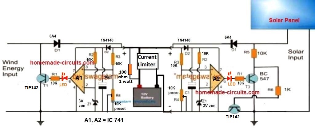
The figure above shows the proposed solar, wind twin hybrid battery charger circuit, using very ordinary components such as opamps and transistors.
We can see two exactly similar opamp stages being employed, one on the left side of the battery and the other on the right side of the battery.
The left side opamp stage becomes responsible for accepting and regulating the wind energy source while the right side opamp stage processes the solar electricity for charging the single common battery in the middle.
Although the two stages look similar, the modes of regulation are different. The wind energy controller circuit regulates the wind energy by shunting or shorting the excess energy to ground, while the solar processor stage does the same but by cutting of the excess energy instead of shunting.
The above explained two modes are crucial since in wind generators which are essentially alternators require the excess energy to be shunted, and not cut off, so that the coil inside can be safeguarded from over current, which also keeps the speed of the alternator at a controlled rate.
This implies that the concept can be also implemented in ELC applications also.
How the opamp is Configured to Function
Now let's investigate the functioning of the opamp stages through the following points:
The opamps are configured as comparators where the pin#3 (non-inverting input) is used as the sensing input and pin#2 (inverting input) as the reference input.
The resistors R3/R4 are selected such that at the required battery charging voltage, pin#3 just becomes higher than pin#2 reference level.
Therefore when the wind energy is applied to the left circuit, the opamp tracks the voltage and as soon as it tries to exceed the set threshold voltage, pin#6 of the IC goes high which in turn switches ON the transistor T1.
T1 instantly short circuits the excess energy restricting the voltage to the battery at the desired safe limit. This process goes on continuously ensuring the required voltage regulation across the battery terminals.
The opamp stage at the solar panel side also implements the same function however here the introduction of T2 makes sure that whenever the solar energy is higher than the set threshold, T2 keeps on cutting it OFF, thereby regulating the supply to the battery at the specified rate, which safeguards the battery as well as the panel from unusual inefficient situations.
R4 on both the sides may be replaced with a preset for facilitating easy setting up of the threshold battery charging level.
Current Control Stage
As per the request, the current to the battery must not exceed 3.5 Amps. To regulate this a standalone current limiter can be seen attached with the battery negative.
However the design shown below can be used with up to 10 amp current, and for charging up to 100 Ah battery
This design can be built using the following circuit:
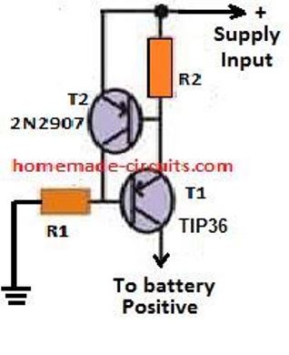
R2 may be calculated with the following formula:
- R2 = 0.7 / charging current
- wattage of the resistor = 0.7 x charging current
Parts list for the solar wind dual hybrid battery charger circuit
- R1, R2, R3, R5, R6 = 10k
- Z1, Z2 = 3V or 4.7V , 1/2 watt zener diode
- C1 = 100uF/25V
- T1, T2 = TIP142,
- T3 = BC547
- D2 = 1N4007
- Red LEDs = 2nos
- D1 = 10 amp rectifier diode or Schottky diode
- Opamps = LM358 or any similar
Simplified Solar, Windmill Hybrid Battery Charger Circuit
A very effective solar, and windmill combined hybrid battery charger can be built using just a couple of transistors, as shown in the following image:
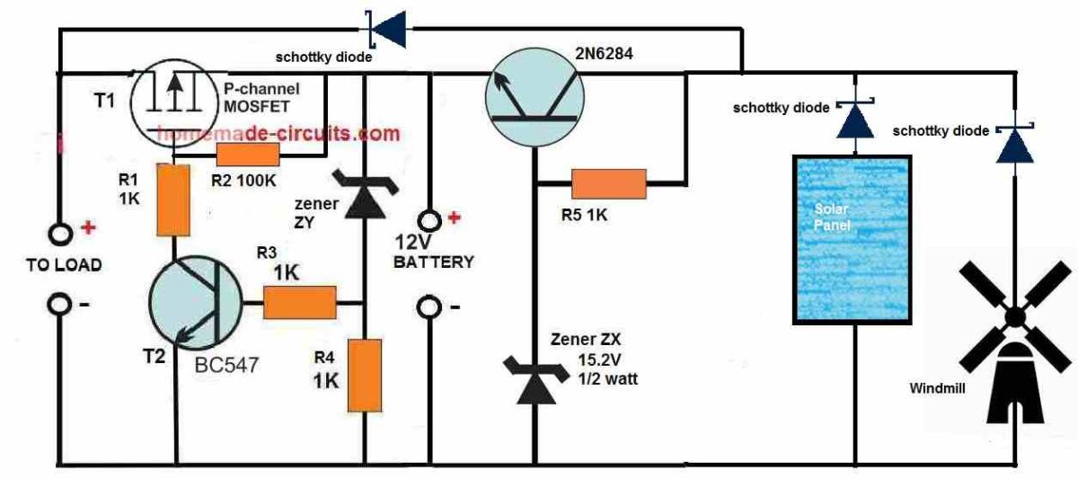
This is actually a simple yet very effective, full fledged hybrid charging system which will not only combine the solar and windmill power to charge your battery faster, but also make sure that the battery is never over charged or over discharged. That means, your battery condition will be always maintained efficiently ensuring a longer battery life.
Another great feature of this hybrid charger is that, the load can be operated simultaneously while the battery is being charged, without loading the battery.
Also, in case the solar/wind power is unavailable and the battery reaches lower discharge level, the load will be automatically cut off, to prevent over discharging of the battery.
Double DC Input Hybrid Charger Circuit
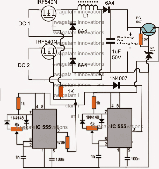
A similar second hybrid design below describes a simple idea which enables the processing of two different sources of DC inputs derived from different renewable sources.
This hybrid renewable energy processing circuit also includes a boost converter stage which effectively raises the voltage for the required output operations such as a charging a battery. The idea was requested by one of the interested readers of this blog.
Technical Specifications
Hi, I am a final year engineering student, i need to implement a multi input chopper (integrated buck/buck boost converter) for combining two dc sources(hybrid).
I have the basic circuit model, can you help me to design inductor, capacitor values and control circuit for the chopper. I have emailed you the circuit design.
Circuit Operation.
As shown in the figure the IC555 sections are two identical PWM circuits positioned for feeding the adjoining double input boost converter circuit.
Following functions take place when the shown configuration is switched ON:
DC1 may be assumed as the high DC source such as from a solar panel.
DC2 may be assumed as alow DC input source, such as from a wind turbine generator.
Assuming these sources to be switched ON, the respective mosfets start conducting these supply voltages across the following diode/inductor/capacitance circuit in response to the gate PWMs.
Now since the PWMs from the two stages might beset with different PWM rates, the switching response will also differ depending upon the above rates.
For the instant when both the mosfets receive positive pulse, both the inputs are dumped across the inductor causing a high current boost to the connected load. The diodes effectively isolate the flow of the respective inputs towards the inductor.
For the instant when the upper mosfet is ON while the lower mosfet is OFF, the lower 6A4 becomes forward biased and allows the inductor a return path in response to the switching of the upper mosfet.
Similarly when the lower moset is ON, and the upper mosfet is OFF, the upper 6A4 provides the required return path for the L1 EMF.
So basically, the mosfets can be turned oN or OFF irrespective of any kind of synchronization making things pretty easy and safe. In any case the output load would receive the average (combined) intended power from the two inputs.
The introduction of the 1K resistor and the 1N4007 diode ensures that the two mosfets never receive separate logic high pulse edge, though the falling edge may be different depending upon the setting of the respective PWMs of the 555 ICs.
The inductor L1 will need to be experimented with in order to get the desired boost at the output. Different number of turns of 22 SWG super enameled copper wire may be used over a ferrite rod or slab, and the output measured for the required voltage.


Questions & Answers
Please mr swagatam can you provide me with a 6v 4.5amp transformerless power supply circuit and also help me with hint on how to measure voltage of a transformer…u can also provide the charger with transformer.
Pls mr swagatam please provide me with a 6v 4.5ah battery transformerless charger circuit and also help me with hint on how to measure transformer voltage…also i designed a cd4047 inverter but when i connect the drains to a transformer battery voltage immediately drops wats the reason behind it?
Mr victory, you can refer to the following article for the details on 6V 4 ah battery charger circuit.
https://www.homemade-circuits.com/2012/07/make-6v-4ah-automatic-battery-charger.html
It would be difficult to troubleshoot the inverter problem unless I have the schematic with me.
I designed the charger but i get 0.00v dc at the output and transformer is humming i then removed the transformer and placed the primary in the mains then i used a dmm to measure the secondary voltage and it's also 0.0v bt i can also sense sparks at the secondary when i connect the dmm but no voltage but the transformer is rated 12-0-12 1amp please suggest to me what i can do..regards
it will be difficult to identify the fault without practically checking the circuit…there could be something severely wrong with the connections…
but please can you help me as to how to check transformer secondary voltage when connected to mains i checked my connection but i don't sense anything wrong with it
you can check it with a multimeter by selecting the AC range in it
Thanks sir i think my transformer is faulty…please can i use a 12v 1.5 amp transformer for ur inverter circuit using cd4047?…2. If i can't use the transformer please help me with how to connect 4 12v 1.5amp transformers in parallel to get 12v 6amp..thanks in advance
you can connect the input winding in parallel, no issues……but the outputs of the individual transformers will need to be terminated to separate loads….do not parallel the output winding…..
Thanks sir but for the circuit in the above link that u sent to me can i use a tyn112 transistor in place of tip122
if it's a 1amp rated transistor then it would do…
Hello sir, can i use a 12v 1amp transformer to test the first stage of ur sinewave inverter using cd4047 and three 555ic will it give me 230v 12watt output?…if i connect 4 of them in parallel how many watt will it give me and can it function properly lyk a single 12v 4amp transformer? i will use a 12v 4.5ah battery please help me as i want to design this circuit also where will i connect the positive and negative terminals of the battery to after completing the 2nd stage…please reply a.s.a.p
hello victory, I think I have already replied you many times, that if you want many trafos in parallel for an inverter application you must only make the input side of a trafo in parallel, while the output winding needs to be terminated separately to the loads.
don't jump to a sinewave directly…first make a basic square wave inverter successfully and then you can proceed for the sine mod…
Thanks Sir for your reply it has help me alot but sir can u go with detail specification regarding the solar paanel and can u help me in how does that windmill works ……reply as early
Sanket, the solar panel specs will depend on the battery specs that you may be intending to use with it…tell me the battery rating, and I'll tell you the solar panel ratings.
sir i want to charge the battery of Nokia c1-01 its specifications are 1020mAh,3.7V,,3.8Wh, and sir let me know about the wind energy gen for the above specs and what component are to be used for it??
Sanket, if you want to use only a wind generator then you can try a different circuit for it, the above hybrid design won't be applicable for you.
You can try the following design
https://www.homemade-circuits.com/2015/06/simplest-windmill-generator-circuit.html
use a bicycle dynamo for the generator motor.
and do not use the boost circuit, just use a bridge rectifier and followed by a LM317 circuit as shown here:
https://www.homemade-circuits.com/2012/02/how-to-make-current-controlled-12-volt.html
Hi Mr. Swagatam, I would like to use your circuit in my project. May I ask if I use a 4Ah or 7Ah battery, will a 40W solar panel do? Thanks sir.
Hello sir, is it possible to change the wind energy input with house grid input using this circuit? because I would like to recharge the battery using solar energy and grid energy. Thank you Sir.
the wind input cannot be changed with a mains adapter….but you can use the solar panel on the "wind" side and the mains adapter on the solar panel side for the intended results
hi sir.. can i used this circuit for solar/ac power supply dual battery charger circuit? means that i want to change wind to ac power supply. thanx in advance..
the wind input cannot be changed with a mains adapter….but you can use the solar panel on the "wind" side and the mains adapter on the solar panel side for the intended results
Is this charger efficient to charge 150Ah smps battery?
And i also need to include a battery protection circuit to decouple the charging circuit whenever not required to keep battery at safe operating region right?
you can charge any battery using the above circuit just by modifying the output transistor accordingly, for 150AH use 2N3055 transistor for T1 and T2 with adequate heatsinking.
yes you would require a high charge cut-off circuit at the respective inputs for preventing over charging of the battery
hi sir,
i would like to design a mobile battery charger similar to the one shown here.
what solar panel and wind energy dc o/p voltage is necessary to charge a mobile battery and what changes are to be made in the circuit?
angela, no changes would be required in the circuit for the mentioned application.
the current from the sources should be equivalent to the AH rating of the battery
..voltage could be much higher which may be ultimately regulated by the opamp setting
sir, the circuit above is not working in multisim. I replaced the wind and solar input sources with a constant dc voltage. How did you implement this to see the output. please help me soon.
Mohammed, I simulated the design successfully in my mind, and anything simulated by me works 95 times out of 100.
I don't trust simulator softwares, neither do I use them, so I cannot comment on them.
is it possible to use 2N3773 instead of T1 and T2….the TIP 147 is not availiable in my place…..or what are the alternatives??
T1 will require a supporting BC547 with 2N3773, configured as Darlington…then it will work.
for the other section T3 will need to be changed with 2N2222, and R5 replaced with a 470 ohm 2 watt, these mods would allow 2N3773 for T2 also
Something I have been looking for. Thanks for what you do sit
you are welcomer
Hi, just out of curiosity, which ic would you recommend for the above application?
thanks
you can use two IC 741 or LM321
Just out of curiosity, what ic would you recommend to replicate the above circuit?
Hi sir..thank u for the circuit..i m using 12 v 5w solar panel and 12v from wind and so charging battery..what should be the current given to battery?should it be constant or variable?
reply soon sir…
Hi sir..thank u for the circuit..i am using 12v 5w solar panel with 12 v from wind and so charging the battery..the current which we are providing to battery..should it be constant or variable?..reply soon plz
Hi shekhar, what is the battery AH rating?
Its 12v 1.2AH
Actually sir can i use this circuit for
Charging 12v 1.2AH battery with 12v 5W solar and 12v wind output?if yes then it will be fine,if not what should be changes required?..reply soon sir!
Shekhar, just add a 50 ohm 2 watt resistor in series with the battery positive, that'll do the job.
good day, sorry presently i do not have it!
Hello Swagatam,
I would like to contact you privately. Here is my email bvgohmslf@gmail.com. Thank you and cheers.
Hello Mr. Swagatam,
I would really like to connect with you. If you could email me with this bvgohmslf@gmail.com, it will be helpful. Thank you and Cheers
Hello Michael, pleae feel free to express your thoughts in this website through comments, I'll try to help!
Okay, I would like you to show me a schematic design for a 3kva transformerless inverter. Thanks
you can try the following concept
https://www.homemade-circuits.com/2014/11/48-v-inverter-circuit.html
for transformerless you can try this
https://www.homemade-circuits.com/2016/02/pwm-sinewave-5kva-inverter-circuit.html
Really greatful for your help. I want to know what I would need to configure to make it 3.5kva, 24volts and 2kva, 24 volts form the schematic you have given to me. Thanks again.
you will have to reduce the primary turns of the ferrite transformer proportionately for 24V. rest everything can be kept as is for 3kva or 2kva.
Okay, thanks Boss.
Another question, I want a schematic for a charge controller that has a combined wind turbine and solar PV input channel and that can be monitored preferably using a microcontroller. This I want to build along side the inverter. Thanks again
sorry i do not have a microcontroller circuit with me at the moment, if i find one will let you know…
Sir,can i use this circuit for charging 3.7v 3000 mAh Lithium Polymer Battery??
if NO what changes do i need to make..?
Kaushik, yes you can, you can use it for charging any type of battery, just make sure the input current is approximately compatible with the battery specifications.
Hi Mr. Swagatam, your shematic is mirror which r5, r8, t2, t3 … Please correct the scheme, thank you.
Bulent, the opamp sections are mirror images because they can be exactly the same.
R5 = 10k, R8 is not there
T2 value is given, T3 is at the bottom right side, T1, T3 typically can be a TIP142 or some other different depending on your battery AH value
Hello Firstly thank you for this project . I want to ask that how can I connect the load ?
for example I want to make this project and I want to use for lighting so Lighting with wind and solar energy please help me ? thank you
thanks!! here the battery is the load….you can remove the battery and replace it with any other load that you may prefer…for example if it's light, you can simply connect the light across the points where the battery is shown connected…
Thank you for reply. But I mean both of them so battery and lighting for exaple : Battery is charging during day and when it's night then lighting will works also the Wind can generate electricity all day . Thank you
you can connect the load in parallel with the battery and add a switch to it for manual selection….for an automatic action you can add the second circuit from this link with the battery
https://www.homemade-circuits.com/2011/12/how-to-make-simple-low-battery-voltage.html
the load can be connected with the N/O contact of the relay
Thank you so much
sir plz reply me if T3 is at bottom of the right side then what its no???
Is it TIP 147
T2 can be any NPN power transistor…preferably use a Darlington pair such as by connecting 2N2222 and 2N3055
hello Swagatam Majumdar sir..
i need a hybrid solar wind charging circuit based on pWM .. so would u like to give us some help ..
and thank u ..
Hello I a working on something similar ,I am thinking of using a 7AH OR 40AH battery , would it work ?, and can i simultaneously connect it(the battery) to an inverter while its charging .
yes you can use the mentioned battery specs with the above explained design….you can simultaneously connect the inverter only if the panel is rated above the combined wattage rating of the battery and inverter
Dear Sir,
I am Chathura in Sri Lanka.I am doing my final Year individual project about the Hybrid solar and wind turbine for rural domestic purposes(Stand alone-small scale).But,I have no idea about the control circuit.I try to generate ac through the wind generator and dc through the solar panel.If I use MPPT system how to design the circuit with all the protections.I use battery back for 2day storage capacity.connected load of the houses may be 500w nearly.I can't get the efficient control circuit to develop the system.What type of ac motor generator should be used for power generation and build the small model. My target is to make the hybrid small model.Please help me to success my project.Again I wish to thank your commitment to enhance the knowledge of society.
Thank your kind cooperation.
Thanks Chathura for posting your question!
An MPPT won't be required actually, there are much simpler and efficient design which you can try before thinking about an MPPT.
However first you will need to develop the above dual control circuit, once you succeed in implementing the above then you can connect an MPPT or any other similar design just before the battery connections.
sir i need an mobile charger that works with wind power and also the fan should be easly availabel ie, of an SMPS fan of computer and that should be portable while traveling
thak you sir
Manjunath, a small fan will not be able to generate electricity for charging a cellphone…it might require quite large fan propellers around 3 to 4 feet in diameter, and high wind speeds.
..and a proportionately calculated motor as the generator….
Sir you said R1, R2, R3, R5, R6 = 10k but in the circuit i see R6 as 1K….
any corrections?
Deogratia, R6 is actually not required, because already we have R5 to support the lower NPN, so you can replace R6 with a jumper
hello Swag.
Z1, Z2 = 4.7V , 1/2 watt zener diodes hard to get here in my area
can the zener diode be replaced with any other diode or component ?
thxs
Hi Nito, the 4.7V value is critical, you can any other nearby value, upto 9V, or any value lower than the lower discharge threshold value of the battery
Hi, for me i have 500w wind turbines and it gives ac output,can I use the same diagram or if you have another one, am trying to use 6 150Ah batteries and 24vlt inverter, or if i can diagram which include both
Hi, I think the second configuration from the following article will better suit your application
https://www.homemade-circuits.com/2016/04/simple-vertical-axis-wind-turbine.html
Can i use 16 amp rectified diode in place of 10 amp rectified diode ?
It will need to be as per your load specs, but higher rating than the required specs will be OK…that won’t harm anything.
Thanku so much sir
For 12v,7Ah battery what will be the value of T1 and T2 ?
same as given…
And for 12v,7Ah battery what is the rating of Opamp ?
it will be the same for all types of batteries.
Sir, can i use 3A Schottky diode inplace of 10A Schottky diode ?
Kishor, 3A will not handle more than 2 Amp current, if it is OK for your load then you may use it…
Sir can you tell me the required input voltage of wind and solar in this circuit???
Kafi, you can use IC LM321 for the opamps and use inputs voltage upto 30V
Sir, can you please tell me the required minimum input voltage for this circuit??
Kafi, you can use any desired voltage at the output, just make sure the BJTs are also rated according to this voltage and current specs. For better safety, connect the Vcc of the ICs to the positive with a 10K resistor, and attach a 12V zener diode from the same pin to ground, this will protect the IC from any adverse situation.
Sir, IC LM321 is not available in my country. Can you please suggest me other OPM IC for this circuit??
Kafi, you can use LM358, it has two opamps in one IC. Each can be used on either side as indicated in the diagram
Sir, thankyou so much for this project . i have a question . Do we require a DC to DC converter after the solar panels or AC to DC converter after the windmill in this project …
You are welcome Vijyaa, No additional converters are required for this project.
Can you please suggest the wattage of the solar panel to be used in the project. Thank you so much
It will depend on the load consumption rating or the battery Ah rating. if it is battery make sure the current of the solar panel is 5 times less than the battery Ah rating
Sir can u pls say me the voltage rating across the input terminals of the battery in the above circuit
Do you mean from solar panel, and the windmill sources? They should be around 15 V to 16 V for a 12 V battery
Good day teacher. Pls, I need 1000 watt inverter which will work when there is no light frm grid. And when light comes, it will automatically charging the battery with the help of relay. Pls, help me out. God bless you sir.
Yusuf,
you can modify the following concept and achieve the desired results as per your specifications
https://www.homemade-circuits.com/how-to-make-simplest-200-va/
Sir, I need to charge a 12 v , 7AH battery.What should be the specifications of solar panel and wind turbine to be used ? Is any changes in the circuit required. Please answer as soon as possible.
Abhishek, please specify your battery Ah rating that you want to charge through this circuit
sorry, for 7Ah, the solar panel can be a 1 amp rated panel at 17V, and the generator could be also rated identically
Thank you very much sir
I have the same battery type but my voltage rating of both power sources are 12V and power of solar is 10W and 15W for wind. Am I still able to use your circuit without any changes?
A 12 V panel will not charge a 12V battery…it must eb at least 18V to 20V at peak sunshine.
Sir ,wind generates AC power , so how did you convert AC to DC power to charge the battery ? Can you give some brief explanation please ?
Vijaya, If a DC motor is used as the generator then the output will be pulsating DC, but if you are using an alternator as the generator then the output will be AC, in that case you can incorporate a bridge rectifier to rectify it into DC and then feed it to the above circuit
Is the output power equal (approx) the two comnined power?
Can I change opamp to ardino?
yes that’s right, the output current will be combined from the two sources….you can use Arduino but I wonder what benefit you will get by replacing the opamps with Arduino.
I think it would be easier to set threshold for each power source without calculating resistor, plus, I’m learning Arduino.
Could you suggest a way to do it? Can a voltage sensor + relay do the job?
do I need to use buck regulator? if so, how?
Thanks a lot
An Opamp comparator is perhaps the best and the recommended choice for sensing voltage and cutting of power. Using relay is a crude way of regulating voltage, because in a windmill the voltage can be quite fluctuating giving rise to rapid relay switching, so that’s not advised.
The idea shown above is perhaps the most suitable design for the application.
Moreover for windmills shunting excess power is also a recommendation which ensures proper speed and safeguarding of the its winding.
Buck converter can be used, I have a universal design shown in the following article, which you can modify as per your specs:
https://www.homemade-circuits.com/5v-pwm-solar-battery-charger-circuit/
I am not good with Arduino, so I wouldn’t be able to help you with the codes.
I read somewhere that you cannot combine 2 power sources using voltage regulators, since there will always be a difference in the output voltage, and which power source has higher output voltage will tend to supply 100% power, which leads to component failure.
Did your circuit address that?
Please ignore the previous comment, actually I wanted to say that there will always be some power available across the battery from at least one of the sources, so combined current may not be feasible but mostly never an absence of power.
what kind of component failure are you referring to?
the above stages are protected with diodes, so there’s no chance of any component failure.
https://electronics.stackexchange.com/questions/55270/is-it-ok-to-connect-the-output-of-buck-regulator-in-parallel
according to this, one of the regulators will be damaged.
BTW, I want to teach my student about parallel power sources using solar/wind, instead of using 2 batteries. Will the following formulas be applied: U(total) = U(solar) = U(wind), I(total) = I(solar) + I(wind)
The advise is for circuits without protection diodes. When you have diodes on both the sides you are 100% safe.
As you pointed out earlier that two different power source can never be equal and therefore you can never have a combined power, therefore getting parallel power from two sources may not be possible.
Thanks a lot. I’ll take notes
you are welcome…
Good Day sir! What was the name of the comparators used here siR? Thanks 🙂
Good day Dhits, You can use LM358 or any equivalent opamp 🙂
and sorry, your previous comments cannot be seen in this site, because I have moved my site to my previous domain, and I couldn’t migrate the comments here, due to some technical issues.
It’s ok sir.. I can see it in my Gmail account.. anyways.. Thank You So much sir!
You are welcome Dhits!
Sir may I ask.. What would be our expected output here? If Wind isn’t present. The output is over the charge voltage which is 14.4 then if it’s Wind alone is present I am getting a voltage output of just 2.4v.. If I may Ask what is the expected output here? Is the output are right? I tried to check the connections and my connections were right.
Hi Dhits, please check from the wind motor directly with a meter. The same voltage should be also available when the opamp circuit is connected. The opamp circuit is used only to regulate the output at 14.4V, meaning the opamp becomes active only if the windmill exceeds 14.4V or the preset limit.
you can monitor the output from the opamp by replacing the zener diode Z2 with an LED, as long as the LED remains off would mean the opamp is not restricting the windmill output, as soon as the LED lights up will indicate that the opamp is actively regulating.
Sir, The output of the panel? Si that okay? It exceeds 14.4 volts.
yes it’s OK, the opamp circuit will not allow above 14.4V when it is correctly set.
Sir.. i think the circuit do not cut off the excess voltage.. When my input is 18v the output is 17.4. Can you recommend a solution here sir? I doubled check the connections and they were right.. Do I need to change any value of resistors or what? Thank You sir. 🙂
Dhits, it is a basic comparator circuit and it has to work unless something is wrong in the connections or the part. Did you replace R4 with a 10K preset? And did you connect an LED in place of Z2?
To set up the circuit temporarily remove the R1 connection from the transistor base and connect it to ground line, also replace the Z2 with an LED,keep the R4 preset slider to ground side, now apply 14.4V from an external power supply, and slowly adjust the R4 preset until the LED just lights up. Setting is complete.
Once this setting is done seal the preset with some glue, reconnect the R1 connection with the base of transistor, and now you can use it for the practical application.
Sir If I am not mistaken.. The Output must be 14.4 and below?
You can set it at 14V, that will prevent the battery from getting overcharged.
Sir the output is a constant 14v? Or it varies from 4.7 to 14v?
Dhits, the circuit will only restrict the over voltage above 14V, but if it is lower than 14V then it will allow it to pass…so the output will fluctuate between the lower levels and 14V depending on the solar/wind intensity.
Sir May I ask a question? Is the battery really connected after the Schottkey? .. Isn’t it must be connected to the emmiter side of the transistor?
Hi Dhits, since it is supposed to be a hybrid dual charger therefore the shown position is correct.
Even for a solitary wind generator the battery will be after the diode as given.
But if you want to use only with a solar panel then you can apply it as explained in the following article (see the first diagram):
https://www.homemade-circuits.com/2012/08/make-this-48v-automatic-battery-charger.html
The battery should not be connected at the emitter but at the collector side
Okay Sir.. I was just thinking if it was connected after the Diode.. Then The output voltage that I am getting is correct.. For Example.. The Input voltage is 18v then the output is around 17.3 because of 0.7 volts That the diode consume. 🙂 Sir. Can you further explaine how the voltage output be equal to 14.4 .. Thank You sir. 🙂
yes an ordinary rectifier diode will drop 0.7V. when you adjust R4 correctly then at 14V the voltage at pin#3 of the IC will go just higher than pin#2. which will instantly cause the output of the IC to go HIGH, and this will in turn switch ON the transistor for the necessary cut off or shunting actions, ultimately stabilizing the output to to 14V
Sir, I tried to setup the opamp just like what you said. 14v input, change z2 to LED and R4 to preset.. Then I varied the R4.. Then as I varied the Led Lits up.. But when I connect the TIP147 then connected my Voltmeter in the output.. I only read 2.3volts. I checked the connections and they were right. I checked the output voltage in the LED when i set up the voltage is just 1.8v.. I have a question sir.
1. Are the voltage readings right? 1.8 at the Output of the terminal? And 2.3 at the Vout..
2. Do I need to parallel a 15v zener at the pin7 of the opamp so that when the reference voltage is triggerer then the output at Pin6 would be 15v.?
3. Do you have other circuits using a voltage regulator ic like 78xx or LM317 that shunts the excess power?
Hi Dhits, did you use a variable voltage supply? It should be a variable voltage supply. After setting the circuit such that the LED glows at 14, you should then reduce the input supply to 12V, and check whether the LED shuts off or not.
The readings can be confirmed only by checking the LED reactions, the 1.8V could be the leakage voltage (offset voltage) which may be always present at the opamp output and that’s why the LED is used so that it prevents this 1.8V from reaching the transistor base, otherwise the transistor would be always ON and shut down the circuit permanently.
The 15V zener is not used in the above design? Are you referring to the 48V charger? The 15V zener in that circuit is only for protecting the opamp from the 48V input, paralleling this is not required.
If possible I’ll upload a video showing how to set up the above circuit easily.
Here’s an easier version of a shunt regulator which you can try for the wind generator, the last diagram:
https://www.homemade-circuits.com/2012/10/motorcycle-full-wave-shunt-regulator.html
you can also try this:
https://www.homemade-circuits.com/2013/04/solar-water-heater-with-battery-charger.html
Sir I am using a variable Power Supply.. When I change the voltage to 12v the Led turns off.. 🙂
I’ll wait how you set up the circuit sir. 🙂 Thanks. 🙂
Then your circuit might be working correctly, now increase the voltage to 15V and check the output across the points where the battery supposed to be connected?
Like the Rs in this sample circuit. 🙂
https://drive.google.com/file/d/1p6NKhokMyie2A6IHqCngw8_P8UQmGuET/view?usp=drivesdk
Here the opamp input pin polarity are incorrect. The reference zener should be attached to the inverting input (-) of the opamp.
Sir can I change the Opamp with a linear voltage regulator and then Connect to the transistor for shunting? What is the goodness in using opamps rather that voltage regulator itself? 🙂
Linear IC will not cut off, it will continue supplying the voltage to the transistor and will shunt the power permanently, but you can use it for solar charging if you wish.
Sir. When I connect the Transistor The voltage at the output drops down to 4.3v..
Dhits, it means the transistor is getting leakage voltage and is turning ON permanently…try adding a 1K resistor or any nearby value across its base and emitter and check again.
I’ll create a video may be within 2 days.
Sir I have modified the circuit Could you please check if it is correct.. I am getting a value of 15v. Then I think it shunts the excess voltage..
I first set the voltage output at the opamp.. Then I changed the LED to a zener. I changed some values of resistors and I changed the transistor to TIP41..
Here is the circuit sir. 🙂 Can you tell me if it is correct now. 🙂 and what is the difference between a TIP41 and a TIP147? I think they were both power transistors.
https://drive.google.com/file/d/1IOj-v7LMLM3N00Cs7kZhzU4yG5QBnU6l/view?usp=drivesdk
Anyways I will still wait for your video sir. 🙂 Thank You very much for your help. 🙂
Dhits, TIP41 is a basic low gain single transistor therefore less sensitive, whereas TIP147 is a highly sensitive Darlington transistor made by using two transistors in high gain mode. The use of TIP41 is OK, but the 15V zener configuration is wrong and it is not making any sense. And to ensure that the offset voltage from the opamp does not reach the base of the transistor you must connect an LED in series with the base of the transistor and increase the 75 ohm to 1K. Alternatively if you don’t want the LED you can connect another 1K across base emitter of the transistor.
Sir in the circuit.. Isn’t if the pin3 reaches higher than the Vref which is 4.7v the zener, Then the output at opamp would be equal to Input since pin7 is connected to the input ( it is a 5pin opamp config) That is why I put a 15v zener so that It will regulate the output to constant 15v and connected it to a transistor for shunting. ?
Hi Dhits, as soon as 14V is reached the transistor will conduct and shunt the input voltage to ground and this action will never allow the input to reach 15V on the first place.
15V will be seen only when the source is disconnected from the circuit.
Sir isn’t when using opamp as a voltage regulator you need to have a sensing element (Resistor) I tried to put a 20ohm resistor and the output was limit to 14v.. I just don’t have a higher watts Resistor now I put a 1/2 watts but it just burn the resistor.. 🙂 I’ll try to buy a higher watt.. What do you think about adding a sensing element sir? What watts can I use for the sensing element? A 5watts or higher? Thank You sir. 🙂
Hi Dhits, that’s not a sensing resistor, that’s current limiting resistor to safeguard the transistor. It will be required only if your transistor rating is less than the input current rating. Or conversely the input power power should be less than the transistor rating to ensure that the transistor does not burn. For example if the input source max current rating 5 amp then the transistor should be rated to handle 10 amps.
So the resistor that you have mentioned is not necessary if the transistor is correctly rated.
Sir can we useLM338 circuit for a wind generator? Since the output is also a dc motor is a pulsating dc like the solar panel.
Do you hava a circuit of it sir? 🙂
Hi Dhits, For any wind generator if the wind speed goes very high it may lead to an increase in the winding voltage causing damage to the winding. To avoid this we employ shunting method which regulates motor speed even under high winds by shorting the excess winding voltage and thus helps safeguard the motor coil.
LM338 will restrict the output voltage but will not slow down the motor speed and therefore it may not be suitable for windmills, any how if you wish you can refer to these circuits:
https://www.homemade-circuits.com/2012/04/ic-lm338-application-circuits-explained.html
Okay sir Thank You. 🙂 I’ll wait for the video on how yo configure this opamp.. Thank You sir. 🙂
OK, I’ll try to do it soon.
Sir another question.. isn’t it the is a shunt regulator? Can I change the Wind Turbine circuit to a TL431 (Shunt Regulator) and the Solar with a LM338 circuit .. 🙂 Thank You sir.. If incase it can be change to TL431 do you have a circuit?
Hi Dhits, yes you can do that, no problems.
Sir.. I think The circuit shunts at 18v.. What can I do to lower the Output voltage? I Tried to vary the R4 But it doesn’t change.. What do do you think can I do to Lower the output voltage.. ☺
Dhits, Remove R3, R4 and replace the connections directly with the 10K preset. In this configuration connect pin#3 with the center terminal of the preset. and connect the other two terminals of the preset with the +/- lines of the circuit. Now check the response by adjusting this preset.
I tested the shunt operation using opamp LM358 and a 0-18V 1 amp transformer, it worked perfectly, I will upload the video tomorrow. I used mosfet in my experiment for better current sinking
Okay Sir.. Maybe you could email the video to me sir. I’ll try to use the preset sir. 🙂 Sir.. Can I have the circuit for with mosfet..
I have a question sir.. A transformer Outputs an AC.. have you tried to use dc sir? A dc motor used as generator has also a dc output 🙂 Thank You sir. 🙂
Hi Dhits, an opamp/mosfet circuit will work with DC only, it cannot work with AC. I have converted the transformer output to DC and then used it for the shunting operation.
I’ll upload it on youtube and show it to you.
Hello sir, Do you think this can is applicable as a shunt regulator? Won’t this have any problem? if it is ok.. Do you have something to add for safety? like the zener in the Base of the Transistor?
https://drive.google.com/open?id=1KrMRn9Zhe0czMiTBPiU4SVf0G1lVGzIH
Hi Dhits, no it won’t work, the output will shunt to 1.25V if you try this design, by the way I have uploaded the video here:
https://www.homemade-circuits.com/2012/10/motorcycle-full-wave-shunt-regulator.html
THANK YOU VERY MUCH SIR! 🙂 I’LL TRY THIS 🙂 I need to buy the components first. 🙂 Thank You.. Thank You.. It was a great help ☺
You are welcome Dhits!
Good Day Sir.. 🙂 Finally I’ve made it work.. thamk You for the Video Sir..
Sir in you components It’s TIP147, I just found out that TIP147 is PNP Transistor but the circuit used a NPN Transistor.. that’s why I changed it to TIP142.. and I used 741 op amp rather than a LM358..
Look at my output sir if it was correct 🙂
https://drive.google.com/open?id=1Wyd97KTUaclUo38NM6Qd5FcanYeYtTVR
Anyways Thank You Very Much Sir!!! 🙂
Good day Dhits,
TIP147 is a PNP transistor and it is correct when used with a TL431 shunt regulator.
But for an opamp based design a NPN would be more suitable.
Sorry, I couldn’t understand your video results? Initially the meter showed 13.8V and then dropped to 1V, and then back to 13.8V?
Sir would you also check if the size of my heatsink is ok on the link 🙂 Thank You Sir! 🙂 🙂
The heatsink will depend on the load current, you can check it by physically touching it whether it gets too hot or not, if not then it’s just fine.
I varied my power supply sir that’s why The voltage is changing.. Is it correct that it will output a 1 or it must neglect voltage if it below 4.7(reference voltage)? It’s only 13.8 because I haven’t varied the pot to get a 14.4.. but its ok now ..
Sir on your circuit above it is a NPN transistor but the transistor specified is TIP147 which is a PNP 🙂
A shunt regulator will short circuit and limit the applied voltage when it tries to exceed the set limit. Suppose if you have set the preset to activate the opamp at 12V then anything above 12V will be grounded and the applied voltage will be restricted to 12V. Anything lower than this will have no effect and the meter will indicate all the lower levels.
It should work like that.
Yes, I have corrected the TIP147 to TIP 142 thanks for notifying!
Your welcome sir.. And Thank You Very Much. 🙂
Sir can we put LED as indicator if the solar or wind is conducting? If Yes, Where would we place the LED 🙂 Thank You sir. 🙂
Hi Dhits, you can place an LED in between the opamp output pin and the transistor base, this will help you to understand which sources are actively charging the battery.
Dear Swagatam,
Your patience is astounding. 😀
I have several of the “Apocalypse Radios” of various brands. Those with solar, hand crank, and wall-wart power in, with both internal alkaline and nickel cadmium batteries. Every single one of them, by several manufacturers (and eras, and households even) have the same kludgy many-position switches for ‘charge mode’ and ‘dynamo’ and sometimes between battery packs.
This _seems_ like a fundamentally simple circuit, why isn’t it just baked in as the standard? A relay for “We have mains power, ignore everything else”, but barring that, charge from _both_ the solar and the crank.
Is it just the power losses? Because the radios have neither a decent solar panel, nor a decent mechanical power, and thus they can’t “afford” the diodes electrically? Dissecting the ones I have has just compounded my puzzlement.
Thanks for the post, contemplating a stepper + larger solar panel design from your guidance.
Thank you dear Alan,
using diodes for the changeover actions is absolutely fine as long the 0.7V drop is not affecting the system, and the input supply is not higher than 5V from the load specifications. If the 0.7V drop becomes an issue then a MOSFET based diode cold be employed, or more simply a schottky diode can be used.
I can help you to configure the larger solar panels, just let me know the complete specifications and the requirements.
I am building a similar project with my friends and we are also looking to build an LCD display on charge controller. What changes should we make to the circuit to display data(amount of Voltage, Power)?
You can connect a ready ammeter in series with the battery positive, and a voltmeter parallel to the battery +/- terminals. Multiplying the instantaneous values will give you the power output from the system.
hello sir,
I commend you for your effort sharing your knowledge, I am interested in your article and as such I want to build my solar wind inverter and am a novice, can you pls take me through the rudiments, most especially how to configure an ic
Hello Aanu, you can refer to the following articles for all the details:
https://www.homemade-circuits.com/how-to-make-solar-inverter-circuit/
https://www.homemade-circuits.com/designing-solar-inverter-tutorial/
Good day,
i am looking for a 48v circuit for a wind turbine.
the unit have to have some functions:
1 ac input 3 phase 90volt x3
charge batteries to 58v and when it stop to charge it must bridge out 2 of the ac circuit to stop the turbine.
Sorry, could not understand your specifications, explain with proper details.
Good day. Thank you for replying.
I got a 48volt solar system working. I got 20 x 100ah batteries connected. The solar is working great but i need some more input I hot myself a wind turbine.
The wind turbine got 3 x 90 volt ac output. I want to connect it directly to the batteries to charge with its oen charger.
The only thing is as soon as the batteries gets full it must stop the turbine. To stop the turbine you just bridge ant of the 3 ac wires then it stopped the turbine
Good day, here’s the simple design that you can implement:
Thank you very much. Sorry for asking stupid questions but what cap do i to use at C1 and what IC?
Last question. Do i add this with the charging circuit at the same time. I got the circuit with the green and red LED.
No problems, you can use 100uF/25V for C1.
You can the charging circuit between the output of this circuit and the battery.
There’s one correction needed in the above design. The resistor R5 should be placed at the right side of the R3/D2 junction, so that the windmill voltage/current enters through this resistor for powering the entire op amp circuit
Great effort and excellent, thank you for your interest.
First of all, thanks for the valuable information. My question that I would like to present is whether the scheme of this circuit is compatible for charging 6 lithium batteries connected in parallel, the voltage of each of them is 2 volts and a current of 500 amperes. If the scheme does not match, I hope to provide me with a proposal awaiting a response quickly. Thank you.
You will need a buck converter for your application, as given in the following article. However, for 500 amp you may have to suitably upgrade the transistors and coil wire thickness accordingly
PWM Solar Battery Charger Circuit
Good day sir, thank you for sharing. I would like to ask will the circuit still works if I use a smaller DC motor that produces a lower voltage output for the wind turbine? I would like to a charge a small battery bank of a 3.7v 3000mah lithium ion battery. If not what changes do I need to make? Thank you very much.
Thank you Maber, you can try the following simple design for regulating your motor output
The value of ZD will decide the regulation output voltage…..try 6V zener first and see what output you get, and accordingly select the most appropriate one….
I would like to ask does this circuit directly connects to the battery? or do I connect it to the circuit above?
Also does the circuit stays the same for the solar panel side? I learned that I only need 5V in charging a 3.7v lithium battery.
I’m fairly new in electronics.
Thank you as always.
The output side can go directly to the battery, and the input side with the motor output through a diode 1N4007, if the motor is a DC motor.
Actually it should be precisely 4.2V for charging a li-ion cell, so you can experiment with the zener to get as near as possible to the 4.2V mark
Good morning Swagatam I hope you are fine. I would like you to provide me with a 12 volt relay circuit, when connected to the source it gives one pulse for a second and then stops, although its coil is still connected to the source, it does not return the pulse except by cutting the source and replacing Connect it again.I have an app that needs that. Thank you.
Abuesak, please post your question under delay timer article, because the above article is about solar wind battery charger, unrelated to your question.
Sir, Plzz give more details on current limiter circuit ( for 3.5 A) as given. Like what it would be… Resistor or what?…. Its rating and all kind of idea to limit the current Upto 3.5A. Plz sir, I really need this.
Zeel, the current limit circuit is already given in the above article. 3.5 A limit can be calculated through the formula given under the current limit circuit
Hello, want to ask about the current controller circuit. Why is TIP35 for T1 used instead of 2N2907. And regarding the design of the circuit what is it based on? Meaning where i could read on the theory behind this circuit.
Hi, TIP36 is the main load handling device therefore it has to be a high current type. 2N2907 is positioned to ground the base of the tIP36, therefore it can be low current type.
You can read more regarding this circuit, in the following article:
2 Best Current Limiter Circuits Explained
Dear Mr Swagatam
I am busy with an engineering project regarding renewable energy and would like to use your suggested circuit combining wind and solar, if you don’t mind? I am simulated the circuit with N1 Multisim first before constructing the actual circuit and there is a few questions i would like to ask concerning the simulated results. The collector current (wind) of the TIP142 is running at 9.5A when shunted. Surely when the Solar output is higher and there is still significant current produced by the turbine shorting its output to ground would result in component (T1 in your circuit) failure? Please help me to understand how this can be done without significant resistor/s to dissipate the energy and would shorting the turbine’s output not cause it to
fail?
Hello Alex, shorting an alternator output to control over voltage is the recommended solution.
If you think TIP142 cannot handle the current, then you can replace it with a MOSFET or a TIP135 transistor.
Hello sir, my group is currently involved with an engineering project which uses the circuit you’ve improvised above but with an Arduino-controlled LED that acts as a road lamp. Do you have any idea how we could implement a circuit like that?
Hello Ivan, It can be difficult for me to solve your query, because my Arduino knowledge is not good at all.
Hello Swagatam, no worries. I just wanted to know how to connect this Arduino-controlled LED to this circuit haha. It’s fine!
Although I am not 100% sure, you could probably implement something like this:
The LED section could be replaced with your Arduino controlled LEDs.
Good Day, I wish to build the above circuit. Do you sell the PCB or do you have a Gerber file available so I can get the board made.
Most interesting article, as always.
Many Thanks for sharing your time with so many others.
Kind Regards. Paul, In the uk.
Thank you Paul, you can certainly build the first concept, however I do not have the PCB design or the Gerber file for this circuit. You may have to consult a good PCB designer to get it designed for you.
Good morning, Sir, I have to create a circuit similar to this one for the school do you have any variation that can be used on multisim. thanks
Hi Jadell,
Sorry I have no idea regarding any variations in the circuit that can be used on multisim.
Hi Sir.
I am working on my bachelor’s thesis, and I had some challenges in designing the circuit. The project is to design a hybrid charger controller to charge 6-cells li-ion (battery pack). The renewable energy sources would be solar panels and an underwater current turbine. I need to include a controller in the circuit as far as I know. It’s because I will implement MMPT to my renewable energy sources. so, the buck-boost converter will not be enough.
After I did the literature review, I discovered that circuit design needs knowledge of power electronics and using tools such as MATLAB, and LTspise. Unfortunately, I am not that good at electronic design and wonder if I can get your help.
Best Regards
Hi Reem,
Designing a professional MPPT circuit can be quite complex, and my knowledge of MPPT concept is not good. So i am sorry, designing and explaining this concept appears to be beyond the range of my expertise.
However, according to me a buck or boost converters are equally very efficient way of managing renewable power sources.
Sir any charge Controller for micro hydro?
Hi James, please provide the micro hydro output specifications, I will try to help!
Good day sir, I have a 12v D.C for my wind and a 23v solar panel, and a 55AH battery. Can I use the simplified version for my project
Good day James,
Yes, you can use the simplified version. However, the 12v from the windmill alone might not be able to charge the 12V battery, it should be around 16V minimum.
You might require around 5 amp current to charge the 55Ah battery within 12 hours time.
Sir for micro hydro a 220v D.C dynamo use for pelton Wheel and a 12v 55AH battery
If the voltage exceeds 80V in the simplified version, the transistors could get damaged.
Hi, Swagatam, it’s great that you do things like this!
I plan to build a small solar and wind farm little by little. And I’m looking for a diagram on the Internet where it would be very easy for a beginner to gradually connect new modules (for example, several LCD screens for monitoring, and then monitoring via phone or computer (LAN, Wi-Fi) ). I also plan to gradually increase the power of the solar modules (the wind will remain the same all the time). I know how to make PCB boards and minimal small circuits and programming. Taking my time, I think it will be possible to assemble and construct something. Maybe you have some simple ideas or pre-made circuits where I can make my own after buying the elements. This would allow you to save costs and choose the options you want. Resources are limited, especially time, but little by little.. 🙂
Thank you
Hi Deivis, I will certainly help you to accomplish your plans.
But first it would be important for me to know how much load do you want to connect with the solar panel or the windmill, or simply what should be the maximum capacity of the windmill or the solar panel for your project.
Let me know about this then we can proceed with the projects…
Sorry, I got the names mixed up, I can’t fix it anymore 🙁 🙂 Swagatam
No problem Deivis, it’s fine, it happens sometimes….
Very interesting Simplified Solar, Windmill Hybrid Battery Charger Circuit
My application is a remote trail camera that runs off a 12v lead acid. But this would give me greater flexibility.
How easy to modify it to give me the option as and when required to replace the lead acid with 3S3P lithium. So it can charge both up but seperatly (not at same time).
Hey, Thanks, and glad you like the above concept…
You can definitely replace the battery with a Li-ion type, especially in the second circuit, since it has a constant voltage charging, which can be further upgraded to constant current, and also it has an over discharge protection also…
You just have to select the solar panel specifications as per the battery rating.
For enabling lead acid and li-ion battery charging separately, we will have to include two separate voltage/current regulator chargers…