In this post I have explained a simple vertical axis wind turbine generator circuit using ready made high power generator dynamo and a vertical axis wind turbine mechanism. The idea was requested by Mr. Taibani.
Circuit Objectives and Requirements
Hope you're doing well. Firstly thanks for all the great knowledge & information you have given here its really appreciated. I am trying to do a project of home made low RPM VAWT generator which can generate enough power to run one small scale factory
I need your help on winding section.
1) Correct copper winding design for low rpm.
2) Correct copper wire gauge.
3) Number of turns of winding.
4) What core material should be used for low drag ( Lenz effect ).
Please help me out & your readers with your great knowledge.
The Design
Designing a VAWT motor is not easy and might require good expertise in the field and at the moment for me this looks much complex and I have little idea regarding the same.
However for any layman the idea could be easily implemented through a ready made generator as described below:
Below is an example of a 10,000 watt dynamo which could be used for the proposed vertical axis wind turbine generator application
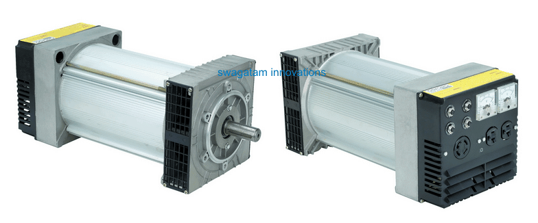
Instead of winding a vertical axis wind generator yourself, a simpler idea would be to configure the VAWT mechanism with a high watt generator or a dynamo through a correctly calculated gear or pulley/belt ratio.
For example, the above shown 10 kv dynamo has a specifications of generating 10000 watt at around 3600 RPM, which implies that if the a pulley ratio of 1:100 is configured, the dynamo would be able to produce the rated amount of power with the VAWT rotating at just around 36 RPM, which could be achieved perhaps even at wind speeds as low as 5km per hour.
How to Set Up the Turbines
The following diagram shows a rough set up design for the above explained implementation:
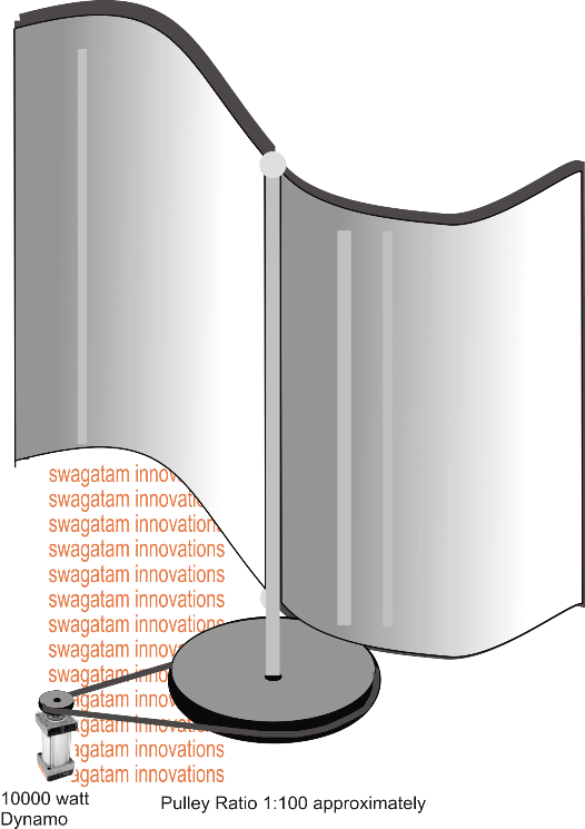
The figure above shows a simple vertical axis wind turbine model, the vertical helical turbine is designed to capture wind flow on one half of its span while allow free flow on the other half, causing the propeller to initiate a rotational movement with high torque.
Being vertical in its positioning the VAWT does not rely on wind directions unlike the traditional horizontal axis wind turbines. This advantage makes the VAWT sustain its operations under all wind conditions regardless of its direction of flow.
The central vertical axis of the turbine can be seen attached with a gigantic flywheel, which is supposed to be a lot bigger than the wheel attached with the generator shaft.
The bigger the ratio, the bigger would be the conversion even at minimal wind speeds.
With a ratio of 1:100, the generator could be expected to be generating at its full capacity and specification, with the VAWT moving at a meager 50 RPM or even less. This speed could be in turn achieved at wind speeds not exceeding 5 to 10 miles per hour.
Controlling VAWT speed using Shunt Regulator Circuit
The above explained set up is for facilitating efficient conversions at low wind speeds, but what happens when the wind is rapid or during stormy conditions.
If this situation is not taken care of can easy rip-of the generator winding and burn it within no time.
In order to control the VAWT speed at dangerous wind speeds, the following shunt regulator circuit could be used with the output of the generator for achieving a constant speed on the generator and the VAWT.
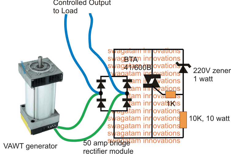
In the above figure the generator output is applied to a high current triac shunt regulator network through a 50 amp bridge rectifier module.
The value of the zener diode determines the control threshold, which is shown as 220V in the diagram. It means under no circumstances the voltage from the generator can exceed the 220V mark, and if it does the excess power is simply shunted or shorted to ground via the triac.
This ensures a controlled rotation of the generator even at formidable wind speeds keeping the entire system stabilized and safe.
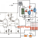
The above simple VAWT voltage regulator circuit could be also built using a MOSFET shunt regulator circuit as depicted in the following diagram.
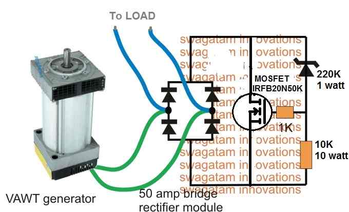
The working principle is same as above. When the VAWT output voltage tends to rise above the 220 V mark, the 220V zener begins conducting, which in turn switches ON the MOSFET. The MOSFET then begins conducting causing a momentary short circuit across the VAWT output. This causes the voltage to drop below 220V switching off the MOSFET. The cycle now keeps repeating continuously, enabling a constant 220V to the connected load.
If the generator used is a 3 phase type of generator, the shunt regulator shown above could be replaced with a 3 phase shunt regulator using SCRs.
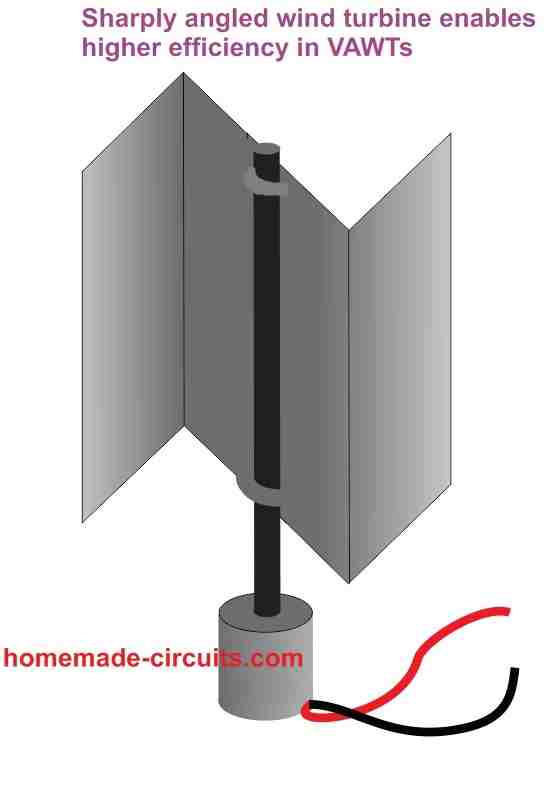
High Efficiency VAWT Turbine Design
Instead of employing roundish blades for the turbine, we can probably use a sharply angled blades for ensuring better aerodynamic efficiency, and for more effective wind capture and deflection, as shown below.
If you have any doubts regarding the discussed vertical axis wind turbine generator circuit, do feel free to express them through comments

Questions & Answers
Hi, looking at this project, can you provide dimensions of the turbine blades, the size of the rotating disc on the turbine.
I’m wanting to use this in my van to power a 12v battery.
Would you recommend a smaller dynamo and where to get it?
Is the booster circuit needed. What configuration would you suggest.
Thank you.
Hi, sorry, I do not have the the exact calculations, but you can easily find it through many online sources. The best method according to me, is bu trying the dimensions through some trial and error.
Yes a 12V dynamo can be tried, which can be purchased from any online store such as amazon.
Booster circuit will be needed if the windmill motor is specified to produce low voltage and high current, if it is the opposite then you might need a buck converter. Otherwise if the motor is rated to optimally generate an output matching the battery specs, then no external circuit will be required except the one presented in the above article.
hello Swagatam
do yo have by any chance something similar but for 3 wire generators ???
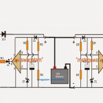
Hello Gustavo,
you can modify the concept in the following manner:
Hello Sir you seem to be someone that may be able to help, I made a homemade VAWT, on the bench with a voltage multiplier it outputs 21 volts DC@ 250 rpm’s but when I put it on the pole and hook it up to the battery bout all I can get with a stiff wind is 6 volts DC. The set up is 3 blades made in a Lentz configuration it spins freely with little wind, it has 9 coils wired in a star 3 phase. Do you have any suggestions of how to increase the hooked up voltage, I am only trying to charge a deep cycle battery?
Thank you.
Hello Mitchell, a voltage multiplier will not help, because it will show a higher voltages with insignificant current. Make sure to design the motor so that it gives the required amount of voltage without any multiplier circuit.
By the way what is the current output that you get for the 6V? This will let us know about the wattage of the output, if it’s high enough then you can probably try a boost converter for the required boosting.
Dear Sir,
I have done the vertical axis turbine with the 4 blades with 90 degree angle each other.Need 400W or little bit more capacity system with 12V out put.If there is a link to safe purchase Please not it.I'll try to join it with the solar system and hybrid to charge the battery back up.Calculation part also need to present in my project.I will send those things later.
Dear Chathura, sorry I could not understand your exact requirement?? if possible please clarify it again.