In this article I have explained a dual input hybrid solar and wind battery charger circuit using cheap and ordinary components.
The idea was requested by one of the interested members of this blog.
Technical Specifications
Good after noon sir am designing a " Solar and Wind energy harvest regulator circuit" which has two inputs and one output.
The PV solar panel ( 0-21V DC) and the other input is a wind turbine (15V DC).
The circuit must be designed for charging a 12v battery . the output current being delivered to the loaded battery must not deliver more than 3.5A.
My group and myself have gotten a few circuits off the internet and simulated them using pspice none of them is giving us the output current of 3.5 A. please sir can you please help us with examples of circuits which we can use.
The Design
In one of my previous posts I introduced a similar concept which enabled a battery to be charged from two sources of energy such as wind and solar simultaneously and without the need of any manual intervention.
The above design is based on PWM concept and therefore could be a bit complex and difficult to optimize for a layman or a new hobbyist.
The circuit presented here offers exactly the same features, that is, it enables the charging of a battery from two different sources, yet keeping the design extremely simple, efficient, cheap and hassle free.
So I have explained the circuit in details with the help of the following explanation:
Circuit Diagram
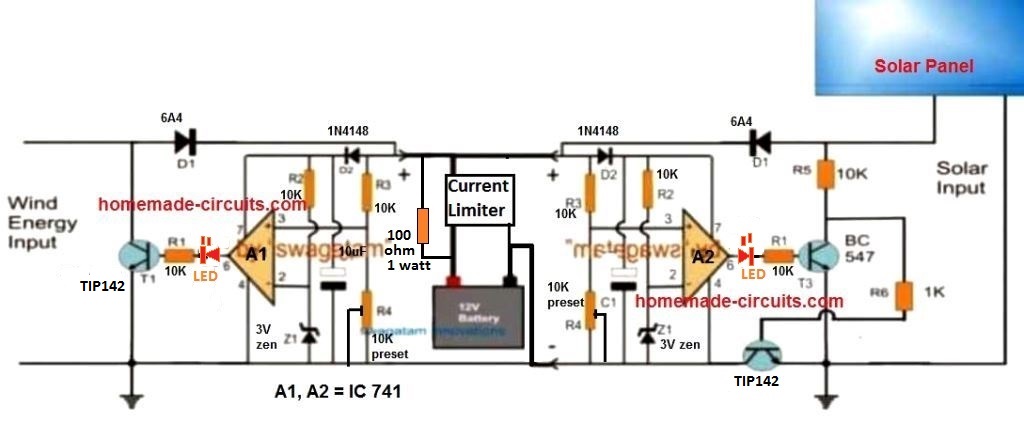
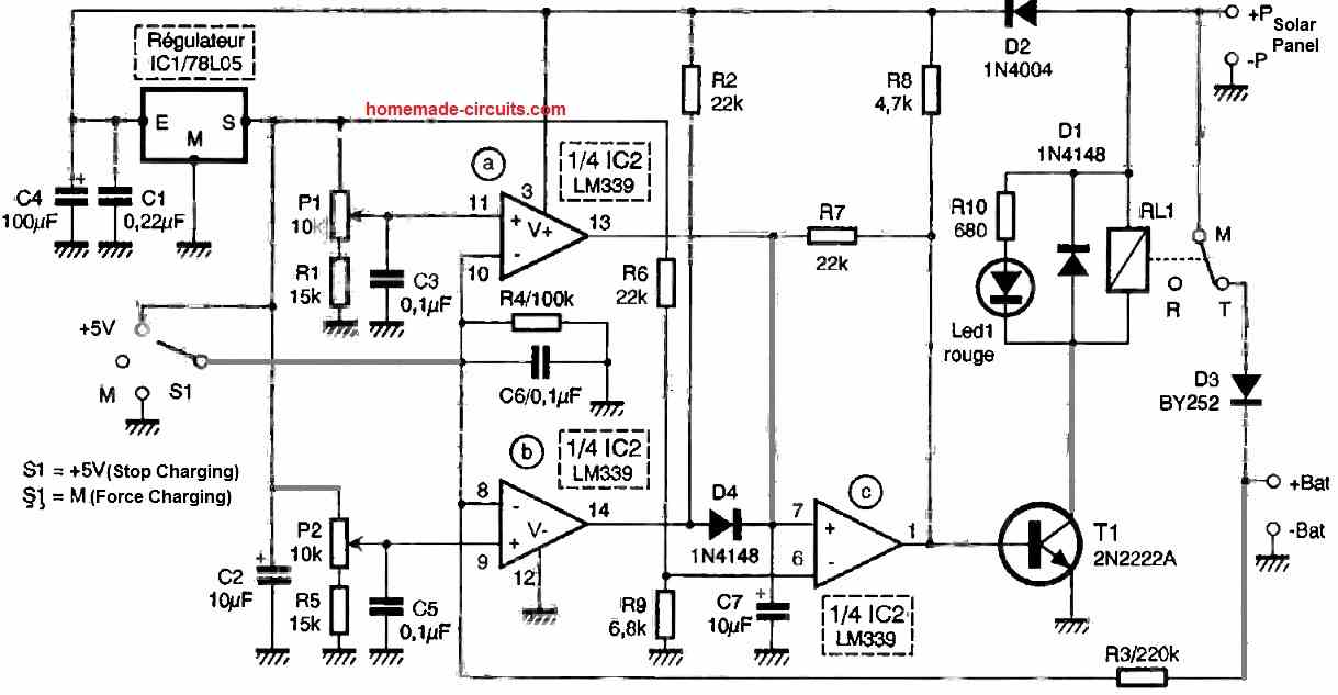
The figure above shows the proposed solar, wind twin hybrid battery charger circuit, using very ordinary components such as opamps and transistors.
We can see two exactly similar opamp stages being employed, one on the left side of the battery and the other on the right side of the battery.
The left side opamp stage becomes responsible for accepting and regulating the wind energy source while the right side opamp stage processes the solar electricity for charging the single common battery in the middle.
Although the two stages look similar, the modes of regulation are different. The wind energy controller circuit regulates the wind energy by shunting or shorting the excess energy to ground, while the solar processor stage does the same but by cutting of the excess energy instead of shunting.
The above explained two modes are crucial since in wind generators which are essentially alternators require the excess energy to be shunted, and not cut off, so that the coil inside can be safeguarded from over current, which also keeps the speed of the alternator at a controlled rate.
This implies that the concept can be also implemented in ELC applications also.
How the opamp is Configured to Function
Now let's investigate the functioning of the opamp stages through the following points:
The opamps are configured as comparators where the pin#3 (non-inverting input) is used as the sensing input and pin#2 (inverting input) as the reference input.
The resistors R3/R4 are selected such that at the required battery charging voltage, pin#3 just becomes higher than pin#2 reference level.
Therefore when the wind energy is applied to the left circuit, the opamp tracks the voltage and as soon as it tries to exceed the set threshold voltage, pin#6 of the IC goes high which in turn switches ON the transistor T1.
T1 instantly short circuits the excess energy restricting the voltage to the battery at the desired safe limit. This process goes on continuously ensuring the required voltage regulation across the battery terminals.
The opamp stage at the solar panel side also implements the same function however here the introduction of T2 makes sure that whenever the solar energy is higher than the set threshold, T2 keeps on cutting it OFF, thereby regulating the supply to the battery at the specified rate, which safeguards the battery as well as the panel from unusual inefficient situations.
R4 on both the sides may be replaced with a preset for facilitating easy setting up of the threshold battery charging level.
Current Control Stage
As per the request, the current to the battery must not exceed 3.5 Amps. To regulate this a standalone current limiter can be seen attached with the battery negative.
However the design shown below can be used with up to 10 amp current, and for charging up to 100 Ah battery
This design can be built using the following circuit:
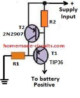
R2 may be calculated with the following formula:
- R2 = 0.7 / charging current
- wattage of the resistor = 0.7 x charging current
Parts list for the solar wind dual hybrid battery charger circuit
- R1, R2, R3, R5, R6 = 10k
- Z1, Z2 = 3V or 4.7V , 1/2 watt zener diode
- C1 = 100uF/25V
- T1, T2 = TIP142,
- T3 = BC547
- D2 = 1N4007
- Red LEDs = 2nos
- D1 = 10 amp rectifier diode or Schottky diode
- Opamps = LM358 or any similar
Simplified Solar, Windmill Hybrid Battery Charger Circuit
A very effective solar, and windmill combined hybrid battery charger can be built using just a couple of transistors, as shown in the following image:
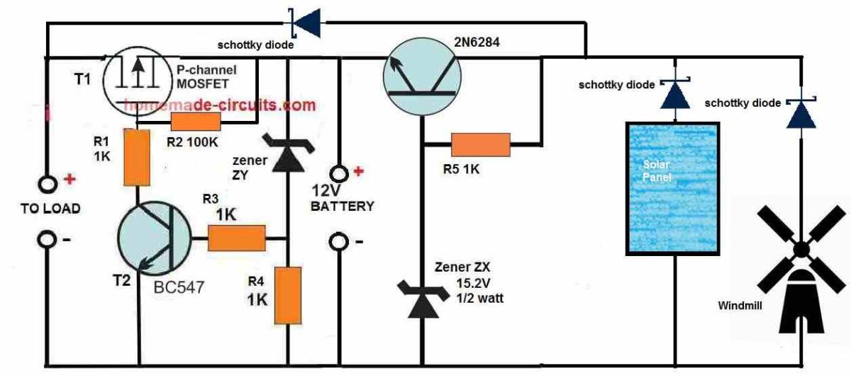
This is actually a simple yet very effective, full fledged hybrid charging system which will not only combine the solar and windmill power to charge your battery faster, but also make sure that the battery is never over charged or over discharged. That means, your battery condition will be always maintained efficiently ensuring a longer battery life.
Another great feature of this hybrid charger is that, the load can be operated simultaneously while the battery is being charged, without loading the battery.
Also, in case the solar/wind power is unavailable and the battery reaches lower discharge level, the load will be automatically cut off, to prevent over discharging of the battery.
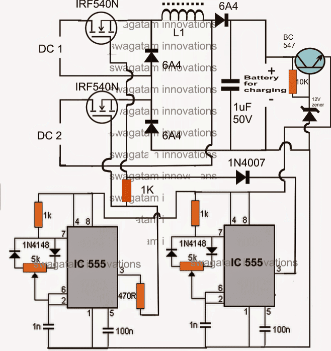
Double DC Input Hybrid Charger Circuit
A similar second hybrid design below describes a simple idea which enables the processing of two different sources of DC inputs derived from different renewable sources.
This hybrid renewable energy processing circuit also includes a boost converter stage which effectively raises the voltage for the required output operations such as a charging a battery. The idea was requested by one of the interested readers of this blog.
Technical Specifications
Hi, I am a final year engineering student, i need to implement a multi input chopper (integrated buck/buck boost converter) for combining two dc sources(hybrid).
I have the basic circuit model, can you help me to design inductor, capacitor values and control circuit for the chopper. I have emailed you the circuit design.
Circuit Operation.
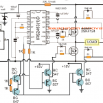
As shown in the figure the IC555 sections are two identical PWM circuits positioned for feeding the adjoining double input boost converter circuit.
Following functions take place when the shown configuration is switched ON:
DC1 may be assumed as the high DC source such as from a solar panel.
DC2 may be assumed as alow DC input source, such as from a wind turbine generator.
Assuming these sources to be switched ON, the respective mosfets start conducting these supply voltages across the following diode/inductor/capacitance circuit in response to the gate PWMs.
Now since the PWMs from the two stages might beset with different PWM rates, the switching response will also differ depending upon the above rates.
For the instant when both the mosfets receive positive pulse, both the inputs are dumped across the inductor causing a high current boost to the connected load. The diodes effectively isolate the flow of the respective inputs towards the inductor.
For the instant when the upper mosfet is ON while the lower mosfet is OFF, the lower 6A4 becomes forward biased and allows the inductor a return path in response to the switching of the upper mosfet.
Similarly when the lower moset is ON, and the upper mosfet is OFF, the upper 6A4 provides the required return path for the L1 EMF.
So basically, the mosfets can be turned oN or OFF irrespective of any kind of synchronization making things pretty easy and safe. In any case the output load would receive the average (combined) intended power from the two inputs.
The introduction of the 1K resistor and the 1N4007 diode ensures that the two mosfets never receive separate logic high pulse edge, though the falling edge may be different depending upon the setting of the respective PWMs of the 555 ICs.
The inductor L1 will need to be experimented with in order to get the desired boost at the output. Different number of turns of 22 SWG super enameled copper wire may be used over a ferrite rod or slab, and the output measured for the required voltage.

Questions & Answers
Very interesting Simplified Solar, Windmill Hybrid Battery Charger Circuit
My application is a remote trail camera that runs off a 12v lead acid. But this would give me greater flexibility.
How easy to modify it to give me the option as and when required to replace the lead acid with 3S3P lithium. So it can charge both up but seperatly (not at same time).
Hey, Thanks, and glad you like the above concept…
You can definitely replace the battery with a Li-ion type, especially in the second circuit, since it has a constant voltage charging, which can be further upgraded to constant current, and also it has an over discharge protection also…
You just have to select the solar panel specifications as per the battery rating.
For enabling lead acid and li-ion battery charging separately, we will have to include two separate voltage/current regulator chargers…
Sorry, I got the names mixed up, I can’t fix it anymore 🙁 🙂 Swagatam
No problem Deivis, it’s fine, it happens sometimes….
Hi, Swagatam, it’s great that you do things like this!
I plan to build a small solar and wind farm little by little. And I’m looking for a diagram on the Internet where it would be very easy for a beginner to gradually connect new modules (for example, several LCD screens for monitoring, and then monitoring via phone or computer (LAN, Wi-Fi) ). I also plan to gradually increase the power of the solar modules (the wind will remain the same all the time). I know how to make PCB boards and minimal small circuits and programming. Taking my time, I think it will be possible to assemble and construct something. Maybe you have some simple ideas or pre-made circuits where I can make my own after buying the elements. This would allow you to save costs and choose the options you want. Resources are limited, especially time, but little by little.. 🙂
Thank you
Hi Deivis, I will certainly help you to accomplish your plans.
But first it would be important for me to know how much load do you want to connect with the solar panel or the windmill, or simply what should be the maximum capacity of the windmill or the solar panel for your project.
Let me know about this then we can proceed with the projects…
Sir any charge Controller for micro hydro?
Hi James, please provide the micro hydro output specifications, I will try to help!
Sir for micro hydro a 220v D.C dynamo use for pelton Wheel and a 12v 55AH battery
If the voltage exceeds 80V in the simplified version, the transistors could get damaged.
Good day sir, I have a 12v D.C for my wind and a 23v solar panel, and a 55AH battery. Can I use the simplified version for my project
Good day James,
Yes, you can use the simplified version. However, the 12v from the windmill alone might not be able to charge the 12V battery, it should be around 16V minimum.
You might require around 5 amp current to charge the 55Ah battery within 12 hours time.
Hi Sir.
I am working on my bachelor’s thesis, and I had some challenges in designing the circuit. The project is to design a hybrid charger controller to charge 6-cells li-ion (battery pack). The renewable energy sources would be solar panels and an underwater current turbine. I need to include a controller in the circuit as far as I know. It’s because I will implement MMPT to my renewable energy sources. so, the buck-boost converter will not be enough.
After I did the literature review, I discovered that circuit design needs knowledge of power electronics and using tools such as MATLAB, and LTspise. Unfortunately, I am not that good at electronic design and wonder if I can get your help.
Best Regards
Hi Reem,
Designing a professional MPPT circuit can be quite complex, and my knowledge of MPPT concept is not good. So i am sorry, designing and explaining this concept appears to be beyond the range of my expertise.
However, according to me a buck or boost converters are equally very efficient way of managing renewable power sources.
Good morning, Sir, I have to create a circuit similar to this one for the school do you have any variation that can be used on multisim. thanks
Hi Jadell,
Sorry I have no idea regarding any variations in the circuit that can be used on multisim.
Good Day, I wish to build the above circuit. Do you sell the PCB or do you have a Gerber file available so I can get the board made.
Most interesting article, as always.
Many Thanks for sharing your time with so many others.
Kind Regards. Paul, In the uk.
Thank you Paul, you can certainly build the first concept, however I do not have the PCB design or the Gerber file for this circuit. You may have to consult a good PCB designer to get it designed for you.
Hello sir, my group is currently involved with an engineering project which uses the circuit you’ve improvised above but with an Arduino-controlled LED that acts as a road lamp. Do you have any idea how we could implement a circuit like that?
Hello Ivan, It can be difficult for me to solve your query, because my Arduino knowledge is not good at all.
Hello Swagatam, no worries. I just wanted to know how to connect this Arduino-controlled LED to this circuit haha. It’s fine!
Although I am not 100% sure, you could probably implement something like this:
The LED section could be replaced with your Arduino controlled LEDs.
Dear Mr Swagatam
I am busy with an engineering project regarding renewable energy and would like to use your suggested circuit combining wind and solar, if you don’t mind? I am simulated the circuit with N1 Multisim first before constructing the actual circuit and there is a few questions i would like to ask concerning the simulated results. The collector current (wind) of the TIP142 is running at 9.5A when shunted. Surely when the Solar output is higher and there is still significant current produced by the turbine shorting its output to ground would result in component (T1 in your circuit) failure? Please help me to understand how this can be done without significant resistor/s to dissipate the energy and would shorting the turbine’s output not cause it to
fail?
Hello Alex, shorting an alternator output to control over voltage is the recommended solution.
If you think TIP142 cannot handle the current, then you can replace it with a MOSFET or a TIP135 transistor.
Hello, want to ask about the current controller circuit. Why is TIP35 for T1 used instead of 2N2907. And regarding the design of the circuit what is it based on? Meaning where i could read on the theory behind this circuit.
Hi, TIP36 is the main load handling device therefore it has to be a high current type. 2N2907 is positioned to ground the base of the tIP36, therefore it can be low current type.
You can read more regarding this circuit, in the following article:
2 Best Current Limiter Circuits Explained
Sir, Plzz give more details on current limiter circuit ( for 3.5 A) as given. Like what it would be… Resistor or what?…. Its rating and all kind of idea to limit the current Upto 3.5A. Plz sir, I really need this.
Zeel, the current limit circuit is already given in the above article. 3.5 A limit can be calculated through the formula given under the current limit circuit
Good morning Swagatam I hope you are fine. I would like you to provide me with a 12 volt relay circuit, when connected to the source it gives one pulse for a second and then stops, although its coil is still connected to the source, it does not return the pulse except by cutting the source and replacing Connect it again.I have an app that needs that. Thank you.
Abuesak, please post your question under delay timer article, because the above article is about solar wind battery charger, unrelated to your question.
Good day sir, thank you for sharing. I would like to ask will the circuit still works if I use a smaller DC motor that produces a lower voltage output for the wind turbine? I would like to a charge a small battery bank of a 3.7v 3000mah lithium ion battery. If not what changes do I need to make? Thank you very much.
Thank you Maber, you can try the following simple design for regulating your motor output
The value of ZD will decide the regulation output voltage…..try 6V zener first and see what output you get, and accordingly select the most appropriate one….
I would like to ask does this circuit directly connects to the battery? or do I connect it to the circuit above?
Also does the circuit stays the same for the solar panel side? I learned that I only need 5V in charging a 3.7v lithium battery.
I’m fairly new in electronics.
Thank you as always.
The output side can go directly to the battery, and the input side with the motor output through a diode 1N4007, if the motor is a DC motor.
Actually it should be precisely 4.2V for charging a li-ion cell, so you can experiment with the zener to get as near as possible to the 4.2V mark
First of all, thanks for the valuable information. My question that I would like to present is whether the scheme of this circuit is compatible for charging 6 lithium batteries connected in parallel, the voltage of each of them is 2 volts and a current of 500 amperes. If the scheme does not match, I hope to provide me with a proposal awaiting a response quickly. Thank you.
You will need a buck converter for your application, as given in the following article. However, for 500 amp you may have to suitably upgrade the transistors and coil wire thickness accordingly
PWM Solar Battery Charger Circuit
Great effort and excellent, thank you for your interest.
Good day,
i am looking for a 48v circuit for a wind turbine.
the unit have to have some functions:
1 ac input 3 phase 90volt x3
charge batteries to 58v and when it stop to charge it must bridge out 2 of the ac circuit to stop the turbine.
Sorry, could not understand your specifications, explain with proper details.
Good day. Thank you for replying.
I got a 48volt solar system working. I got 20 x 100ah batteries connected. The solar is working great but i need some more input I hot myself a wind turbine.
The wind turbine got 3 x 90 volt ac output. I want to connect it directly to the batteries to charge with its oen charger.
The only thing is as soon as the batteries gets full it must stop the turbine. To stop the turbine you just bridge ant of the 3 ac wires then it stopped the turbine
Good day, here’s the simple design that you can implement:
Thank you very much. Sorry for asking stupid questions but what cap do i to use at C1 and what IC?
Last question. Do i add this with the charging circuit at the same time. I got the circuit with the green and red LED.
No problems, you can use 100uF/25V for C1.
You can the charging circuit between the output of this circuit and the battery.
There’s one correction needed in the above design. The resistor R5 should be placed at the right side of the R3/D2 junction, so that the windmill voltage/current enters through this resistor for powering the entire op amp circuit
hello sir,
I commend you for your effort sharing your knowledge, I am interested in your article and as such I want to build my solar wind inverter and am a novice, can you pls take me through the rudiments, most especially how to configure an ic
Hello Aanu, you can refer to the following articles for all the details:
https://www.homemade-circuits.com/how-to-make-solar-inverter-circuit/
https://www.homemade-circuits.com/designing-solar-inverter-tutorial/