This article will illustrate a simple procedure to devise an unregulated 50V switching SMPS symmetric power supply of 350W. This unit can be substituted with the standard audio amplifier power supply to reduce expense and also the weight. The proposed power supply works as a half-bridge with no regulation.
Written and Submitted by: Dhrubajyoti Biswas
Mosfets as Power Devices
My power supply relies on two N MOSFET and run by IR2153 integrated circuit. The IR2153 is powered by a power resistor of 27K 6W. The ripple at full load is recorded below 2V.
The use of Zener diode (15V) ensures voltage stabilization and the operating frequency is set to 50 kHz (approx.).
At the point of the input, I have placed a thermistor to force a check on the peak current when the capacitor is getting charged.
This same phenomenon can be found in AT/ATX power supply unit of a computer. Moreover, to ensure low leakage inductance and full voltage output, the first half of the primary is wounded in 20 turns followed by the secondary wound.
Also to assure safety in the system, do be sure to connect the output (center tap 0V) to the earth.
Chokes for Filtering RF
The chokes used in the design will facilitate removal of RF output ripple. The number of turns and the core which is found in PC supply is not a critical factor.
Additionally, the 6k8 resistors at the output section is used to discharge capacitors after it is switched off and this way it helps to prevent the voltage increase during no load.
The proposed Switched power supply 2x 50V 350W operates in single switch forward topology. It has an operating frequency of 80-90 kHz and has IRF2153 control circuit which is very much similar to that of US3842. However, the duty cycle is lesser and is limited to 50%.
Rewinding an ATX Trafo
The Tr1 transformer was devised by rewinding the SMPS ATX transformer and its primary inductance is 6.4 mH (approx.).
The core of the system has no air gap and the primary inductance is further broken in two parts: The first half is the wind and the second is the winding.
Moreover, it is also feasible to deploy the original primary bottom half without rewinding. This type of power supply aptly suits for power amplifier applications.
If required it may be also safeguarded against overload or short circuit and the voltage of the output could be stabilized. The Feedback of the system may be enabled through the help of optocoupler.
It is important to note that in regard to 350W power, care should be taken that in the conductive state the typical resistance should not cross more than 0.8R. MOSFET can also be used to lower the point of resistance.
Interestingly, the smaller the resistance better is with the system.
The voltage tolerance is in the range of 900-1000V. In the worst case scenario 800V can be used. Considering this, the best MOSFET I found was SPP17N80C3 or 900V IGBTs.
Circuit Diagram
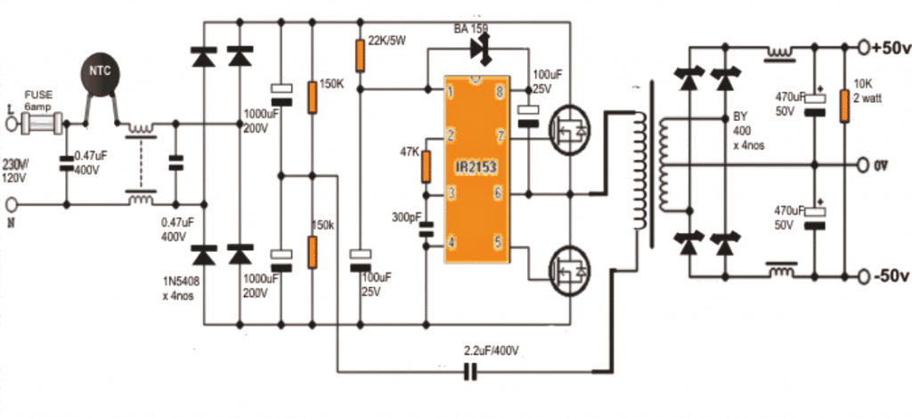
Coil Winding Details:
- The main SMPS transformer which can be seen integrated with the MOSFETs may be wound on a standard 90 by 140 square mm ferrite bobbin core assembly.
- The primary side winding consists of 40 turns of 0.6mm super enameled copper wire.
- Remember to stop after 20 turns, put an insulation layer with an insulation tape and wind the secondary winding, once the secondary is wound, insulate it again and continue with the remaining 20 turns over it.
- Meaning the secondary winding gets sandwiched between the primary 20 + 20 turns.
- The center tap of this 20+20 may be connected with the body of the SMPS for an improved stabilization and cleaner outputs in terms of ripples or buzzing interference.
- The secondary consists of a center tapped 14 x 2nos turns made by winding 0.6mm super enameled copper wire.
- The input and output filter coils may be wound on ferrite torroidal cores. The paired winding must be wound on the same individual torroidal cores using 0.6mm super enameled copper wire with 25 turns on each arm of the relevant supply terminals.
Update:
The above design 350 watt SMPS circuit was further improved by one of the dedicated members of this website Mr. Ike Mhlanga. The complete schematic of the same can be witnessed in the following figure:
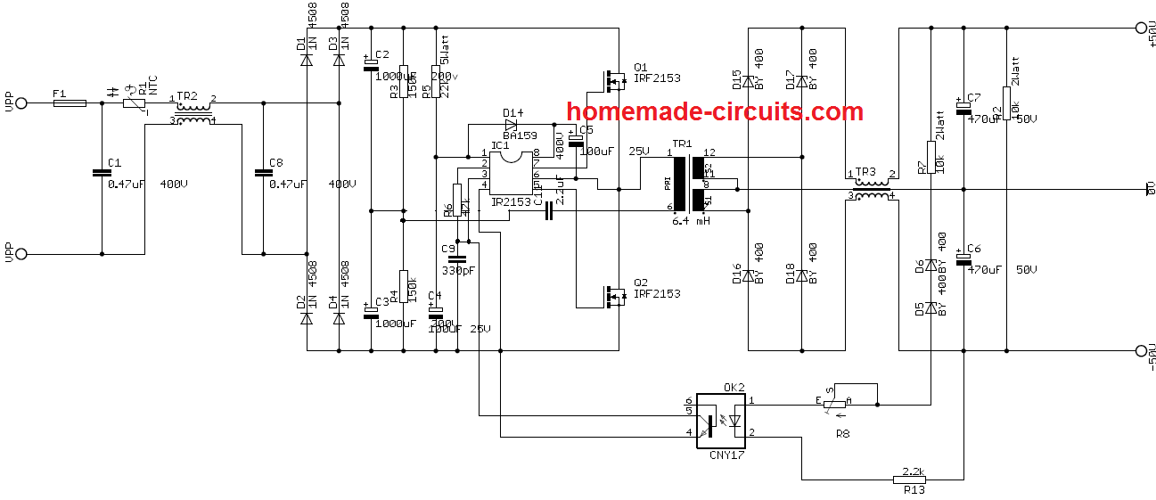

Questions & Answers
Sir,
Above circuit can be use for audio Amplifier which u have given . in this article the difficult part is transformer. Is it possible for you give a separate topic on this with picture
Thanks and regards
style, there's nothing difficult in it if you read and follow the instructions carefully, if you have problems you can always ask me for further help….
Dear Swagatam,
I would like to sympathize with style for his difficulties in understanding the transformer winding details. Though the idea behind this article is very innovative and commendable, the narration is very sloppy and written in poor English with a lot of grammatical errors. I am not criticizing your post, but I suggest a more detailed proof reading of technical articles for a better presentation. For an experienced hand it is okay, but for a less initiated person or a novice, it can be very confusing. A few drawings or pictures would have made a lot of difference, as suggested by style.
I congratulate you on the excellent articles you have written in your blog, keep it up.
Regards
Dear Chinmoy,
yes the article is a rephrased version and may have a few errors since it was written by a person with only general electronic knowledge.
the circuit actually has nothing complex in it.
the IC is a half bridge IC which generates a push pull output for the connected mosfets, which in turn switch in a full-bridge manner due to the involved dual AC input configuration.
this results in an efficient induction across the output winding
if you can go through the datasheet of the IC, you'll be able to get a better picture of its functioning details
Thanks a lot sir..
You have any topic related to transformer making . I mean to say like calculation of E and I core calculations, bobbins size calculation, what size of gauge wire to be use. So that I can make a different voltage and wattage of transformers.
Thanks and regards
style, presently I do not have all the info regarding ferrite transformer designing, once I collect it will surely update them in this blog…
Dear sir ,
Sir I want power supply 50-0-50. /12 amps. Wat would be the gauge of secondary coil and number of turn
Thanks and regards
Dear sir
What is the primary frequency because one place its mentioned 50khz and in another place 80- 90 kHz
Second thing what is the primary current to the transformer
Thanks and Regards
Dear style, it doesn't make much of a difference whether it's 50 khz or 80 khz, for precise answers you can calculate it yourself by referring to the IC datasheet and by inserting the 47k and 300pF in the given formula
Dear Sir
For making PCB what specification i have to tell to shop . i want to make 1000 watt stereo
I want good quality COPPER BOARD
Regards
Dear style today all standard PCBs are made on glass epoxy base, so presently it's the best both quality wise and cost wise.
What if I use a ferrite EDT49, whether the number of turns on the primary and secondary side as you say?
And if the switching frequency is 90kHz, if there is a change in the circuit or component changes?
you can use any EE core as long as it accommodates the winding comfortably it'll be fine.
you'll have tweak and adjust the 47k/300pf values for getting the desired frequency with some trial and error.
hello sir,instead of ferrite core can I use iron core which is used in transformer ?
hello Rahul, iron core will not do, it has to be strictly ferrite
Dear sir.. what is the size of ferrite core…
a 15mm EE core should do the job, the size actually does not matter as long as it accommodates the winding comfortably.
Sir I have one system which is operational on 110volt 60 hz.. What can I do to make its operational,as we have 220V 50hz.. Help me sir
you may have to buy a VFD or build yourself one as given here:
https://www.homemade-circuits.com/2013/09/single-phase-variable-frequency-drive.html
Sir, System is 120 Volt and 60 hz. Can it be operated with 120 volt 50hz. The system power supply is smps based . does it effect the systems any way. And Sir , power rating is 500 watts. Can I use this give circuit for this.
Thanks n regard
Style, in the previous link of a VFD circuit, you can adjust and set the output to 120V 60 Hz or to any desired level as per the load specs, therefore according to me it would be suitable for your application too.
the power is related to the mosfets which can be upgraded as per the requirements.
Sir,
What will be effect on system ( Panasonic amplifier 7.1) if we give 50hz instead of 60 hz. Power supply is smps based.
2. The source of mosfet be given 110volt .but how can I get 110 volts .
Please help me
Hi Style,
frequency change will not make any difference to an SMPs, for getting 110v you can eliminate the center tap of the above circuit and acquire the required 110 V from it.
please boss i need your help now, i want you show me how to build power inverter, if you teach i will be happy for you?
you can go through the following article, it has most of the info regarding the subject:
https://www.homemade-circuits.com/2013/03/how-to-design-inverter-basic-circuit.html
Sir,do you have a layout for this schematic sir?
sorry, no PCB layout for this…
Thanks for this sir, though i saw it several days ago;the reason why i did't consider it much is all about the IC, i think i will a serious problem to find it in my local shop here in Tanzania, is there any other way around without involving ic?
Thanks though sir, thanks
Raymonds, unfortunately there's no easy alternative to the above IC because it's a specialized half bridge driver IC…and does not depend on a center tap trafo, rather uses a two wire trafo for an efficient performance.
Hi Swagatam…
In my Country, IR2153 IC is still rare. Because IR2153 IC is for a PWM Generator, can i change the IC to LM555 or CD4047?
Hi Naufan,
LM555 or CD4047 will not work, because these are not equipped with high-side drivers…..these are just ordinary oscillators, while IR2153 is a specialized half-bridge driver IC…
hy,,,swagatam..u r genius
can i use troidal core ring.?? plzz give me ring size.
thx in advance..
Hi Nitin, a torroidal core will work, but might require an entirely different winding data which I am not sure how to calculate….you can try it and find the most optimal results with some experimentation.
thx 4 your adwise..i will try n post result.
Dear Swagatam, I would like to build a regulated smps for my audio amplifier which will be capable of around 400 watts, and having a voltage of 50-0-50. If possible using the TL494 or similar device. I have quite a few ATX power supplies at hand and can salvage parts from them.
Thanks in advance
Dear Silvio, you can try the following inverter design, just replace its trafo with the a ferrite trafo which is discussed in the above article for obtaining the intended results:
https://www.homemade-circuits.com/2014/06/smps-2-x-50v-350w-circuit-for-audio.html
Sorry for misleading you I was referring to a mains operated power supply.
yes I understood, actually you can configure the supply pins of the TL494 in the similar way to the above shown design. that is connect the positive pin of the TL494 just as pin#1 of the IR2153 is configured…this might just work
I appreciate your interest, however I am sorry, that would be difficult at the moment due to lack of time!
Hi!
I have a question about the two capacitors of 1000uF (200V). Can I use two 470uF (200V) instead of two 1000uF (200V)?
lower value will reduce the current at the output….the value of these caps determines the output current
With two 470uF I can get 4A?
it will need to be calculated, most probably it may be possible to get 4A
Hi!
I thought of doing so circuit (with these components):
substituting:
the first capacitors 0.470uF (400V) with 0.100uF (400V)
1000uF capacitors (200V) with 470uF (200V)
The 2.2uF capacitor (400V) with 0.5 uF (400V)
Potrebe work?
To me I need a single output of 50V 3-4A and no more than 200W.
You can do with these changes?
THANK YOU!
It should be exactly as shown in the diagram, other values could produce inefficient results
Instead of IRFP460 can I use IRFP260N?
please check their I and V specifications, if they match then you can interchange the two.
Hello Swagatam,
I'm new here and I'm not sure if you have already posted the circuit that I'm looking for. I need a power supply/inverter/smps with 12VDC input (from car battery) with an output of +50VDC & -50VDC at least 10ampere current capacity or more. Much better if the circuit is configured in SMPS.
Thank you and more power to you….
Hi Roberto, you can try the above explained concept with some modifications.
Instead of the mains you can apply 12V to the left hand side circuit…and you will need to modify the primary/secondary winding of the transformer.
For the primary side you could try around 5 turns and for the secondary 20 + 20 turns
the turn ratio might require further analysis and modifications, since it's not calculated by me precisely
Hello Swagatam,
My name is Prince Jose… This is a nice diagram. I want +/-90v 8A, how i can make it with you diagram, and also can i change the winding wire thickness…..