Here we study a simple IC 555 based monostable circuit whose output monostable time duration starts only after the input trigger is released thus making sure that the trigger ON time duration is added with the monostable's pre-programmed ON time duration. The idea was requested by Mr. John Brogan
Technical Specifications
I would like to know if I could hire you for a very simple project. This is to help me learn circuits.
I am looking for the following type of circuit (see below). Could you let me know what it would cost to design?
There will be 4 pins on the circuit board. 2 pins on the left side of the board, 2 pins on the right.
When someone closes the circuit of the LEFT side of the board, either momentarily, or for however long they keep the circuit closed, the pins on the RIGHT side of the board close *PLUS* 2 minutes after the time the circuit on the LEFT side of the board is opened. (that’s the part I’m stuck on – how to make a circuit stay closed for “n” minutes past the time another circuit is opened.
Please let me know what you would charge to diagram this and list the parts I need to buy to make this.
Thank you!
John Brogan
Colorado
The Design
In other words, the above request demands a monostable whose output on state delay will initiate only once the input trigger is released, meaning suppose the monostable is designed to produce a delay of 2 minutes, and let's assume the input trigger hold time to be x minutes, the total delay at the output pin3 of the IC should be then = 2 minutes + "x" minutes.
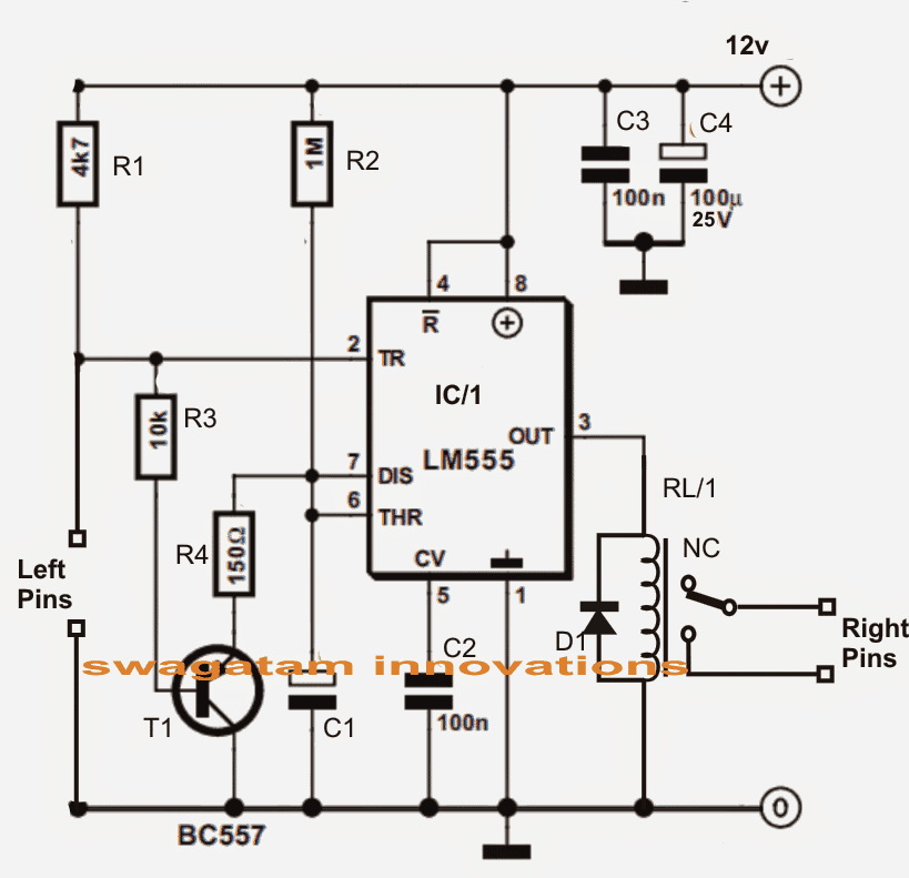
The design may be simply configured by adding a PNP stage to a standard IC 555 monostable circuit.
Referring to the figure below we see a standard IC 555 monostable circuit which produces an output high for a time delay determined by R2 and C1. This initiates each time pin2 is grounded momentarily or may be for some relatively longer period of time.
However normally this would happen as soon as pin2 is grounded without considering the trigger ON duration, and we don't want this situation for the proposed design.
The issue is effectively remedied by the inclusion of the PNP device T1 across the shown position of the circuit.
As suggested in the request when the left pins are closed, T1 is allowed with a negative bias forcing it to conduct.
The above condition allows the output to go high but shorts the timing capacitor C1 via T1 emitter/cpllector so that it is unable to charge until the left pins are opened by the user.
Once the left pins are released, C1 is allowed to charge and initiate the monostable counting operation wherein the relay actuates and closes the right pins for a total duration of the set two minutes plus the duration for which the input was held closed.
Circuit Diagram
IC 555 pinout Specs


Questions & Answers
Please Swagatam, i need a monostable circuit that will make pin 3 high for say 10 second when pin 2 is momentary grounded or held grounded for a long time( say more than 3 minutes). Pin 3 should go high again if pin 2 is taken from ground and the grounded again.
It is for a project which uses an infrared obstacle sensor as input. When the sensor senses a hand a light comes ON and stays on for 10 seconds after which the light will go off even if the hand is still there. To switch on the light again, the hand should be moved away and brought back for the sensor to detect.
Hi Dan, you can try the following design
Remove the 1M and replace it with your IR detector device. Adjust R3/C2 accordingly for the 10 second output delay.
The circuit powers up as soon as I connect the power to the circuit irrespective of the value of the capacitor at BC557. However I’m able to achieve the hold/off time by changing the capacitor at BC547. Also this capacitor is taking way too long to discharge. Hence I have to wait for a very long time to restart the circuit or discharge the capacitor at BC547. Please advise.
That shouldn’t happen actually, because the moment power is applied the BC557 gets disabled due to the base capacitor. If BC557 is disabled, BC547 cannot get the base drive and the associated stages also cannot function. Please add a red LED in series with the BC557 emitter lead, this will prove the behavior of the BC557.
To discharge the BC547 base caapcitor quickly, you can add another 10k directly across BC547 base/emitter
Hello Sir,
I’ve a 30 KVA generator and its operation is fully manual at present. I would like to implement a simple auto OFF when the EB power supply is back.
A delay timer to control the fuel solenoid whenever the EB power is back. The soleniod should be latched only after 10 secs after the EB supply resumes and latched only for 10 secs (Until the genset goes off). This cycle should occur only once or every time there is a power failure and resumption from EB.
I thought of using a AMF and it turned out to be expensive. Kindly suggest any other most optimal way to handle this.
Regards,
Jagadish S
Hello Jagdish,
you can probably try the following design:
Thank you for this circuit. Is there any way where I can change the time delay (Wait & Latching). Since the power to the Solenoid is close to 10A would it create any problem for the IC? What is the current rating required in this case to power the whole circuit. Can I also connect a relay in place of the solenoid disconnect the high current load on the circuit.
Please advise.
Regards,
Jagadish S
Yes you can change the timing as per your preferences.
You can adjust the T1 base 100uF to change the switch ON delay, and you can modify R3/C2 to alter the output switch OFF delay.
You can add a relay at pin3 exactly as shown in the article on this page, which will allow you to use higher rated loads
Hi Swagatam,
I constructed the circuit as per your design. Initially the circuit just behaved the way you had mentioned. But after testing it for a couple of times the circuit is not powering on without me manually triggering it (PIN2). Also I have grounded PIN 5 using 100nF(104) instead of 10nF(103).
I thought the chip failed and replaced the chip and also replaced the transistor but later figured out that I have to manually trigger the circuit. Please advise what could be wrong.
Regards,
Jagadish S
Yes, I waited for more than a minute just to be sure if there is a delay in switching ON. But the trigger never occurred. I had to manually trigger it to ON status and once the timer is ON it is working as desired. Also connected a 100K in parallel just to be sure but no luck.
Please advise.
Then it’s probably due to the slow current falling edge at pin2 which is not suiting the IC 555 triggering.
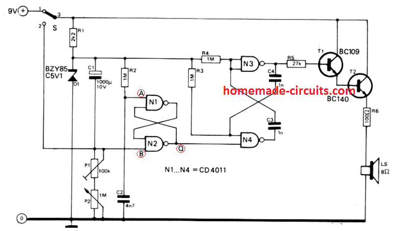
In that case we will have to eliminate the IC 555 concept and use a IC 4049 CMOS version, but since the time delay requirement is quite small, a transistorized version should be tried first, please try the following and check if it works satisfactorily or not.
The two capacitor values decide the delay ON and delay OFF timings, which could be adjusted as per preference.
When power is applied the BC557 base capacitor prevents it from conducting. When this capacitor charges it allows the bc557 to conduct. This conduction allows the BC547 base to get the biasing voltage via its 100uF capacitor, and the BC547 now switches ON. This also switches ON the relay.
However after sometime as the base capacitor of BC547 charges up, it stops the bc547 from conducting and the relay gets switched OFf
In that case how come the circuit was powering on initially when I built it and tested for a couple of times. I never had to manually trigger the Left pin. Also from the first reply you had mentioned to me to try combinations of capacitance at T1 Base to achieve delay in Switch ON. So a trigger was never required. Are we missing something in this exercise by any chance.
Please advise.
Actually the comments are presented separately to me so I am unable to see the previous conversations while answering them. So I probably lost track of the previous threads and I referred to the diagram which is published in the article.
So coming back to the new diagram, yes it should start at power switch ON. It might have stopped due to some stored charge in the base capacitor of the BC547. Add a 100k in parallel with the BC547 base capacitor and check the response.
But the monostable delay response will work only for power switch ON, it won’t happen during power failure.
I want correct my previous comment. The initial switch ON is not related to capacitor discharging fully. It could be because the monostable requires a quick rising edge voltage to trigger. Since the BC547 is activating slowly this might be causing the initial switch ON problem.
By the way Did you wait for 10 seconds after power switch ON, because as per your request the monostable is designed to initiate after some delay and not instantly when power is switched ON
Hi Jagdish, the output of the circuit is not intended to start when power is switched ON. The idea of the circuit is to ensure that the monostable counting begins only once the “left pin” points are released. That means, to initiate the monostable you will have to close the “left pin” gap manually, but the output delay will begin only when the left pin points are opened or released.
…for example suppose the monostable output delay as per C1, R2 is 10 seconds, and if the “left pin” is closed and released after 5 seconds, then the total output delay will be 15 seconds, although in normal monostable this would been 10 seconds only, regardless of the closing time of the “left pin”
Hi Swagatam
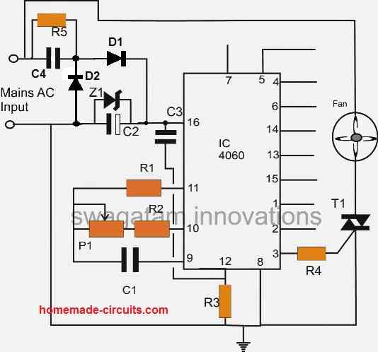
A more simple delay power off circuit can be used:
The delay time may be controlled with the resistor and capacitor.
Thank you Abu-Hafss,
I did not use transistorized circuit because their time delays are not accurate and for 2 minutes delay will require a relatively larger capacitor, which will in turn be prone to higher leakage issues and more unreliable timing.
I have a few transistorized timer circuits discussed here:
https://www.homemade-circuits.com/2012/05/simple-delay-timer-circuits-explained.html
However I have recently cracked the method of achieving high accuracy even for these transistorized circuits, The secret is to allow or force complete discharge of the timing capacitor immediately each timing the set delay lapses.