An autotransformer is an electrical transformer which consists of only a single, continuous, non-isolated winding, with tapped terminals across various points of the winding. The winding section between the taps that correspond to the mains AC is applied with the mains AC supply, while the remaining taps are used for getting the desired output voltages, in accordance with their winding ratios.
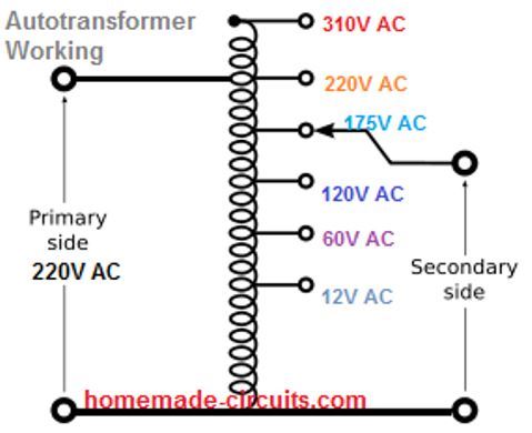
These output voltages may range from levels higher than the input supply and lower than the input mains AC, depending on the winding turn ratio across the relevant tap points..
The word "auto", is inspired from the Greek term "self" which relates to the functioning of a solitary winding coil across the whole transformer, without involving any kind of automatic mechanism.
In an autotransformer, tapped sections of a single continuous winding functions as both the primary winding and secondary winding of the transformer.
Difference between Auto-transformer and the Step-Down Transformer
Typically in any standard step-down transformer we find two completely separate winding coils in the form of primary winding and secondary winding which are electrically isolated, but magnetically coupled to each other, as shown below.
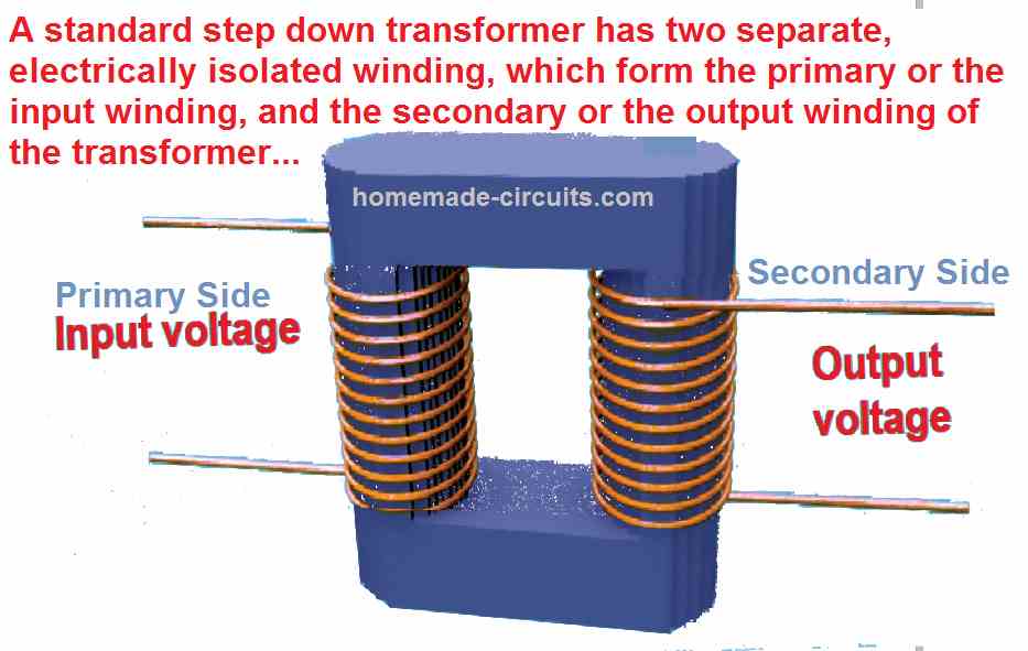
Here, the ratio of the winding across primary and the secondary decide the amount of voltage and current transfer between the two winding through magnetic induction.
Meaning, if suppose the primary has 10 times more number of turns than the secondary, then a 220 V AC fed at the primary will cause a 10 times stepped-down lower voltage across the secondary, equal to 220 V/10 = 22 V.
Similarly, if a 22 V AC is applied to the secondary, will cause a stepped-up 220 V to generate at the primary side.
Contrary to this, in an auto-transformer there's a single continuous winding divided into various voltage tappings, which determine the different voltage levels across the entire winding, as shown below.
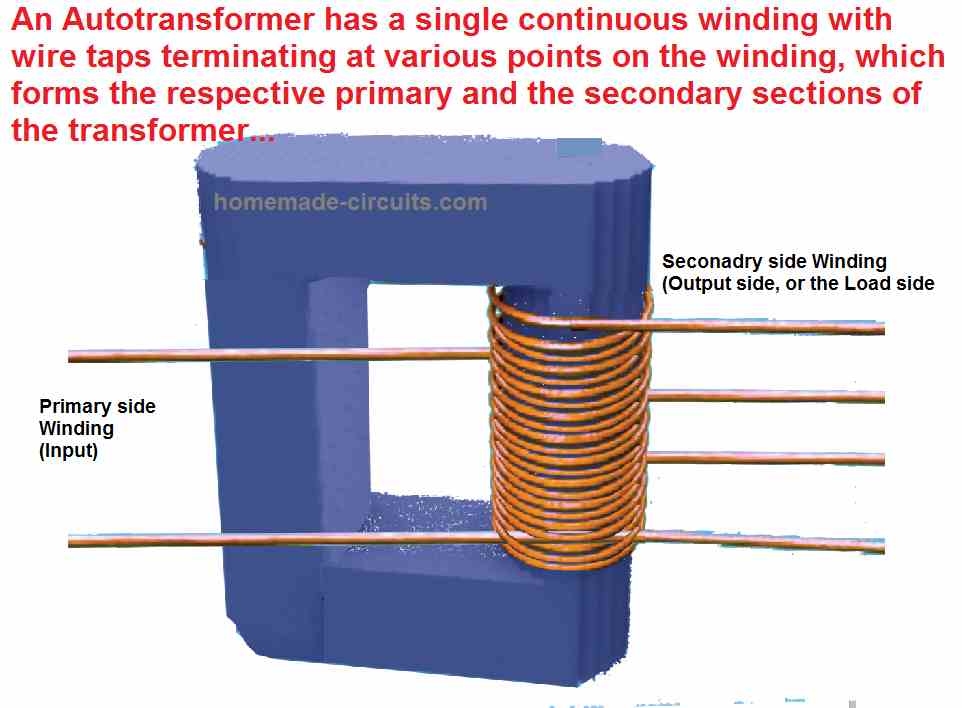
All these tappings are not electrically isolated, but can be magnetically energized just like our standard transformer, enabling proportionate amount of voltage and current sharing across the sections, depending on the ratios of the winding between the tappings.
How to Make an Autotransformer
An autotransformer can be built using the same calculations as done for a normal step down transformer, except the secondary side.
In fact making an autotransformer is much easier than the standard transformer, since here we can eliminate the secondary side winding, and use a single primary 300 V or 400 V continuous winding.
So basically, follow all the steps explained in the following article, just skip the secondary side calculations, and implement only the primary 220 V side calculations.
Use 400 V for the primary volts, and 1 amp for the current. Once wound, you can attach taps across various intervals of the winding for acquiring the desired stepped up or stepped down voltages.
Advantage and Disadvantage of an Auto-Transformer
In an autotransformer winding we normally have a minimum of 3 taps that are electrically terminated as outputs.
Due to the fact that a single winding functions both as primary and secondary, autotransformers have better advantage of being smaller sized, lighter in weight, and more affordable than typical double-winding conventional step-down transformers.
However, the disadvantage of an auto-tramsformer arises from the fact that none of its winding outputs are electrically isolated from AC mains, and may inflict a lethal shock when touched in swithed ON condition.
Among the other advantages of autotransformers are its reduced leakage reactance, reduced losses, lower excitation current, and enhanced VA rating for any existing dimension and bulk.
Application
A good example of an auto-transformer application is the tourist's voltage converter, that enables the traveler to connect 230 V appliances on 120 volt supply sources, or the opposite.
An autotransformer having several output taps could be utilized to adapt the voltage at the end of an extended distribution circuit to counter any surplus voltage drop. The same situation could be automatically controlled through an electronic switching circuit.
This is normally implemented through an AVR or an automatic voltage regulator, that automatically switches the various taps of the autotransformer through relays or triacs, for compensating the output in response to the changes in the line voltage.
How it Works
As discussed above an autotransformer includes just one winding with 2 end terminals.
There may be one or more terminals in between as tap points for getting the stepped up/down voltages across the tap points. In an auto-transformer we find the primary (input) and secondary (output) section of coils have their turns in common.
This the part of the winding shared by the two primary and secondary is usually, known as the "Common Section".
Whereas, the part of the winding extending away from this "common section" or the section that is not shared the primary and secondary is usually, known as the "Series Section".
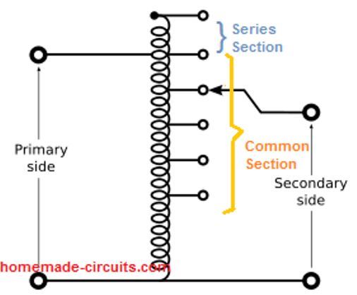
The primary (input) supply voltage is connected across two of the appropriate terminals, whose rating or specification corresponds with the input supply range.
The secondary (output) voltage is obtained from a pair of terminals or taps, one particular terminal among these is normally in common, both to the input and the output voltage terminal.
In an autotransformer, since the entire single winding is uniform with its specs, its volts-per-turn is also the same across all the tap points. This means, the voltage induced across each of the tap sections will be proportionate to its number of turns.
Due to magnetic induction across the winding and the core, voltage and current will be proportionately added or subtracted across the winding, depending on the number turns.
For example, the lower tap points will show reduced voltages and increased current with reference to the common ground line, while the upper tap points will show higher voltages and lower current with respect to the common ground line.
The topmost tap within the series section will show voltages higher than the input supply voltage.
However, the input and output power transfer will be the same. Meaning, the product of voltage and current or V x I will be always equal for the input and the output sections.
How to Calculate Voltage and Turns
Since the parameters voltage, current, and number of turns are proportionate in nature, the formula for calculating the ampere, voltage, and number of turns is governed by the simple universal formula given below:
N1/N2 = V1/V2 = I1/I2
Let's check out the following example. It is essential to have at least two parameters in hand, to determine the remaining parameters while calculating an autotramsformer.
Here, we have the number of turns and the voltage for the primary or the input side of the autotransformer, but we don't know the parameters on the output side or the load side.
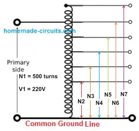
Now, suppose we want the N7 tap on the output side to produce 300 V AC, through the 220 V input AC. Therefore, we can calculate in the following simple manner:
N1/N7 = V1/V7
500/N7 = 220/300
N7 = 500 x 300 / 220 = 681 turns.
This implies that if N7 winding has 681 turn, it will produce the required 300 V, when an input of 220 V AC is applied.
Similarly if we want the winding N2 to generate a voltage say 24 V, then the number of turns this section of the tapping could be calculated using the same formula:
N1/N2 = V1/V2
500/N2 = 220/24
24 x 500 = 220 x N2
N2 = 500 x 24 / 220 = 55 turns
How to Calculate Current Rating
For calculating the current rating of the output side of an autotransformer, we must likewise know the current rating of the 220 V side winding. Let's say this is 2 amp, then the current across the N7 winding could be calculated using the following basic power formula:
V1 x I1 = V7 x I7
220 x 2 = 300 x I7
I7 = 220 x 2 / 300 = 440 / 300 = 1.46 amps.
This shows that in an auto transformer, or any type of transformer, the output wattage is ideally, almost equal to the input wattage.
How to Convert a Regular Transformer to an Autotransformer
As discussed in the previous paragraphs of this article, a regular transformer incorporates two separate winding which are electrically isolated, forming the respective primary and the secondary sides.
Since the two winding sides are electrically isolated, it becomes impossible to generate customized stepped up and stepped down AC mains voltages from these transformers, unlike an autotransformer.
However, with a small modification in the unit, a regular transformer could be to a quite an extent be converted into an autotransformer. For this we simply need to interconnect the primary side wires with the secondary side wires in s format as shown in the following diagram:
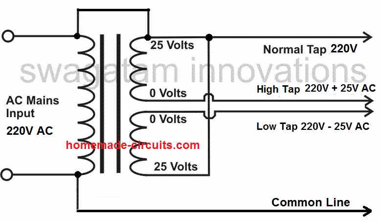
Here, we find an ordinary 25-0-25 V / 220 V step-down transformer being converted into a handy little autotransformer, simply by joining the relevant secondary/primary wires.
Once the wires the joined in the shown manner, the modified autotransformer allows the user to acquire a stepped up mains 220 + 25 = 245 AC V, or a stepped down mains of 220 - 25 = 195 AC V outputs from the relevant output wires.
hello, that’s very good for beginners many thanks
You are most welcome!
How to find turn per volt
Dear Swagatham,
Good explanantion regarding the Autotx.
Can you share the copper wire guage selection for making the Auto transformer. I am planning to rewinding a old auto transformer as I am building a 57V power supply for charging Lith Ion battery pack.
How to select the copper wire for the same. App it would be 300W power supply. IE 48V @ 6Amps.
Vijay
Thank you Vijay,
Actually I do not have the information regarding how to select the copper wire SWG for autotransformers. It seems it can be selected from an available chart or table, as done for a regular step-down transformer. You can refer to the following article and check if Table-1 could be used for this purpose or not.
https://www.homemade-circuits.com/how-to-make-transformers/
Dear Swagatam,
Would it be possible to have a circuit that uses the 60Hz 120v house power directly as an induction heater?
jr.
Dear John, it may be possible if the MOSFETs, and the inductors are appropriately calculated, which seems difficult to confirm at our level