The LM12 integrated circuit (IC)-based 100-watt amplifier circuit is a strong audio amplification solution created to produce high-quality sound in a small package.
This amplifier delivers outstanding power output while preserving a tiny footprint by using the capabilities of the LM12 IC.
Because it is a monolithic circuit, the LM12 IC is an effective and practical option for high-power amplification applications.
This permits the integration of numerous amplification functionalities onto a single chip.
Circuit Description
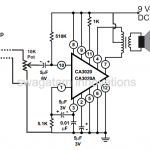
The circuit diagram shown below corresponds to an application note from the manufacturer.
The LM12 IC is a power operational amplifier, and as such, it can be wired as a 100 watt amplifier, integrator, or oscillator.
For this application note, it is wired as a non-inverting amplifier with a gain of Av=1+R3/R2=16.
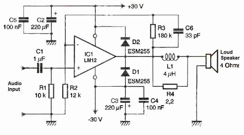
If you want to increase the gain, simply increase the value of R3 while keeping the product R3xC6 constant. In fact, R3 and C6 define the high cut-off frequency.
With the chosen values, we obtain F1=1/(2πR3C6)=26.8 kHz.
The low frequencies are limited by the R1xC1 combination, with a frequency of F2=1/(2πR1C1)=15.9 Hz.
The diodes D1 and D2 protect the output of the operational amplifier by limiting the voltage to VDD + VD and VSS - VD, which are approximately +30.5V and -30.5V, respectively.
Power Supply Circuit
We have opted for a regulated power supply at ±30V, which allows us to achieve the maximum performance of the operational amplifier.
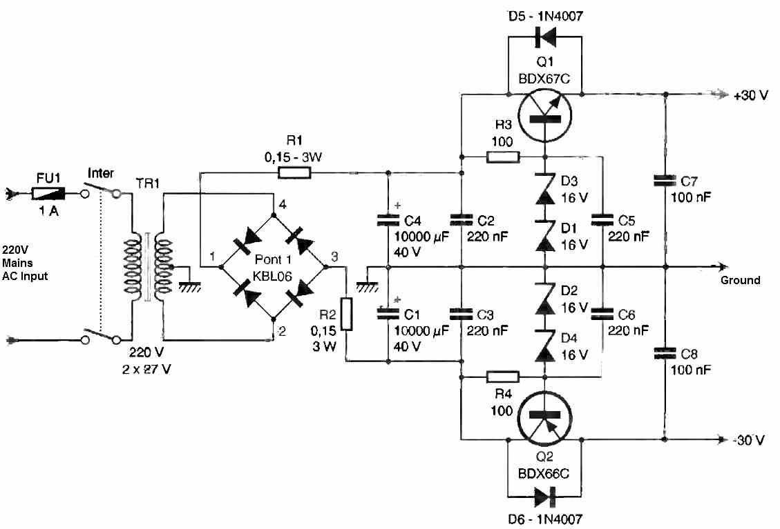
Its operation is very simple: a transformer provides two 27V AC voltages that are rectified by a diode bridge. Resistors R1 and R2 limit the current during the initial charging of the capacitors (power-on).
This yields two DC voltages of ±35V, which are then reduced to ±30V. To achieve this, we bias two transistors (Q1 and Q2) at fixed voltages, the values of which depend on the zener diodes D1 to D4.
With the chosen values, we have Vz = 32V, which gives us an output voltage of 30V (Q1 and Q2 are Darlington transistors with a variable Vbe ranging from 1.2V to 2V depending on the value of the current Ic).
As for diodes D5 and D6, they protect the transistors from negative Vce voltages (power-off). The component values are given for the power supply of a single amplifier module.
If you wish to build a stereo amplifier, it is advisable to double the value of C1 and C4 and increase the power rating of the transformer to 300VA. If feasible, it is preferable to create two independent power supplies, one for each channel.
Construction
In the case of a "boosted" power supply to supply power to 2 modules, the currents involved are too high to use a PCB circuit, so it is strongly recommended to create a flying wiring with appropriately sized wire (S>1.5mm2).
Capacitors such as FIRS or TFRS with screw terminals and a bridge rectifier with low losses can be chosen.
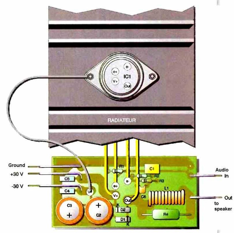
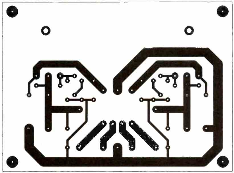
Both PCB circuits are relatively easy to create, whether using a direct etching method or a photographic method.
For the amplifier module, the PCB is inserted into the heat sink - slots are provided for this purpose - and it is important to measure the available space accurately.
A heatsink model with a thermal resistance below 0.9°C/W should be chosen. For example, a 10cm type CO2044P (SEEM) or P2327 (Selectronic) or KL125 (Seifert Electronic) or WA508 (Schaffner) can be used.
As for the heat sink supporting the power transistors, a model with Rth < 2°C/W should be selected (for example, 10cm of S53), or Rth < 1°C/W if powering 2 modules (P2327 or 25cm of S53...).
To connect the LM12 IC to the PCB, we used small pieces of single-strand wire with a section of 1.5mm2, which we soldered and insulated with heat shrink tubing.
To obtain L1, we recommend winding around ten turns of enameled 1.5mm2 wire on a 5mm or 6mm drill.
Setup and Testing
Before powering on the amplifier, it is necessary to verify that the pins of the LM12 IC are properly isolated from the heat sink and that the diodes and capacitors are correctly installed. No adjustments are required; the amplifier is ready to operate.
With 4 Ω speakers, we achieve high-quality sound and impressive power. We have measured the following technical specifications:
- Output Power: 100 W / 4 Ω, 50 W / 8 Ω
- Bandwidth: 17 Hz to 26 kHz
- Distortion: 0.01% Input
- Sensitivity: 1.25 Vrms for maximum power (Pmax)
- Input Impedance: 10K ohms


Questions & Answers
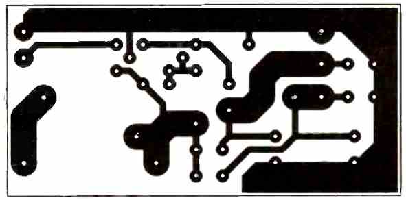
I would like you to show the top silkscreen of the power supply board.
Thank you.
Exactly it’s as you say, as far as the transformer is concerned, the rectifier and the capacitors. The problem is at the output of the transistors – if they’re able to keep the voltage as constant as there are those bass hits.And if we put the big-capacity capacitors at the output of the transistors, is there a chance that they will burn out?
The 10,000uF capacitors are big enough to keep the amplifier working even with high bass…but obviously the transformer current rating must be also big enough.
Hi,
congratulations on what you do.
As for the power supply of this amplifier – isn’t it that as soon as there’s a big bass hit – the power supply gives out ?
Waiting for your response – kind regards.
Hey, you are right, and to compensate the high bass levels, the power supply must be rated sufficiently, so that even at high bass levels the voltage does not drop…