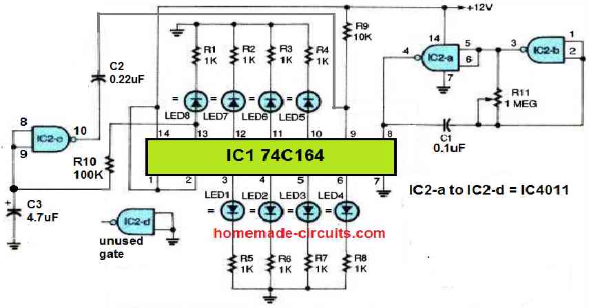
Referring to the following chaser circuit diagram below, we can see a low-frequency, astable oscillator circuit, made up of two gates, IC1a and IC1b, from the IC 4011 quad two-input NAND gate. The operating frequency of this astable is determined by the values of C1 and R11. This circuit configuration works well as a clock-pulse […]