This delay off lamp timer circuit will automatically switch OFF a connected lamp after a predetermined time has elapsed. This time delay can be adjusted with a variable resistor or a potentiometer.
The circuit is initiated by pressing a push button, which causes the connected lamp to switch ON.
The lamp will continue to remain ON until the predetermined delay has elapsed and then the lamp will switch OFF automatically.
This delay off lamp timer circuit has one great inherent feature.
The lamp becomes dim and its brightness decreases as soon as the switch OFF threshold is reached. This allows the user to know that the delay OFF time is about to expire and the lamp is about to shut off.
Therefore, in this situation, if required, the user can press the start button once again to refresh the delay time and allow the timer to continue to illuminate the lamp for next timing cycle.
The installation is very simple and given its dimensions, it can be placed in a wall box typically used for electricity.
Introduction
The timing is achieved thanks to a high value capacitor charged through a resistance whose value is adjustable in order to calibrate the lighting duration.
The timing is between 20 seconds and 2 minutes. The exponential evolution of the voltage at the timing capacitor terminals is then compared to a voltage threshold determining the end of the lighting duration.
The extinction warning is achieved thanks to the particular behavior of the low voltage supply of the circuit.
In fact, this supply is directly derived from the mains voltage. In fact, its very simple design gives it limited characteristics which are exploited by our circuit to reduce the lighting at the end of the timing.
Circuit Diagram
Figure 1 below shows the diagram of the timer, which consists of direct power supply from the mains, a timing comparator, and a power stage with a triac.
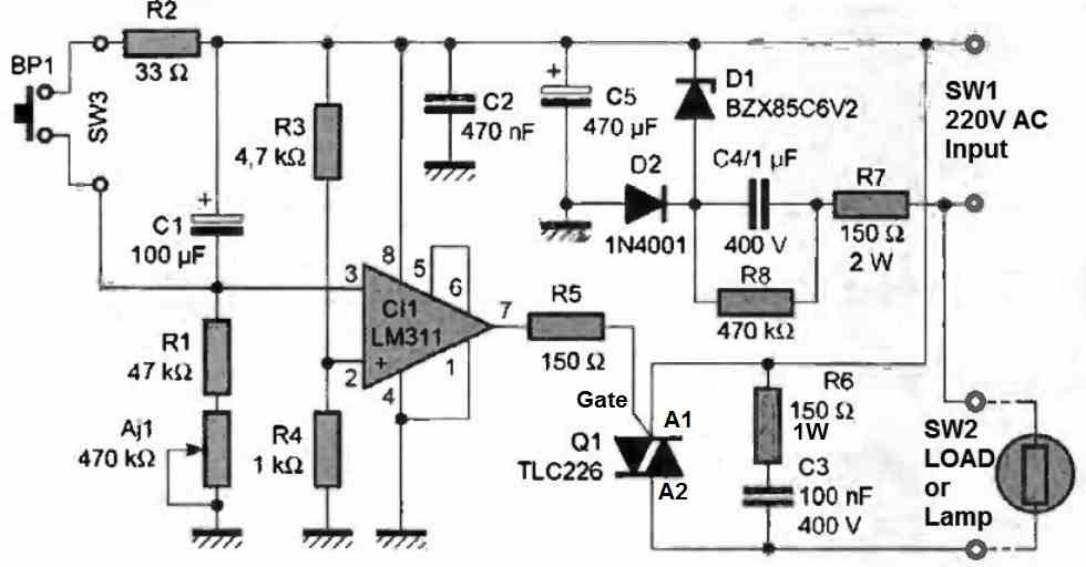
The power supply The current in the zener diode is limited by the impedance 1/C.o) of capacitor C4.
The use of a capacitor to produce a voltage drop is interesting because the dissipated power is zero.
Indeed, a capacitor is a purely reactive element (90° phase shift between the voltage across it and the current that flows through it).
At the mains frequency, which is 50 Hz, the impedance of capacitor C4 is 3,200 Ω.
At power-up, the current in zener diode D1 is limited by fuse resistor R7.
Diode D2 performs a half-wave rectification and charges capacitor C5 to the zener voltage of diode D1, minus the direct voltage drop of diode D2, which is Vz - 0.7 V.
Between two mains cycles, the consumption of the circuit slightly discharges capacitor C5, so that a residual ripple exists across it.
This ripple does not disturb the operation of the comparator and can therefore be exploited to trigger the extinction warning.
The timer Comparator C11 compares the voltage across capacitor C1 with the threshold determined by the R3/R4 resistor bridge.
The output of comparator C11 is intended to drain the trigger current causing the triac to trigger and light up the lamp.
As a reminder, the output stage of an LM311 consists of an open-collector transistor capable of accepting a maximum current of 50 mA.
The timer is triggered by the push button BP1, which almost instantaneously discharges capacitor C1 into the low-value resistor R2.
From this moment on, capacitor C1 begins to charge through the R1+Aj1 resistor: at the beginning of its charge, the input (e-) of the comparator is close to 5 V.
Since its input (e+) is set to a little less than 1 V by the R3/R4 voltage divider, its output 7 is in the low state.
As long as the output of C11 is in the low state, current flows through the triac trigger circuit, which is then triggered at the beginning of each mains cycle.
The triac then behaves like a closed switch and the lamp is turned on.
The warning period
The capacitor C1's charge gradually brings the input (e-) to the potential of the input (e+).
However, the threshold set by the voltage divider R3/R4 is subject to ripple due to the characteristics of the previously mentioned power supply voltage.
Thus, when the voltages of the two inputs (e+) and (e-) are close to each other, one will sometimes be higher and sometimes lower than the other, due to the ripple present at the node of the voltage divider R3/R4.
There will therefore be repeated switching of the switch output according to the evolution of the ripple over time.
In fact, the triac will be triggered on every other half-cycle of the mains voltage. The brightness of the lamp will thus be reduced, to allow the user to be warned of the timer's impending end.
During this warning phase, the user can take the precaution of pressing the pushbutton BP1 again to restart the timer, without having to feel along the walls because the brightness will still be sufficient.
Implementation
Figure 2 below provides a trace of the tracks for this timer, and also the component placement.
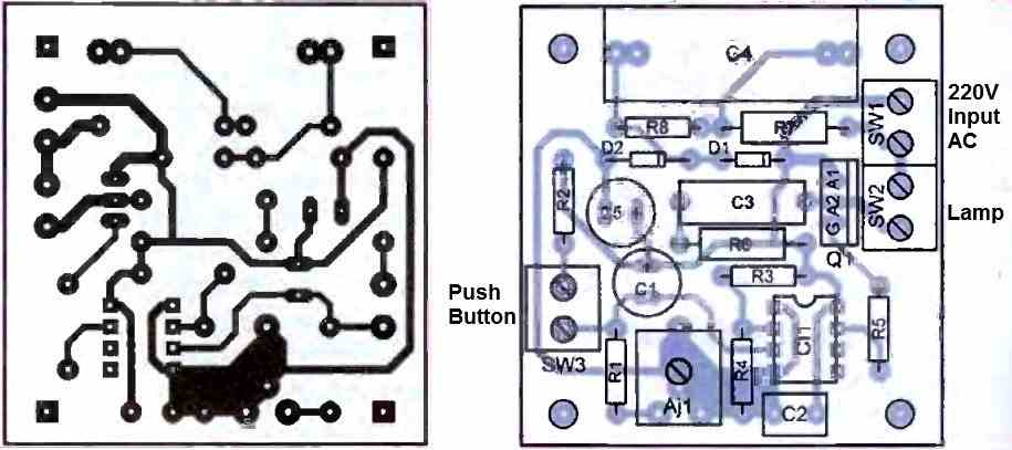
Use an adjustable resistor Aj1 in a plastic casing to avoid any risk with the mains when recalibrating the timer.
The overall implementation presents very few difficulties and the assembly should function as soon as it is powered up.
If you have taken care to connect a 220 V filament lamp to the SW2 output, it should light up as soon as the mains are connected, without the need to press the pushbutton, since the capacitor C1 is then discharged.
At the end of the timing period, which is set by Aj1, the lamp should turn off, after a warning phase (lower illumination). Press the pushbutton to restart the timer, and the lamp should immediately light up fully.
If these tests are successful, you can permanently install your timer within your installation.
The room switch will then be replaced with a similar module in push-button version. It is not necessary to equip the triac with a heat sink to control a simple light bulb.
Moreover, TO-220 package models can control a maximum power bulb of 200 W without a heat sink.
Depending on the sensitivity of the triac, the value of resistor R5 can be modified. For a value of 150 ohms, the gate current will be about 25 mA.
The maximum duration of the timer can be doubled and reach four minutes with an adjustable resistor Aj1 of 1 MΩ instead of 470 kΩ. For a shorter timer duration, you can double the duration of the extinction warning by reducing the value of capacitor C5 from 470 pF to 220 pF.

Need Help? Please Leave a Comment! We value your input—Kindly keep it relevant to the above topic!