In this post I have explained 2 easy to build induction heater circuits which work with high frequency magnetic induction principles for generating substantial magnitude of heat over a small specified radius.
The discussed induction cooker circuits are truly simple and uses just a few active and passive ordinary components for the required actions.
Update: You may also want to learn how to design your own customized induction heater cooktop:
Designing an Induction Heater Circuit - Tutorial
Induction Heater Working Principle
An induction heater is a device that uses a high frequency magnetic field to heat up an iron load or any ferromagnetic metal through eddy current.
During this process electrons inside iron are unable to move as fast as the frequency, and this gives rise to a reverse current in the metal termed as eddy current. This development of high eddy current ultimately causes the iron to heat up.
The generated heat is proportional to current2 x resistance of the metal. Since the load metal is supposed to be made up of iron, we consider the resistance R for the metal iron.
Heat = I2 x R (Iron)
Resistivity of Iron is: 97 nΩ·m
The above heat is also directly proportional to the induced frequency and that's why ordinary iron stamped transformers are not used in high frequency switching applications, instead ferrite materials are used as cores.
However here the above drawback is exploited for acquiring heat from high frequency magnetic induction.
Referring to the proposed induction heater circuits below, we find the concept utilizing the ZVS or zero voltage switching technology for the required triggering of the MOSFETs.
The technology ensures minimum heating of the devices making the operation very efficient and effective.
Further to add, the circuit being self resonant by nature automatically gets sets at the resonant frequency of the attached coil and capacitor quite identical to a tank circuit.
Using Royer Oscillator
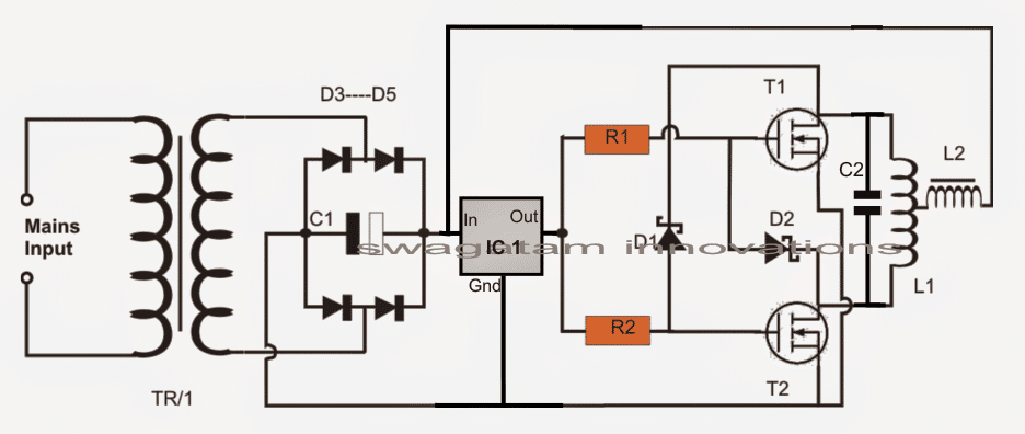
The circuit fundamentally makes use of a Royer oscillator which is marked by simplicity and self-resonant operating principle.
The functioning of the circuit could be understood with the following points:
- When power is switched ON, positive current begins flowing from the two halves of the work coil towards the drains of the mosfets.
- At the same the supply voltage also reaches the gates of the mosfets turning them ON.
- However due to the fact that no two mosfets or any electronic devices can have exactly similar conducting specifications, both mosfets do not turn on together, rather one of them turns ON first.
- Let's imagine T1 turns ON first. When this happens, due to heavy current flowing through T1, its drain voltage tends to drop to zero, which in turn sucks out the gate voltage of the other mosfet T2 via the attached schottky diode.
- Here, it may seem that T1 might continue to conduct and destroy itself.
- However, this is the moment when the L1C1 tank circuit comes into action and plays a crucial part. The sudden conduction of T1 causes a sine pulse to spike and collapse at the drain of T2. When the sine pulse collapses, it dries down the gate voltage of T1, and shuts it down. This results in a rise in voltage at the drain of T1, which allows a gate voltage to restore for T2. Now, its the turn of T2 to conduct, T2 now conducts, triggering a similar kind of repetition that occurred for T1.
- This cycle now continues rapidly causing the circuit to oscillate at the resonant frequency of the LC tank circuit. The resonance automatically adjusts to an optimal point depending on how well the LC values are matched.
However the main downside of the design is that it employs a center tapped coil as the transformer, which makes the winding implementation a bit trickier. However the center tap allows an efficient push pull effect over the coil through just a couple of active devices such as mosfets.
As can be seen, there are fast recovery or high speed switching diodes connected across the gate/source of each mosfet.
These diodes perform the important function of discharging the gate capacitance of the respective mosfets during their non-conducting states thereby making the switching operation snappy and quick.
How ZVS Works
As I have explained earlier, this induction heater circuit works using the ZVS technology.
ZVS stands for zero voltage switching, meaning, the mosfets in the circuit switch ON when they have minimum or amount of current or zero current at their drains, we have already learned this from the above explanation.
This actually helps the mosfets to switch ON safely and thus this feature becomes very advantageous for the devices.
This feature could be compared with the zero crossing conduction for triacs in AC mains circuits.
Due to this property the mosfets in ZVS self resonant circuits such as this require much smaller heatsinks and can work even with massive loads upto 1 kva.
Being resonant by nature, the frequency of the circuit is directly dependent on the inductance of the work coil L1 and the capacitor C1.
The Frequency could be calculated using the following formula:
f = 1 / ( 2π * √[L * C] )
Where f is the frequency, calculated in Hertz
L is the inductance of the Main Heating Coil L1, presented in Henries
and C is the capacitance of the capacitor C1 in Farads
Solving a Practical Example:
If the tank circuit consists of:
- Lt = 10 µH (Inductor)
- Ct = 0.1 µF (Capacitor)
The resonant frequency is:
f = 1 / (2 * π * √(Lt * Ct))Substitute the values:
f = 1 / (2 * π * √(10 x 10-6 * 0.1 x 10-6))

Simplify:
f = 1 / (2 * π * √(1 x 10-12))f = 1 / (2 * π * 10-6)
f ≈ 159.15 kHzImportant Notes:
You may find that the actual operating frequency may deviate slightly due to:
- Non-ideal values in the components (e.g. parasitic resistance in the capacitors or MOSFETs).
- Loads variations (for e.g. placing a metal object in the work coil alters the Lt).
- The influence of the current-limiting inductors.
The circuit will lock onto the resonant frequency automatically through the ZVS feedback mechanism ensuring an efficient operation.
For precise design you must measure the inductance (Lt) and capacitance (Ct) using an LCR meter, or adjust the capacitor bank, to fine tune the frequency.
The MOSFETs
You can use IRF540 as the mosfets which are rated at good 110V, 33amps. Heatsinks could be used for them, although the heat generated is not to any worrying level, yet still it's better to reinforce them on heat absorbing metals. However any other appropriately rated N channel MOSFETs can be used, there are no specific restrictions for this.
The inductor or inductors associated with the main heater coil (work coil) is a kind of choke that helps eliminating any possible entry of the high frequency content into the power supply and also for restricting the current to safe limits.
The value of this inductor should be much higher compared to the work coil. A 2mH is generally quite enough for the purpose. However it must be built using high gauge wires for facilitating a high current range through it safely.
The Tank Circuit
C1 and L1 constitute the tank circuit here for the intended high resonant frequency latching. Again these too musts be rated to withstand high magnitudes of current and heat.
Here we can see the incorporation of a 330nF/400V metalized PP capacitors.
1) Powerful Induction Heater using a Mazzilli Driver Concept
The first design I have explained below is a highly efficient ZVS induction concept based on the popular Mazilli driver theory.
It uses a single work coil and a two current limiter coils. The configuration avoids the need of a center tap from the main work coil thus making the system extremely effective and rapid heating of load with formidable dimensions. The heating coil heats the load through a full bridge push pull action
The module is actually available online and can be easily bought at a very reasonable cost.
The circuit diagram for this design can be seen below:
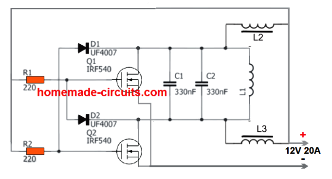
The original diagram can be witnessed in the following image:
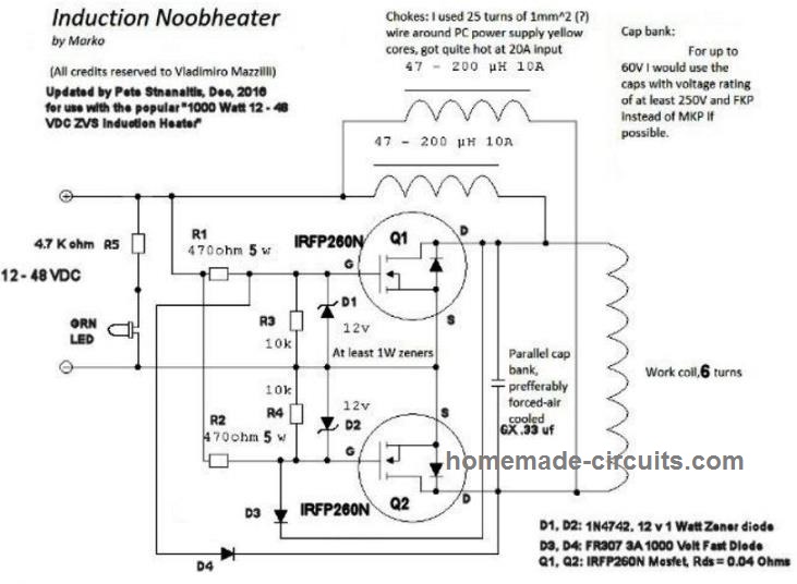
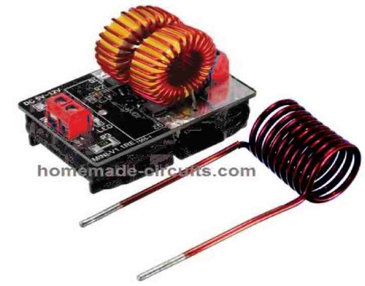
The working principle is the same ZVS technology, using two high power MOSFETs. The supply input can be anything between 5V and 12V, and current from 5 amps to 20 amps depending on the load used.
Power Output
The power output from the above design can be as high as 1200 watts, when the input voltage is raised up to 48V, and current up to 25 amps.
At this level the heat generated from the work coil can be high enough to melt a 1 cm thick bolt within a minute.
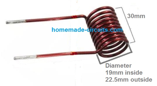
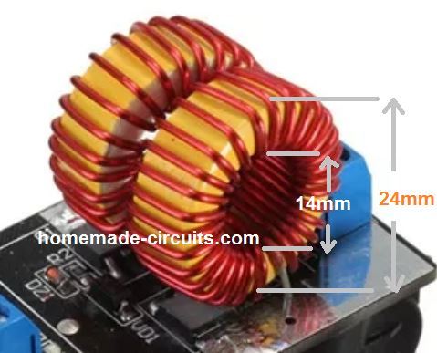
Work Coil Dimensions
Video Demo
2) Induction Heater using a Center Tap Work Coil
This second concept is also a ZVS induction heater, but uses a center bifurcation for the work coil, which may be slightly less efficient compared to the previous design.
The L1, which is the most crucial element of the whole circuit. It must be built using extremely thick copper wires so that it sustains the high temperatures during the induction operations.
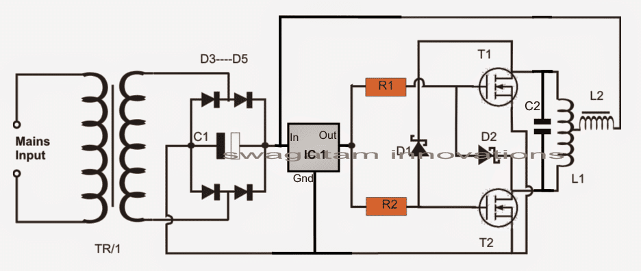
The capacitor as discussed above must be ideally connected as close as possible to the L1 terminals. his is important for sustaining the resonant frequency at the specified 200kHz frequency.
Primary Work Coil Specifications
For the induction heater coil L1, many 1mm copper wire may be wound in parallel or in bifilar manner in order to dissipate current more effectively causing lower heat generation in the coil.
Even after this the coil could be subjected to extreme heats, and could get deformed due to it therefore an alternative method of winding it may be tried.
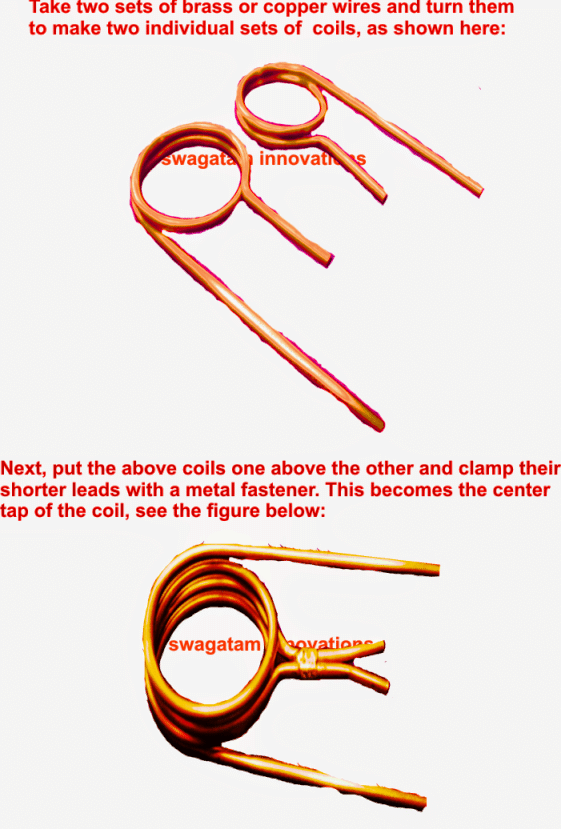
In this method we wind it in the form of two separate coils joined at the center for acquiring the required center tap.
In this method lesser turns may be tried for reducing the impedance of the coil and in turn increase its current handling capability.
The capacitance for this arrangement may be in contrast increased in order to pull down the resonant frequency proportionately.
Tank Capacitors:
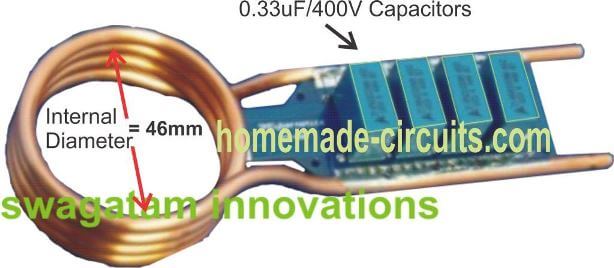
In all 330nF x 6 could be used for acquiring a net 2uF capacitance approximately.
How to Attach Capacitor to the Induction Work Coil
The following image shows the precise method of attaching the capacitors in parallel with the end termianals of the copper coil, preferably through a well dimensioned PCB.
Parts list for the above induction heater circuit or induction hot plate circuit
- R1, R2 = 330 ohms 1/2 watt
- D1, D2 = FR107 or BA159
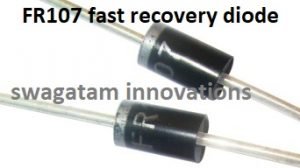
- T1, T2 = IRF540
- C1 = 10,000uF/25V
- C2 = 2uF/400V made by attaching the below shown 6nos 330nF/400V caps in parallel
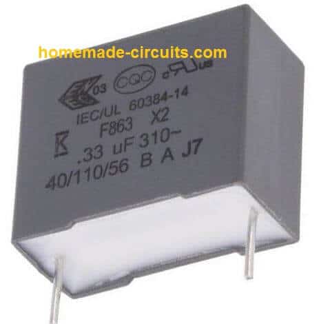
- D3----D6 = 25 amp diodes
- IC1 = 7812
- L1 = 2mm brass pipe wound as shown in the following pics, the diameter can be anywhere near 30mm (internal diameter of the coils)
- L2 = 2mH choke made by winding 2mm magnet wire on any suitable ferrite rod
- TR1 = 0-15V/20amps
- POWER SUPPLY: Use regulated 15V 20 amp DC power supply.
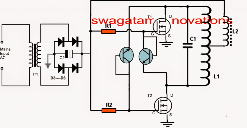
Using BC547 transistors in place of high speed diodes
In the above induction heater circuit diagram we can see the MOSFETs gates consisting of fast recovery diodes, which might be difficult to obtain in some parts of the country.
A simple alternative to this may be in the form of BC547 transistors connected instead of the diodes as shown in the following diagarm.
The transistors would perform the same function as the diodes since the BC547 can operate well around 1Mhz frequencies.
Another Simple DIY Design
The following schematic shows another simple design, similar to the above, which can be constructed quickly at home for implementing a personal induction heating system.
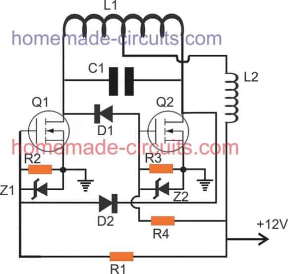
Parts List
- R1, R4 = 1K 1/4 watt MFR 1%
- R2, R3 = 10K 1/4 watt MFR 1%
- D1, D2 = BA159 or FR107
- Z1, Z2 = 12V, 1/2 watt zener diodes
- Q1, Q2 = IRFZ44n mosfet on heatsink
- C1 = 0.33uF/400V or 3 nos 0.1uF/400V in parallel
- L1, L2, as shown in the following images:
- L2 is salvaged from any old ATX computer power supply.
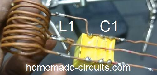
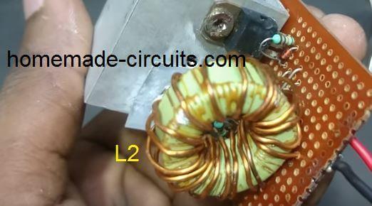
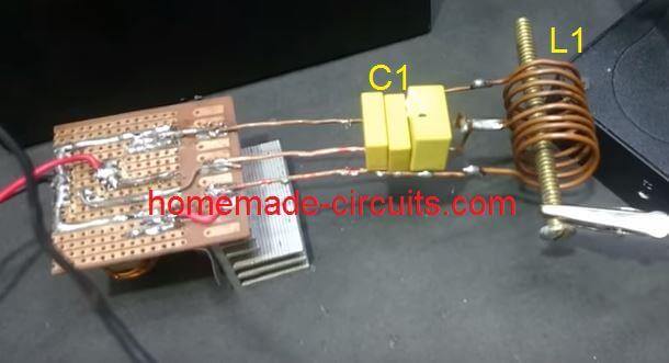
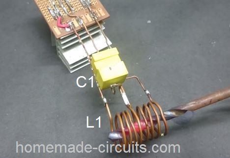
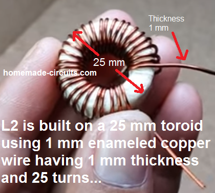
How L2 is Built
Modifying into a Hot Plate Cookware
The above sections helped us to learn a simple induction heater circuit using a spring like coil, however this coil cannot be used for cooking food, and needs some serious modifications.
The following section of the article explains, how the above idea can be modified and used like a simple small induction cookware heater circuit or an induction kadai circuit.
The design is a low tech, low power design, and may not be on par with the conventional units. The circuit was requested by Mr. Dipesh Gupta
Technical Specifications
Sir,
I have read ur article Simple Induction Heater Circuit - Hot Plate Cooker Circuit And was very happy to find that there are people ready to help youngsters like us to do something ....
Sir I am trying to understand the working and trying to develop an induction kadai for myself ... Sir please help me understanding the designing as I m nt so good in electronics
I want to develop an induction to heat up a kadai of dia 20 inch with 10khz frequency at a very low cost !!!
I saw your diagrams and article but was a bit confused about
- 1. Transformer used
- 2. How to make L2
- 3. And any other changes in the circuit for 10 to 20 kHz frequency with 25ams current
Please help me sir as soon as possible ..It will be help full if u could provide with the exact components detail needed .. PlzzAnd lastly u had mentioned to use POWER SUPPLY: Use regulated 15V 20 amp DC power supply. Where is it used ....
Thanks
Dipesh gupta
The Design
The proposed induction kadai circuit design presented here is just for experimental purpose and may not serve like the conventional units. It may be used for making a cup of tea or cooking an omelet quickly and nothing more should be expected.
The referred circuit was originally designed for heating iron rod like objects such as a bolt head. a screwdriver metal etc, however with some modification the same circuit can be applied for heating metal pans or vessels with convex base like a "kadai".
For implementing the above, the original circuit wouldn't need any modification, except the main working coil which will need to be tweaked a bit to form a flat spiral instead of the spring like arrangement.
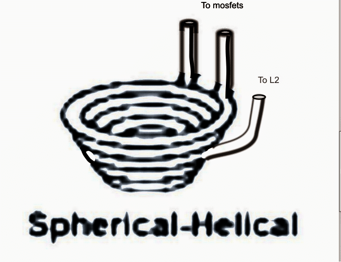
As an example, in order to convert the design into an induction cookware so that it supports vessels having a convex bottom such as a kadai, the coil must be fabricated into a spherical-helical shape as given in the figure below :
The schematic would be the same as explained in my above sevction, which is basically a Royer based design, as shown here:
Designing the Helical Work Coil
L1 is made by using 5 to 6 turns of 8mm copper tube into a spherical-helical shape as shown above in order to accommodate a small steel bowl in the middle.
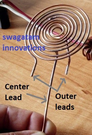
The coil may be also compressed flat into a spiral form if a small steel pan is intended to be used as the cookware as shown below:

Designing the Current Limiter Coil
L2 may be built by winding a 3mm thick super enameled copper wire over a thick ferrite rod, the number of turns must be experimented until a 2mH value is achieved across its terminals.
TR1 could be a 20V 30amp transformer or an SMPS power supply.
The actual induction heater circuit is quite basic with its design and does not need much of an explanation, the few things that needs to be taken care of are as follows:
The resonance capacitor must be relatively closer to the main working coil L1 and should be made by connecting around 10nos of 0.22uF/400V in parallel. The capacitors must be strictly non-polar and metalized polyester type.
Although the design may look quite straightforward, finding the center tap within the spirally wound design could pose some headache because a spiral coil would have an unsymmetrical layout making it difficult to locate the exact center tap for the circuit.
It could be done by some trial and error or by using an LC meter.
A wrongly located center tap could force the circuit to function abnormally or producing unequal heating of the mosfets, or the entire circuit may just fail to oscillate under a worst situation.
Reference: Wikipedia



Questions & Answers
Dear sir which diode can i put in place of FR107
You can use BC547 transistor in place of the diodes. Connect base and collector together with the gate of the mosfet, and emitter to the drain of the other mosfet. Remember this is only a suggestion…
No, only the specified type will work.
Hello sir can I use it for boiling a moving water from pipe.
Helo Salman,
Yes you can do it, but the pipe should be made of iron or steel (magnetic material)
Thank you for the quick response,
So pipe that Water flow inside, is a metal to be heated or as a induction metal(L1)?
The iron water pipe should pass through the center of the coil L1 as shown in the last diagram.
Not worked swgtm. the material not even heat up & both mosfets burnt out. it specified 200kHz frequency. So can i use Astable multivibrator to set frequency 200Khz to drive the coils.
Hi Max,
What did you use for D1/D2 and L2?
FR302 & 40 turns on a ferrite bead as L2
hello swagatam.
Plz suggest a circuit to run cooling fan externally. i bought a amplifier unit the heat sense fan stops automatically after 1 minute. need a solid state cheap circuit to run fan directly from mains. (fan rated 12vdc 0.25amp 2.5w)
Hello Max,
The only solution is to a use a readymade 12V ac/dc smps adapter rated at 500mA or 1amp current, because you won't get below this rating.
Hello Swagatam,
I have built my one successfully with DC power source of 18V connected to L2 while the other side keep 12V to drive MOSFET. I am also connecting ammerter in series to L2 to monitor the current. With some bolts and nuts or steel rod. They can turn red hot without problem. Current goes up from original L1 coil without anything inside to some level according to the object inside the coil. Somehow, I try this with 1/2" diameter steel pipe with 0.5mm thickness. Current goes up and increasing. After a while when pipe is in red hot, current suddenly increase very rapidly and FET burn-out. At this point, everything stop. I have to change FET as it was shorted Drain-Source. I used IRFP250N and diode BYV26E, pretty high rated voltage and current but still failed. Do you have any idea what I did wrong? Is this due to FET or Diode? Thanks.
Helo Sitti,
Try the following circuit, set Rt, Ct for getting 200khz, use L2 in place of "L" and the L1 for RL.
https://www.homemade-circuits.com/2013/09/half-bridge-mosfet-driver-ic-irs21531d.html
This circuit will never allow your mosfets to blow off, according to me.
link is not available
please use this one instead
https://www.homemade-circuits.com/2013/09/half-bridge-mosfet-driver-ic-irs21531d.html
Is there any alternative power supply? Cause its too expensive to buy a 20 A transformer then make it DC supply. By the way, could I use a power supply with adjuster in order to control the temparature of the induction coil?
sorry there's no direct alternative for high current. You can reduce it proportionately by increasing the voltage, but that would also require modifications in the work coil, the turns will need to be increased while the gauge will need to reduced accordingly.
thanks for the quick reply, I really want to learn more about induction heating. Where I can find a choke coil required L2 because I can't find one of it in some electronics store here in my place, is it okay not to put L2? I want to share my idea to you, I have a circuit design that I found in the internet to control temperature, how can I share it to you?
You won't get the coils readymade, you will have to hand make it as per the details shown in the images and the article info.
You are welcome to share your ideas, please send it to hitman2008@live.in
is it safe that my transformer that is rated 6A only is giving me up to 10A of current. Because i connected it to a bridge rectifier and a 4700uF caps to make a dc power supply, then i successfully make the circuit work but when I measured the current flowing to the transformer using a clamp meter, it gives me up to 10A depending on the metal to be heated. is it still safe for the transformer producing greater current than its rating?
if it's showing more than the specified amps of the transformer means the voltage is being dropped proportionately in the course….so ultimately the total power is never being exceeded.
as far as the above circuit is concerned, the coil would handle current depending upon its thickness, if it's correctly dimensioned it would be safe.
sir supply is 300w or 15v 20a ?
It's 15V/20amp, that's equal to 300 watts
sir, i mean can i use 150v 2amp?
no, it should be @15V, amps is not important can be of any value (not less than 20amps)
Sir, both terminal will be +ve? if yes then; where is -ve terminal? And in MOSFET source will be grounded or -ve?
only the mosfet sources will go to the negative of the supply, no other point of the circuit is connected to the supply negative.
Sir, this kind of power supply(15v, 20a)is not esily available in the market.So, at which minimum voltage and current the circuit will be run?
Vinay, you can use a 12V, 20 amp transformer
Hello Swatam
what changes I should make in the circuit to operate at 220V , two phases, each 110 V and a power of 6kW.
and I'm thinking to cool L1 and L2 with water that circulates inside
this is possible.
Hello Paul,
Sorry, I think that may not be recommended and could require more number of turns for L1/L2…I do not have the data for calculating those.
thank you very much.
the number of turns can prove, but the electronic elements can recommend me what changes should be do.
The configuration will remain as is. The resistors could be increased to 1K 10 watt (wirewound) each, everything will need to be done through trial and error, though.
For the mosfets you can use IRF840, however since mains voltage is involved, the risks of an untoward could be on the cards, I am not recommending use of 220V for this project.
i have built one successfully but my capacitors tanks become very hot….
i am using parallel cap at single point and where the all cap meet(at single point) they get very hot.
should i mount capacitors on pipes at some distance?
yes preferably the caps must be p;aced slightly away from the coil, may be a 6 inches distance will do.
One more thing
At the start current go up very high without anything inside..
you can use a 1000 watt halogen lamp in series with the mains input to the transformer, this will ensure that the initial amp intake does not exceed to dangerous levels.
Thanks Swagatam
I made my induction heater successfully now i want to increase its power..
Can i increase power of this induction heater using more mosfets in parallel?
Please scheme a circuit for parallel combination.
Thanks
Thanks Waqar, to increase power you may try increasing the input current and also the voltage, and upgrade the mosfet with other higher rated ones, parallel combination may not be recommended.
You can select an appropriate mosfet pair from the following article
easydatasheets.blogspot.in/p/mosfets.html
Can i pass the iron or steel tube(from which water which is to be heated) three to four times from the coil L1.
it should be a copper coil, iron will not do.
k.
thanks sir
sir we are making induction heater ckt for academic project purpose so could u tell us about the length and turns of L1,L2
you can find it in this video: https://www.youtube.com/watch?v=pVYMLnXW9uo
can i use a high rated transformer and then minimize the current and voltage by a rheostat.
you may have to do it through a variac, a rheostat will not do.
ty sir.
can i fed the circuit with directly 20 amp or i have to increase it gradually because the insulation of my wire which are use for connection are burning along with mosfet.
what is the reason for the same
increase it gradually, but if the mosfets are also burning it means the circuit is malfunctioning and there could be a fault in the circuit
sir plz help me out.
when i increase the voltage with the variac my bridge rectifier burned out at 7 volt and if i fed the circuit directly my mosfet burned out.
what should i do..
Pratik, it means the circuit is drawing huge currents without load, something is incorrect in your circuit.
try a bridge driver type of circuit instead of the above self resonanat design for reliable results
Hello sir,
Can we control the temperature of this circuit and can we use small lcd for viewing temperature.
K..
I'LL CHECK IT OUT
Dear Swagatam, thank you very much for the details of the construction of this circuit. I built the heater and works well. I have a question related to the possibility to change the frequency of the system. I need differents frequencies. And I am thinking of if possible to change Capacitor and L at the same time to get any frequency. This is possible? Like for example 200Khz , 300 Khz, 400 and soon.
Also I would know how I can calculate the magnetic intensity of the system.
Thank you very much.
Thanks Guillermo, the above circuit is a self resonant type of configuration so frequency cannot be changed manually….you may have to incorporate an external oscillator circuit for implementing an adjustable resonance, the following half bridge circuit could tried with the coil network explained in the above article for achieving the same:
https://www.homemade-circuits.com/2013/09/half-bridge-mosfet-driver-ic-irs21531d.html
Thank You again, i will try the this circuit and let You knoe my progress. Cheers
dear sir I have a old induction heater coil . i want to use that coil . how can i use that coil for heat the panel. please tell me with using simple words. thank you…,…
Dear Kamaljeet, without seeing the coil it would be difficult to suggest anything, anyway a commercial induction coil will require a sophisticated circuitry, much complex than the above published design…
sir
L1 copper wire gauge # kia hay
L1 should be preferably a copper pipe having a outer diameter of about 1cm, using a pipe will enable water to be circulated through it in order to keep the coil temp within limits
thanks sir for reply.
kia ma ap ko urdu ma b question kr sakta hun
yes, but my replies will be in English.
hello
what is the exact use of transformer? it is impedance matching only? what can we use instead of transformer
which transformer…TR1?
It's for supplying power to the circuit.
Hello sir,
what power has to be given to heat a coil?
hello jayalaxmi,
the power specs are approximately 20V 15amps
Sir,
Cant we heat the coil with Dc source using driver circuit??
I did an oscillator circuit of a supply of 24Vdc and 0.3A and got an output of 46MHz and 19v as peak to peak voltage.
Can we heat the coil with that frequency ?? what are the possible ways??
Jayalaxmi, the coil is not supposed to heat, the vessel is supposed to get hot.
0.3A will not produce any result…it should be at least 10 to 15 ampere
Hi there,
Its a very nice technology. Thanks for the circuit.
What is the value of L1 and can i use pan cake coil of the same inductance?
The inductance value is not crucial, you can make it as per the given instructions in the diagram, yes with little modifications it can be converted for the pan type implementation.
Hey, great thread. I was wondering what changes would need to be made to the schematic and the induction coil to work using 3.7vdc max 30amp load. This would obviously be used in a micro induction coil to heat small objects such as a sewing needle. And suggestion on coil size, wrapping and component change on the schematic would be greatly appreciated.
Thanks!
Dan
thanks Dan, I think it may have to be done through some trial and error since I do not have a formula for calculating the coil.
The only thing I know is that as the turns increase and the diameter decrease the operating frequency and the current consumption also decrease proportionately, so on this basis you could probably do some experimentation.
L2 and the other components except the voltage may not require a change as per my knowledge
hi sir…we try the circuit using the power supply of the computer as the power supply to the circuit….in our first try….the metal that we put on the middle of the working coil gets hot….but the mosfets gets hot too…..so we decided to change the heatsink with bigger one……after changing we try it again…….and the metal dont get hot……why is it happen sir??thanks for the reply
Hi Christian, I guess this could be related to some frequency variations due to the introduction/removel of the metal plate.
heating up of the msgfets might be hampering the generation of the resonance frequency which might be getting corrected with the addition of the larger hetasink and resulting in an automatic correction of the frequency.
Not sure though, this could be the reason.
by the way you are not supposed to put a metal inside the working coil, this might seriously affect the functioning of the circuit
but, is it ok that we use a power supply of a computer as the supply for this circuit?
what could you suggest sir for us to make this induction warmer work.?
I'm sorry sir… the metal that we put inside the working is a screw driver just to test if it is working already,if the working coil produce induction heat
.
oh… that was quite silly of me, I completely forgot that a metal (magnetic) needs to be inserted inside the work coil for implementing the design, make sure the heatsinks are perfectly aloof and are not touching anything in the circuit….
any power supply will do as long as it's able to generate 15 to 20 amps for the circuit.
good day sir…..in the 2 small diagram above…..the c1 and c2 are in different position…which capacitor do we need to parallel in the l1?
we use a power supply of a computer….if we use the bridge driver type circuit…do we still needed to parallel a capacitor with the + and – of the power supply??
C1 value needs to be arranged by putting many MKT capacitors in parallel.
If you are using a pure DC from an SMPS in that case C2 can be eliminated….
….I am referring to C1 which is in parallel with L1, and C2 at the bridge…
sir may iuse it to cooking purpose
It won't be possible with the shown coil dimension
am working on this circuit from last few weeks but its not working as i expect it too. am using a coil of 12 gauge 9 turns center taped mosfet irfz44n ,22uf 4 caps in parallel adn the voltage suply is 15 v 12 amps its from a transformer ( battery charger) as i turn on the circuit the the mosfets blows up within seconds seeps like shor circuted help pe am not using any choke .
am working on this circuit from few weeks and am facing the same proble as soon as i turn on the supply the current increses upto 40-70 amps and the mosfets blows up . am using irfz44n and 17v 10 amps power supplt from a transformer( its basically a battery charger) am not using any choke please help me out, ? 🙁
the choke (L2) is specifically introduced to limit current and to optimize resonance frequency, if you remove it the circuit is bound to fry immediately.
Hello,
My application requires that the object being heated (will be very thin) can be inserted and removed through the side of the coil, as both ends of that object will be fixed and unable to be pulled through the center of the coil. Are you able to tell me if there is any way to construct this without a completely closed heating coil (i.e. with a C-like cross-section instead of an O-shaped cross-section) to allow for side entry of a thin (~2mm diameter) object?
Hello, I don't think that's feasible, one method could be by creating a flat spiral coil and then by introducing the object close to the surface of the spiral.
An example spiral coil image may be witnessed in the third diagram below:
https://www.homemade-circuits.com/2014/08/making-small-induction-cookware.html
Hi thanks, D3—D6 can be any rectifier diode capable of handling 25amp current, you can inquire about it with your local component dealer, he will know better and will guide you with the correct number.
if 15amp is the breakdown limit of the choke then it will not do, if it's the optimal rating then it won't be a problem.
I think the choke wire should be at least 2mm thick or made by using 2 strands of 1mm wire to be able to withstand 15amps
i not get o/p plz i can't get output in proteou7s plz help me
i cant get output in proteous
sorry can't figure out the issue…
plz let me know that which circuit diagram is right . as i run both but not working a single and i used 12v,10A supply .
i used cooker capacitor of 2uf instead of 330nf ,6pcs how much turns in coil L2 .
both the circuits are correct, but the first one is better recommended.
there are many related youtube videos, you can refer any of those for a detailed help.
coil which generate heat is either l2 or l1 and how many turns are there for heat coil.
let me know about the frequency of this as i want to calculate value of inductor
L1 is the heating coil…
details are given in the article
frequency can be upto 120kHz
let me know about the l1 coil turns and i have to use same wire or other bcoz temporary i used different copper wire and let me know that can ckt run on 12v 10a
i want to ask you that either this circuit is run in PROTEOUS 7 simulator becoz i m not getting output in that as well as in real time circuit
I have updated the coil data in the parts list.
I have no idea regarding the simulation details, however the circuit has been already tested practically successfully with no issues whatsoever
as you can see in the image, L1 consists of two separate coils made by curling two turns each of brass pipes and then then by joining the center together…..so total it becomes 4 turns, but you can try 3 turns each to make 6 turns.
power supply should be 15V minimum and 15 amps
please check the youtube videos you'll able to see these circuits in real and how these are configured and tested to produce heat.
hey swagatam i would like to thank you for updates but how many wound i have to take for
l1 and directly can i use 12v 10a power supply last question is iff i use ditto component then i get output otherwise no t
becoz i m not getting heat
My requirement is heating water ,approx 170ml, upto 90○C. Would it be possible using above circuit?
If not what changes are required? Also would it be possible to run the above circuit on battery power?
yes, the above circuit can be used for the purpose.
Thanks for the swift reply.
plz send me video link
what about using 1n4148 or uf4007…which diodes would be better in this circuit?
only the recommended ones will work…or any other "fast recovery" type.
What is IC 1?
It's IC 7812
Hi
I have put a similar induction coil in a range cooker, instead of a circular cast iron hotplate, I have a circular plate glass sitting in the old hotplate recess with the induction coil underneath, will the all the cast iron in the cooker top affect the induction unit.
It worked for a while but now I am receiving an E0 error on the control panel, but I am going to switch to manual control, Potenimeter I think? would this help Thanks.
Regards Denis.
Hi,
sorry, I could not understand your question, do you mean you used a glass instead of cast iron and you are wondering if that would affect the results, then probably the answer is yes, if the cooker is a non-magnetic thing it won't react with the coil's magnetic induction and won't heat up.
where do you intend to use the potentiometer?
I need your help to design a working induction heater model for my son studying in 8th standard
would like to get some details on exact materials and design
Please help
ramakrishnan
9821075029
bill of material is provided in the article
if you follow everything exactly as suggested, you could make it work successfully without much effort.
however this project can be quite difficult for a school student.. as it might involve many complex measurements, adjustments and other related procedures
helo sir! my name is biniyam i'm from east africa, ethiopia,i'm universiity student
i sincerly ask u to help me om my semister project which is to replace "enjera"(which is staple food in ethiopia) making stove with induction cooking system
Hello Biniyam, You can try the above explained concept first, if you succeed then we can appropriately modify this into a cooker kind of heating system.
Hi, before I attempt to build this, what do you estimate as the total cost to build it?
could be around $30
Hello sir i make this circuits but not succed.
I use mosfet irfp250
Capasitor csd mer 165j400v
470ohm 2w resistor
12v 1w zea diod
Diod 4100e
10k 1/4w resistor
Induction coill old pc power suply
I use 24vdc 14amp power suply
I make heting coill 9 trun copartube 7mm.coill diametar 1.5"
So what is tha miss take.pless helf me
hello Saiful, where did you use the zener diode, if you used it for the 7812 it might have got burnt and shorted, make sure you use a 7812 IC as shown in the first diagram and not a zener diode….
if you use a 12V/15amp transformer you can get rid of the 7812.
Hi know i am succdd
Thanks
But i like make coker heater
How to make coil ?
hii im onkar ,
i have made circuit using irfz44n ,diodes=1n5819
and used the power supply of 24v/10amp. with lm7812cv as vr,also i used 2x.47 uf capacitors
but when i start the supply my rectifer and choke coil gets too hot.and circuit does not work at all..
what would be the problem ??pls reply me sir…
Onkar, it will be difficult to troubleshoot because I do not know what mistake you might have made in it.
L2 is around 2mH…did you verify this inductance value?
initially use a 200 watt bulb in series with transformer primary, and check whether the coil produces heat or not….
the work coil needs to be built exactly as shown in the above figure, and same is true for the capacitor bank
you can check a few you tube videos on this subject and see how it's is implemented practically…
thank you sir for replying,
is it important to have the choke of 2mh value..what will happen if my value is low
it is a recommended value….it can be a matter of some trial and error when the final working circuit is built
lower values can affect the circuit functioning…
Dear Swagatam,
can i make this for smaller diameter of induction coil as small as 5 mm to 1 cm wide to heating a small wire? i need it for an experiment for microbiological purpose…
thank you
Dear Prasetyo, the above design is a self resonating kind of circuit so I am not sure whether a coil with a different dimension would automatically adjust with it…or what necessary modifications might be required.
you can try though by changing the L2 specs also, through experimentation
hi Swagatam, Thank you for The circuit. I have a question and a clue. I want to measure the magnetic field in the working coil. As the frequency is higth, i don't know how to measure. Could you help me ? How Many tesla or mili tesla. can produce. (B) it is possible to measure or calculated. Thank you in advance
Hi Guillermo, I do not have this circuit at the moment but will to include it soon, if it's possible for me.
Dear sir
im using index sun pijeon rapido my problem is contin.. sart bip sound and disply no 3 back on wrong side so please solve my problem
sorry it will be difficult for me troubleshoot without seeing it practically.
Hi, Have you ever done or thought to a circuit relevant an induction heater with a function generator as a controller?
The sense of this request is that I wish to build an induction cooker circuit with the possibilities to verify the frequency value, through my function generator I’m able to achieve a few KHz to a few MHz; my problem is How can I feed the cooker coil without a sort of amplifier? The power after function generator isn't sufficient to feed the coil. In other terms I wish to implement this: Function Generator -> Electronic -> Cooker Coil. Have you got any idea?
Hi, I have a similar one circuit in this website you can see it below:
https://www.homemade-circuits.com/2013/12/induction-heater-circuit-using-igbt.html
but without a current amplifier driving the work coil is not possible, therefore power devices will be required for generating the specified amount of heat from the coil.
can i use 24 v 10 amp smps as power supply?
yes can be tried
Hi, yes 17V, 25 amp will do.
L2 will need to be built by winding 22 SWG enameled copper wire until you reach a 2mH value. the current could be around 10 to 20 amps through L2
there are some good videos in Youtube which you can see for a clearer view of the procedures.
Initially you should try with a lower voltage may be around 12V, if everything goes well then you can increase it to higher levels for acquiring higher heating ranges.
Can I use a pancake coil in L1????
yes, it can be tried….
Hi, I am glad you could succeed with the above project, but I am sorry I am not entirely sure about the mathematical details of this concept…
If you wish you can send the working details of the project with pictures and get paid for the submission, I'll publish it in my website.
for stepping down mains voltage and for rectification to pure DC
Hi,
for a school project i need to construct an AC induction cooktop and was wondering if you could help me put together a part list for a much weaker induction cooktop than yours, it only has to warm up a few ML's of water. is this something that is possible?
Hi, I'll try to explain the design in a new article and post it soon…
Hi Swagatam, i love your projects and my son regularly builds them at school in science lessons.
i lastly got him the parts to build a simple Royer style induction heater working from 12v DC but i wonder could your simple inverter circuit using the IR 2153 from 12v DC be changed to build a more exciting and challenging induction circuit ? would it be as simple as adding capacitors to the secondary with working coil?
i thank you in anticipation.
regards Kevin
Thanks Kevin, I am glad your son is liking my projects!
my simple inverter circuit is quite similar to the above induction heater concept, so if we try to modify it will ultimately take the shape of the above design.
However the 50 watt mosfet inverter circuit from this website can be definitely tried for making a versatile and a more flexible induction heater circuit:
https://www.homemade-circuits.com/2012/09/mini-50-watt-mosfet-inverter-circuit.html
Yes Hi Swagatam, a very interesting self oscillating circuit i will build it one day.
However my aim is to get Dan (my son ) to build something more controllable which is why i mentioned the IR 2153 controller, i would like him to achieve some shutdown / protection techniques either with current a transformer or other direct circuitry and from what i have seen of this IC it does most of this, so if there is any chance of further guidance in this direction i would very much appreciate it.
It does not have to be very powerful but a nice little controllable safe circuit, as in over current and short circuit protection these are the techniques that i would like Dan to start learning.
regards Kevin.
sorry Kev, I completely missed the IR2153, the thought you were referring to this circuit:
https://www.homemade-circuits.com/2012/02/how-to-make-simplest-inverter-circuit.html
OK, so referring to the IR2153 design, it can be enhanced with a current control feature by using an ordinary BC547 and a current sensing resistor network across its shutdown Ct pin, this will make sure that the fets can never conduct current above a specified limit
Hi, since both the fets cannot switch ON together due to the slight difference in their switching characteristics, let's assume T2 initiates first on power switch ON,
as soon as this happens its gate potential is instantly grounded by its own drain/source terminals via D2 and L1….dropping its gate potential to a a level where it's forced to shut off.
This enables T1 to initiate the process and it eventually ends up shutting off in the same manner…the cycle keeps regenerating and continues rapidly giving rise to the required phenomenon…
sorry not sure about this analysis, since I am not able to simulate it in my mind
No, the voltage at drain will be above zero only when the device is not conducting, and will be zero the moment it starts conducting.
the work coil definitely needs to be mounted on a core otherwise the resonance will never happen and the devices could get damaged.
the core here is the metal which is being heated, that is the iron bolt or rod whatever it may be.
the capacitors, the coil and the iron core together forms a "tank" circuit which reaches the resonance level during the operations and causes the desired heating effect.
yes, at the drain of the non-conducting fet
Hello
what is the maximum temperature which our metallic target reach inside the coil?
and i wanna to know moreover current , what parameters effect on the final temperature (like frequency, voltage , coil diameter , etc) ?
i assembled your designing circle , and the frequency has a tolerance between 70 to 120 kHz,can you give me an advise what's the matter?
i really appreciate it in advance.
Hello, it will depend on the input current and the coil wire thickness, and also the voltage level, higher parameters will allow higher temperatures and vice versa…..
it's a self-resonating type of circuit, and the frequency will adjust as per the inductor efficiency…..a better optimized coil will enable better resonance and proportionately more heat.
HI, It's possible to melt steel on this kind of power? How could you increase the power by adding more mosfits?
It my be possible if the mosfets are appropriately upgraded with higher current ratings and the supply is also proportionately increased with higher current capacity.
Hi, thanks for the explanation. Really helpful stuff. I'm trying to make a heating circuit using Li-ion 3.7V battery. The end result is to heat a small piece of stainless steel. Don't know if I can use this technique as the battery power isn't that much. If I can please guide me how and if not , can you provide an alternative ? I'm looking at resistive heating
sorry that may not be possible.
you will require at least may be 300 to 500 watts of power for melting a piece of steel which cannot be achieved from a 3.7v cell
I don't need to actually melt it. Just to heat it to a temp of around 200deg C. timing isnt crucial. But yes cell power is way too less I think for the application.
OK, it may be possible but only for a few seconds
hey swagatam im having isues with designing a mini induction heater can i use a set of irfz44n transistors for building a small zvs driver and if possible can you give me a half bridge schematic!
Frank:
Hi Frank, you can try the first circuit from this article
https://www.homemade-circuits.com/2014/11/solar-induction-heater-circuit.html
IRFZ44n will do.
Sir
Can i use 12v 80ah battery as input,if not any alternative by using this battery
You can use a 12V 80AH battery
Thank you so much sir
Dear swagatam,
Do you know or can design a electronic circuit to mesure the real magnetic field strength. Generated in the coil. I amen how much mIliTesla i have ?, Thank you in advance
Hi Guillermo, I think the circuit can be configured using a Hall effect sensor and an opamp stage, if possible I'll try to publish a design soon.
Sir,
. I used 2.5mF / 450v tank capacitor and I used ferrite rod and wound 100 rounds of 1mm copper wire and I connected L1 with insulated coper wire to the second circuit by using transitor and power supply with high guage copper wire to 12v80ah battery and as soon as I supply power , wire (from L1 to circuit )started melting and copper wire arround ferrite rod went to a verry high temperature ,
Can u suggest a solution to my problem
Adithya, you must do EXACTLY as suggested in the above article.
use 6 nos of 330nF/400V capacitors in parallel for making the 2uF capacitor, and connect them parallel with the work coil tube ends.
the work coil must be built using copper tubes or very thick copper wires.
don't use the last circuit, it's only a suggestion and needs to be experimented… use the first circuit with schotky diodes.
for more info you can refer to youtube videos…there are plenty of videos which will show you how configure the above type of circuits.
Hello good Morning.
I am performing the assembly of an induction heating system,
But the tank coil should have a 16-inch diameter and will be fixed in the heating core, but as the power supply intends to work with the voltage of 220V rectified, it will not cause risk because it will work totally isolated and away from the users.
It would be possible to assist in the calculation of L1 and L2
Noting that the high voltage of the power supply is due to the high power I need.
10KW.
Thank you for the attention
I'm sorry, my English
Any help will be appreciated
Hello, the circuit explained in the above article cannot be used with 220V mains or any high voltage above 24V, you have to calculate the parameters specifically for getting the required results from your design.
You can take the help of this article to create a specialized circuit for as per the mentioned specs:
https://www.homemade-circuits.com/2016/09/designing-induction-heater-circuit.html
how many turns are required for L2 for this circuit?
L2 turns will need to be experimented until around 2mH is fixed
Hi sir. Can I use this system to make an induction sealer. Is this enough to seal aluminum foil lid with plastic cup.
Hi Asanthan, that may be possible, however for sealing plastic, ordinary heater coil would be much hassle-free and efficient.
Sir,
. I have done first circuit by considering all the parameters you have told , it took 5 ferrite rod (each 20cm in length) by winding 1.5 mm copper wire to get 2mH by verifying on LCR meter , and even exat value 6 capacitor connected across parallel as mentioned in the article by giving 2uF , and finaly connected to a battery (12v/ 80ah) no sooner I cgave power supply one of the mosphet reches to a verry high temperature and blow off and other remain cool and this happens within 5-6 seconds
I tried 4times the same circuit , evey time mospfet blow off , ialso used heatsinks
Adithya, why did you use 5 ferrite rods? The coil must be wound over a single ferrite rod…if you do anything randomly as per your wish, then you will keep blowing the devices.
which diode did you use for the mosfet gates
did you connect the LC tank as indicated in the 3rd diagram from top??
the L2 must a be neatly wound inductor over a single ferrite rod, the shape does not matter.
secondly your circuit must begin self resonating, and this will strictly depnd on the value of the LC tank circuit and the voltgae.
you must begin with a low volatge may be around 6V and then gradually increase it until you have the best possible results.
while doing this you must have an ammeter connected i series with the input supply, and you just have a iron rod inserted through the work coil. This iron could be any 2cm thick iron bolt, or a 2cm thick screwdriver spindle.
the voltage should be tweaked in a such a way that it results in minimum current consumption and maximum heat on the rod…..a temperature meter could be installed with the iron rod fr monitoring the heat as the voltage is gradually increased….at some point you might find that the current is increasing, and heat going down this is point where you must stop, until this sweet point is not reached you must keep adjusting the voltage with some trial and error.
Dear sir,
I need your help . I’m using preethi induction stove. My problem (2uF 275VAC Class X2 Box Type Capacitor) capacitor was Busted but my area only available in (2.2uF 275VAC Class X2 Box Type Capacitor) may I use 2.2uF this capacitor
thank you
Dear Satish, according to me it should work, no harm in trying it out….
Dear sir.
How many turns should L1 and L2 be? i wish to use this for my cloth dryer project.
please i need your help on that.
Thanks.
Dear Deogratia, please go through the article explanation, diagrams, and the comments, I have already explained L1/L2 details elaborately
i also came accross this project on your wall… please i will like to ask if this is a 500watts 220vac inverter that can be use for homes.
here is the link below.
3.bp.blogspot.com/-oyXtDjDRk84/VGB2oRtPPhI/AAAAAAAAIjE/irHRQ5SPagI/s1600/48%2BV%2Binverter%2Bcircuit.png
i wait your reply and thanks for the great stuff's you have on your page.
No it cannot be used for all home appliances since it is a square wave type…but as far as power output is concerned it will be able to provide 500 watt easily
Thanks for the feedback, i will be having problems finding parts like mosfet transistors in my location where i live, so please can you help me with a easy sine wave inverter schematic that can deliver 500+ watts just like the one i talked about? thanks for your understandings.
a sine wave schematic that works with the same tip35 and tip122 that can deliver +500watts is what i am seeking for my project…i see it's like sine wave works with nearly every equipment
You can try the first circuit from this article
https://www.homemade-circuits.com/2013/10/pure-sine-wave-inverter-circuit-using.html
replace the mosfet with a TIP122/TIP35 pairs on both channels
Dear sir… if i can get help from you having the Induction heater schematic that does not use Mosfets and also the Inverter 500watts+ it will help a lot… i have a lot of problems laying hands on mosfets in my location.
Dear Deogratia, you can try the following concept and see if it works fr you
https://www.homemade-circuits.com/2017/01/high-current-wireless-battery-charger.html
it is a wireless electricity transmitter but the same an be implemented for induction heating
Mr. swagatam.can this tool to heat 4 liters of water in the pipe 4 “?? Thank you
Febry, if the water is passed very slowly, then probably it will work….the copper coil itself could be used as the pipe….
Hello sir… can i use for coocking perpouse ???
yes you can, but you will have to modify the coil into a pancake style
Ok thank you sir
good
Sir, Thanks for great design. I want to make 250 watt induction hot plate. what changes I would have to make in this circuit. What can be the design of heating coil?
Thanks Ravindra,
I have explained the details in the following tutorial, you can read it customize the design as per your preferred requirement.
https://www.homemade-circuits.com/designing-induction-heater-circuit/
Sir i used 5 pairs on 13007 transistor instead of the mosfet you said in the diagram and for the inductor i made 10 wound of coil around ferrite transformer and the circuit worked when i connected it to variable power supply made using lm317t but when i connected to my 12v 5 amp battery it didn’t worked. Sir can you please help me to make this work
Hi Loki, what are trying to make?? If you are trying to make an induction heater then your set up will not work, you will have to do everything exactly as recommended in the above article and diagrams.
Sir thanks for the quick reply
then i will only replace the mosfet with 13007 and the other components exactly in the diagram. will this work
Thanks
Loki, if you do it with proper understanding using all the mentioned parameters correctly then it will definitely work.
remember to use fast recovery diodes at the gates of the mosfets
Can i ise fr15 diode
yes it will do….
Sir i made zvs circuit using 70t036h 60 amp mosfet and used 12v 20 ampere powersupply but my mosfets are getting really hot i don’t know why. but it does work and i dont think it will work for more than 5 secs as it will fry entire circuit.
I used 560 ohm resistor instead of 330 ohm for gate driving and didn’t used lm7812 since i am using constant voltage
LM324,
for the above circuits, mosfet will typically heat up due to the following reasons:
high gate resistance or high gate voltage above 15V
High collector current due to lack of resonance.
L2 and L1 not correctly designed.
I think you should try reducing the gate resistance to 100 ohms or even lower.
Make sure the L2 inductance is adjusted to the specified. value.
I hope you have used fast recovery diodes at the gates of the mosfets?
make sure to use large heatsinks on the mosfets.
Use a variable voltage power supply and try tweaking the voltage input and check which combinations produces the best resonance, using that as the reference keep adjusting the voltage and the L1/L2 turns until the optimal value is determined at the maximum voltage range.
Sir my mosfets has 9m ohm. is this the reason for heating
. If yes how can i solve heating issue
No that cannot the cause, I have already explained the main reasons in my earlier comment please go through them and solve it step wise…
Nice, Can I use two solar panel rated 10 Amp each as DC power source
yes definitely you can try…
Can i make flyback driver and tesla coil by it?
sorry I have no idea about it
Dear master
If I want to make a more powerful induction heater that can heat a voluminous iron rod in a high temperature what I must to do? Is it possible making such a heater? So what would be the circuit?
Hi Mans, for powerful heater you will have to upgrade the mosfets with higher rating, and use thicker tubes or wires for all the coils. Similarly the capacitors will also need to be rated with higher current values.
Nice article for understanding induction heat, Thanks for this presentation,
Thanks Raja, Glad you liked it!
If I have to heat a metal pipe of about 25 cm in length and and 1cm diameter,will this design be good enough??Also can u make a video of explanation of the circuit because I didnt understand fully well
The portion of the pipe within the coil will heat up quickly, but the remaining portion of the pipe may take time to heat. The pipe must be ferromagnetic
Please specify what you did not understand, I’ll try to help!
dear sir please mail me an induction circuit for gold melting .
D Ramesh
Dear Ramesh, you can use the circuit explained above, and modify the iron nail into a C channel shaped iron cavity, and then melt gold inside this channel.
THANK YOU SIR I THINK FAN COOLING IS ESSENTIAL.
Good afternoon friend greetings, in advance congratulations on your contribution .. I would like to know more or less how much is the capacity of the working coil with the metal already inside the coil… Since my circuit does not oscillate
Hi, the metal inside the coil should be strictly an iron metal, and it can be of any thickness. You can actually buy one ready made unit and see how it is built to replicate it again. The capacity of the working coil is around 500 watts.
D Ramesh ,
I tried earlier royer oscillator carrying irfp260 n mosfets when 35mm curcible of graphite loaded 15 percent in side coil both of mosfet gate leg deep burnt ,operating under 24 dc before working good with small knife red hot , secondly i brought out the mosfets seperately into an al sink big and both back sinks electrical insulated and fixed in aluminum ( old arc welding mch sink i used) is this wrong .any how if this melting circuit for is available give me details
Can I use a triac based power supply by using bta41 triac for 30v 40amp. Also I don’t have large ferrite torroid nor a rod. So can I use 2 instead of 1 connected in series.
No, you must do everything exactly as specified in the diagrams.
Can I use a triac light dimmer circuit with a bridge rectifier for powering this induction heater.
No, you have to use a 12V DC as described in the schematic
hello dear sir i built the first one successfully and paralleled three MOSFETs on each side and increased the number of capacitors to increase the
work coil power,to melt gold brass and copper i put a crucible that is built from graphite that is a kind of the great ferromagnetic that resulted to thawing
and melting the three metals through overheating of the crucible and the heat transferred to the metals,and by pouring and flowing water into the coil pipe
of course without salt that is distilled water,i have a few questions that i am very confused and could not figure out
the first is how this circuit discover that it has to equalize the L resistor and the C capacitor by varying the frequency in order to minimize current
and follow it maximum power,,the second one this is that whether by placing Ferrite on the outer side of the cylindrical coil can the
furnace power be increased by reducing the eruption and magnetic field dispersion and and follow it raising inductance,,
the third one is that how i can melt steel and iron of course i have to consider removing graphite crucible and instead of the i must use an ceramic
crucible without ferromagnetic elements
Thank you Sedigh, I am glad you could upgrade the first circuit into a high power induction heater. To limit current or reduce current you can try increasing the number of turns of L2 and L3…the resonance cannot be decreased since the design is a self resonating circuit.
The first design is the recommended one and I think you should proceed working with this design
thanks a lot for your quick reply dear sir but i wanted to know “”whether exist a few ferrite around the work coil could increase the power of the furnace ??””and consequently results a decrease of current due to removing eruption dispersion and help to boost transferring whole of the magnetic field to inside coil for producing eddy current as a result raising efficiency and decrease consumption current
Hi Sedigh, I don’t think that would work, the only way to increase heat and reduce current is by matching the resonance….no other method might work other than resonance.
Hi Swagatam says
I need a wire diameter of ” l1″ and the number of wire turns, and I also need to measure the diameter of the circle
I need wire diameter “l2” and number of rolls on ferrite rod
If the ferrite is shaped like a diameter ring, I need the inner diameter and the outer diameter, and is any measurement suitable?
Thank you
Rami, all the details required by you are given in the 4rth and 5th diagrams.
Wire thickness of L2, L3 can be 1 mm, and for the work coil L1 wire thickness can be above 2 mm.
thank you for your reply
I mean the scheme that uses a file that has a junction point in the middle
In addition to the number of turns per one – and measure the diameter of each roll
I have a final request to refer me to a good design link on your page for the Moisture Determination Department, in which you do not use Urdu
I apologize for pressing and thank you
L1, L2 details are already given in the parts list. For moisture meter you can read the following article:
https://www.homemade-circuits.com/mini-weather-station-using-arduino/
I am talking about this design…..2) Induction Heater using a Center Tap Work Coil
Can the transistor T1, T2 = IRF540 be replaced with IRF640N
It won’t work efficiently.
d ramesh ,dear sir will a small curcible can be used of 25mm dia nor circuit will dammage
Hi, You can use a 25mm diameter iron load with the shown circuits.
thank u sir ,suggest me an power circuit of 1500w 24 to36 voltsdc from ac220v induction heater supply beacuse an low capacity eats the power like any thing
D Ramesh, you will need a 0-24V, 62 amps transformer, 100 amp bridge rectifier and 10000uF/50V filter capacitor to build it. I do not have a SMPS design for such huge power suply.
Can FGA60n65 IGBT be used in place of IRFP260 mosfet in a induction heater circuit. thank you
Please check and compare their datasheet information regarding VDs and ID.
Sir. I have a bajaj induction cooker 1400w coil and body with ceramic plate but no motherboard to operated this. (I got this from bhangarwala)Can you design a simple circuit for me so I can use this for cooking food.
I have a 95w HP laptop charger. Is this power supply sufficient enough, I have a single p channel igbt ,coils and some caps
Shankar, you can buy any standard ZVS based induction circuit like the one explained in the first example above.
and then try replacing the coil with your coil, and see if the circuit locks in to your coil. The power supply will depend on the circuit and the coil specification, and the intended load power.
Hi, I made a first attempt of the induction heather with the Mazzili driver concept version and it was unsuccessful. Reviewing the info and comparing the simple drawing and the original one, I found something that caught my attention. The original drawing shows the symbol of Zener diode arranged as voltage regulators and in the simple version of the drawing the diodes are shown as fast recovery diodes. In my first construction attempt I used a couple of fast recovery diodes and one of the mosfet become hot as soon as I turned on the power supply.
My question is; the diodes are arranged as voltage regs or as blocking elements ?
Thank in advance for your attention and for your kind response to my question.
Hi, the 1N4007 diodes shown in the first diagram were probably used for simplicity and for cost cutting. These are also used in the original diagram as D3, D4. The function of these diodes are to ground the gate of the opposite MOSFETs alternately, to trigger and sustain the oscillations. The 12 V zener shown in the original diagram is for regulating the gate voltage of the MOSFET to 12 V in case higher input supply voltages are used
Hi there, thank you for your response. Regarding the problem that I described to you about one of the mosfit get hot as soon as the power is on, I think, is in a cold solder in one of diodes what perhaps inhibit the oscillation of the circuit. I´ll let you know the result of the new circuit.
No problem, Thanks for letting us know.
Hi!
I need a help.
Can we use the circuit of induction cook top, to heat metal externally. I am of with the view, of replacing the flat coil that comes with the induction cook top with the spiral coil formed of copper, as with shown in all tutorials. Thank You
Hi, I won’t recommend that. It is a lot better to buy the second design explained in the above article from the market, which is much easier and cheaper to implement.
If dimensions of L1 ( Working coil)inside dia. 19 mm increased to 150 mm whether circuit will still work
It may work, but the number of turns might need to be increased.
Hi Swagatam,
i just love ur enthusiasm. My best wishes with u for ur future endeavour.
Could u pls let us know how domestic indiction cooker works, how much frequency and how much voltage is there. Can we make mini version of domestic induction heater with this cirucit which runs on AC 230V what changes we need to do for that.
Thanks in advance.
Thank you Arpit, The working concept is quite the same as explained in the above article, expect that a H-bridge design is typically used in commercial units. Nevertheless, you can easily make a mini version by modifying the first concept explained in the above article, by converting the existing coil into a flat spiral coil, and by matching the inductance values so that they are exactly similar.
the original scheme calls for fast diodes rated 400v+ , how can the bc547 even work??/
in the schematic only 12V is involved, not 400V….and the BC547 is rated to handle over 100 MHz frequency
hi
I want t oask if the middle object (for example, the same drill bit) is rotating, will it still heat up?
Does it also depend on the rotation speed?
thank a lot
Yes it will still become hot according to me….
Did you have any experience or not ?
If I have a simple DC voltage withe required current , will it still heating up ?
The circuit was successfully built but overheating was observed in the capacitors
Is there a suggestion
In my experiment it did not heat much, did you assemble the parts exactly as given in the original prototype?
What advice would you give
Note that the file also warms up a little and the rest of the components are not hot
Hi. I love the clear explanation you gave concerning the Induction heater.
I just built my circuit with all the components, except for the gate 12v zener diode, because I’m using a 12v, 18Ah battery power source. When I switched power ON, I put an iron nail into the coil, but it doesn’t heat up at all. The whole copper coil heats up(as a result of current passing through), but the nail doesn’t heat up, looks like it doesn’t induce any current on the nail, I tried using other metals and materials, but it’s still the same. Pls do you know why it is like that, I really have interest in getting this heater to work. Thanks.
Hi, thanks, what inductor value did you use for L1, L2, L3??
Sorry for the late reply. Actually, I built the circuit with a center tapped coil which was about 7 turns of 1mm copper wire with 20mm internal diameter. For L2, I wound 34 turns of 0.5mm coil on a toroid of around 18mm external diameter. My capacitor was 330nF(334) metalized pp, 400v. But this time around, only one part of the coil heated red hot after some seconds, but the work metal in the coil doesn’t heat up, except for the little heat from the coil. I’ve tried changing the capacitor’s value to 660nF, 1.5uF, 3.16uF(combination), and as small as 47nF, but all the same. I will be glad to hear from you soon. Thanks Mr. Swagatam.
The coils should be exactly as given in the picture. L2 should be built over a 25mm torroid, or the inductance should be around 2mH
How can we make a variable power Induction circuit, for example a circuit that can deliver power from 100 watts, 200 watts, ….. upto 1000 watts (10 power settings) ?
The consumer induction heater are not good for the purpose, as they control output power just by switching on/off the coil (full power has continuous power in coil, where as minimum power has around 5 sec power in duration of 25 sec – which is not good for my purpose)
It can be simply done by using a power supply with an adjustable current output. By reducing the input power supply current you can reduce the output power of the induction heater and vice versa.
Super.
Pozdrawiam.
Hi Swagatam,
Is it possible (1) to design circuit with variable power, having 10 to 12 power settings, (2) To produce multiple circuits using the same design and they all give same power output (10-12 settings) ?
If this is possible, then I am looking to get such a circuit designed, for a project that I am working on.
(post note: I am exploring possible ways to get such a circuit designed, the other ways to produce variable power was by using a microprocessor (such as 555) and changing the frequency, but looks like this is tedious to design and operate)
Thanks
Dinesh
Hi Dinesh, for what purpose do you need this power supply, is it for induction heater? because the above article is regarding induction heater…
Yes, the purpose is to design an Induction heater that produces variable power output (from around 100 watts to 1000 or 1200 watts).I want to use this circuit in an automated appliance (that I want to design).
You can try applying the 3rd last design from the following article, to control current and wattages for the induction heaters:
https://www.homemade-circuits.com/universal-high-watt-led-current-limiter/
Good day Sir, please how can zvs model can be modified to use 96v,10amps to make more efficient and reduce drawing current.
That might require a lot of calculations for the inductors
OK Sir, thanks.
I saw fairly used induction cooker being sold in my neighborhood. Please does it have much difference with new cooker in terms of efficiency and latest development.
Hi Seun, as long as the parts are not worn out or degraded, the old ones will also be good enough, and efficient.
Thanks so much Sir, I saw 6.1kw(title, in foreign language) at the back of an induction cooker, please what can it signify.
6.1 kw can be 6.1 kilowatt
Sir, is that the power consumption rate, that is too high
Hi Swagatam,
This is one of the best pages on the net discussing induction cooker circuits.
Im interested in making a low wattage cooker of 500W. The difficult part seems to be making the work coil.
Would these circuits work with the ready induction cooker coils available for sale on Amazon?
Do you think any any modifications to these circuits are needed, if so what?
Would all the circuits here work with a commercial work coil?
Thanks.
Thank you Srikant,
You can use any type of work coil with any shape provided it matches the inductance value of the original work coil. Suppose the original work coil inductance is 10 mH, then the new work coil inductance must be also adjusted to this 10 mH value, and then integrated with the circuit.
Thank you so much Swagatam, for your prompt reply.
It looks like matching the LC frequency may be an issue. Would it be a better option to use a 555 with a 2N3055 as in your other circuit, so the frequency can be adjusted?
I have no way to measure the inductance of any coil.
Is there any way to connect the work coil to the circuit and use a multimeter to find out if the LC is matched?
Will a pancake coil wound using insulated 3/20 wire work?
You are welcome Srikant, you will have to buy an inductance meter for checking and matching the inductance values precisely. IC 555 will not give you proper results. You can try the pancake coil only after matching the pancake coil’s inductance with the existing coil inductance.
Thank you, Swagatam
Hi Swagatam,
Thanks for all the helpful information on induction heating circuits. Not being well versed in electronics, I am trying to better understand what’s happening in your version of the Induction Noobheater circuit diagram, especially mosfet switching and the timing in the circuit.
In the section on the functioning of a Royer oscillator, point 4 says “Let’s imagine T1 turns ON first. When this happens, due to heavy current flowing through T1, its drain voltage tends to drop to zero, which in turn sucks out the gate voltage of the other mosfet T2 via the attached schottky diode.”. I’m not sure I’m thinking about this correctly, so I’m hoping you can correct or confirm my assumptions and answer some questions. My assumptions on point 4 are:
– Before mosfet T1 turns on, the voltage on the drain of T1 is positive (from point 1) because there’s a small timing delay in turning on T1, so the T1 drain voltage is initially positive. The T2 drain voltage is also initially positive.
– IRF540N mosfets are being used, which are N channel, making the current flowing to the gate of T1 negative.
– The negative current flowing out of the T1 gate causes the voltage signal on the gate to drop from positive to zero.
– Are these assumptions correct?
– What is the force responsible for sucking the positive gate voltage out of T2 via the schottky diode? In my limited understanding, I would have thought that a zero voltage on the T1 drain would not have an effect on the T2 gate voltage.
In point 6, it says “However, this is the moment when the L1C1 tank circuit comes into action and plays a crucial part. The sudden conduction of T1 causes a sine pulse to spike and collapse at the drain of T2. When the sine pulse collapses, it dries down the gate voltage of T1, and shuts it down. This results in a rise in voltage at the drain of T1, which allows a gate voltage to restore for T2. Now, its the turn of T2 to conduct, T2 now conducts, triggering a similar kind of repetition that occurred for T1.”
– Is it true that up until this point, the tank circuit has not had an effect on the mosfets?
– is the sine pulse spike a voltage or current spike?
– My understanding of tank circuits is that the inductor in the circuit reacts to a change in current from the capacitor by creating a voltage opposing the direction of that current, thereby charging up the capacitor with the opposite polarity from what it had before. Does the sudden conduction of T1 create the change in current that causes the creation of the voltage from the L1 inductor which causes the spike?
– Could you help me understand why the collapsing of the sine pulse would dry down the gate voltage of T1, why this would result in a rise in voltage at the drain of T1, and why this would allow the gate voltage to be restored on T2? I feel like I’m missing some crucial knowledge.
Sorry for asking so many questions.
Thanks again.
Sorry Randy, Due to lack of time I am unable to analyze your question and reply to it. The above article was written a long time ago and don’t remember the explanations very well. I will have to read the article again, then recall the details, and then compare it with your analysis which can take a lot of time, and presently due to work load I am unable to dedicate time for lengthy questions.
Thanks for your reply and I understand. I have to say I’m very impressed with your knowledge and explanations. Maybe you could respond to some basic electronics timing information that I’ve been studying and confirm/correct my thinking. It may help clear up some of the mystery I have about circuits in general. I was always under the impression that electrons move very quickly in a circuit and that has created some confusion/ambiguity in my mind about voltages and current at various points in a circuit. However, recently I found some articles about electron drift velocity and voltage. To my surprise, I’ve read that electrons in a circuit tend to move very slowly – on average, somewhere in the neighborhood of 1 meter per hour! According to these articles, what makes a current appear to be so quick is that the electric fields supplying the force to move these particles move at nearly the speed of light. These fields signal to a large number of electrons in the circuit to start moving at virtually the same time. Even though the electrons move very slowly, there are so many of them that the number crossing a given cross sectional area per unit time tends to be large, which can generate in a large current. As the voltage increases, the electron drift velocity increases, resulting in a higher current.
Can you tell me if this information is accurate?
I am so glad to have a truly inquisitive visitor like you, and I appreciate that!
Since all the other online sources are confirming with the details that you have provided so it must be correct… although it sounds very strange since we always believed that electrons travel at the speed of light?
But these facts are something which are very difficult to simulate in our minds, therefore again it may be difficult for me to provide the correct interpretation or my personal opinion regarding the subject.
Thanks! I’m in the same boat. I have seen some circuit simulation videos on youtube, but they don’t seem to really address this apparently huge difference in velocity between charged particles and electric field voltage. Like many people, I’m a visual learner, so I’m hopeful that a visual simulation will be available at some point that will help. (Maybe one already exists and I just don’t know about it.)
You are absolutely correct, thanks for your valuable feedback!
Hi Randy, can I ask if your questions are solved? cuz I’m also the one who want to know that 🙂
Dear Swagatam,
Your article is very useful for me, thank you and may god bless you.
Yan
It is my pleasure Yan, wish you all the best!
Bonjour,
Quelle fréquence pour fondre du bronze ?
Cordialement,
Hello Swagat
I have an induction cooker. It is ON/OFF type means 1000watt/ 0watt. When it is ON it consumes 1000watt. I want to reduce. So what should I do? Reduce voltage by capacitor network ; put a low value capacitor in series or reduce coil and tank capacitor? what is most easy method to do? I want some 200 watts.
thanks
J K barik
Hello Jk, the easiest way is to restrict the input supply current to the desired lower level, any other optimization in the circuit can be dangerous for the circuit.
Hello Swagat as you say is :
( the easiest way is to restrict the input supply current to the desired lower level.)
But how do I lower the current ?
Pl answer.
thanks
Hello JK, you will have to locate from where the induction heater is getting the power. It is probably from an SMPS power supply which could be modified so that its current output is reduced appropriately.
Otherwise you can replace the SMPS with a lower rated SMPS, or a lower rated transformer power supply
Hello Swagat
what is the Henry value in main heater coil L1 in ZVS mini 120watt module that is available in the market? I want to put a another coil of same value to make it a cooker.
thanks
J K barik
Hello JK, sorry I do not have any information regarding the inductance value of the coil.
Hello i see that you say we can calculate the frequency from the formula but what i don’t understand is based on what do you chose the coil and the capacitors??Because you just calculate it and suddenly you have the frequency and from the formulas you can’t get the answer for this.
Hello, I did not build this circuit…I bought it ready made. If you are having problems calculating the parts, you can also buy one from the market and then compare the practical results with the formula results.
Hello,
I bought “standard” mini ZVS heater 5-12V, 120W. It operates good for heating of different metal elements introduced in the coil L1 with the frequency around 200 kHz. However for my heating process I need the frequency 20-50 kHz. Is it possible to change the resonant frequency of my heater to lower values?
Thanks in advance for support.
YT
Hi, it can be probably done by adjusting the coil turns and the parallel capacitor values, however I do not have the information regarding its calculations.
Hi,
Thank you very much for prompt answer.
I’ll try to do so …
Kind regards.
YT
You are welcome!
I am not an electronic engineer but I have very little experience in the works, so, my main work is mechanical engineering but I can not create my workshop now because i am struggling to make an induction heater to forge metals and it is not sold in my locality.
So can you help tell me how I can make it in other ways without all these plenty materials like MOSFETs etc, that I don’t understand? For instance I try connect an induction coil to a welding machine, there was magnetic field in the coil and it heated a small iron very poorly for me, but the most heat was on the coil as it bridge the welding machine. So I don’t know if there is any other way. But I would prefer the one I can connection to AC power supply and not that DC to be converted to AC though inverter because my problem is that inverter but I have electricity in my place.
There’s only one method of building an induction heater which is explained in the above article, and it the most efficient and the correct method of implementing induction heating.
Great article Swagatam, I am studying this circuit. can We design 2KW induction heater with voltage rating 318 V (With low current rating) with same topology/ Mazzilli driver circuit ? What modifications we need to make for it (Deciding rating of components)? If you have documents/ research papers related to this, please share….
Thank you Omkar, yes that seems possible. You will have to upgrade the MOSFET rating accordingly, along with the coil wire thickness, and finally use a power supply which can supply the required amount of current for the 2kw output
Okay, Can you give me some hints to start and find ratings of all components. Like I have voltage and power rating of 318 V and 2kw. From this I will get approx input current. Now should I select resonant frequency as 27 KHz and calculate L and C values (same as full bridge) and go further on use other approch to start finding ratings?
If I analyze voltage and current waveforms for all components in 48V, 1200W model. will it help to design circuit?
please give me hints to start…..
318V induction heater may not be available easily, you will have to select from 12V or 24V or units.
Hii,
I am trying to design 318V,2KW induction heater using same topology. As voltage between drain and source will be very high I am using IGBTs instead of mosfets(Using same gate driver circuit around 12 to 20 V). Will IGBTs support this topology?
What other changes I need to do (I am using heat sinks to reduce over heating and changing component ratings according to voltage rating) to switch IGBTs properly?
Hi, I think IGBTs will also work since their gate triggering is identical to mosfets. Alternatively you can also try using 500 V mosfets for the same, which can make things easier.
However I am not sure what other changes may be required for a 318V switching. I guess the number of turns of the work coil will need to changed accordingly.
Hii, I have simulation of this circuit in LTspice, it is working fine with 48V(With same components) and 318V(with modifying some values). I have hardware of this board, replaced mosfets with 650V, 20A and given 24V supply( Kept gate voltage 12V as it is). After switching it ON circuit was drawing very high current and MOSFETs got heated a lot in very less time also input voltage dropped to 8V. What can be the reason and how to tackle this problem?
Hi, if the circuit is drawing high current it means the LC circuit is not resonating or there may be some other serious technical issues. I don’t think the above designs are suitable for 318 V operation. The circuit can be much complicated than this, and might require an H bridge mosfet configuration with a separate H bridge driver oscillator circuit.
Thanks Swagatam
In induction noobheater,
1.What is purpose of connecting diodes D3 and D4?
2. How rating of 2 choke coils is seleacted. Please clarify these doubts.
Hi Omkar, what is noob heater? Are you referring to the diodes D1, D2 in the first diagram? Ratings of the two coils L2, L3 in the first concept is determined by their inductance value and the wire thickness.
Yes D1, D2 in first diagram. What is purpose of those diodes?
The gates of the respective MOSFETs are grounded and switched OFF through these diodes, when the opposite MOSFETs conduct. This gives rise to the required high frequency oscillations.
Understood…
Thank you so much
You are welcome!
Hello,
Can i use the second circuit to melt silver?
Yes you can use it!
The circuit with two current limiter coils is more interesting. I don’t understand that how is switching is done. Because both L2 and L3 coil is connected to 12v and mosfet. Current will take shortest path and don’t bother go through the working coil L1. But i understand well the circuit with 1 current limiting coil. Could you please explain. Thank You
Yes indeed the working of ZVS circuit is confusing and not easy to simulate. I think have explained it in the article. It’s the mosfets that do the actual switching of the work coil.
Hi, your work is an excellent job. I have designed the ZVS and it works perfectly. Can you please help me with a circuit diagram of 5kw to 10kw using right and with and input supply of 220vac
Thank you, and glad you found the article useful. However, presently I do not have a 5 kW to 10 kW design with me, I will look for it, if I find it I will update the same in the above article soon
Please can I used 555timer to drive the MOSFET
I don’t think 555 can be used to build an induction heater circuit
a 555 could be used but a tl494 would be better. start your circuit with lowish voltage to your output devices. use 10 to 12v for your 555 and “mosfet driver”. vary your pwm for best waveform, then vary your frequency for resonance. use a shunt and one channel on you scope to monitor current. use the other channel to look at the voltage waveforms across your switching devices. parasitics are an issue at high current levels. flat wide copper strip or foil works well for conductors. for higher power. .as you push up your power level you might use litz wire-round copper tubing-rectangular tubing to improve efficiency. water cooled capacitors are used at very high power levels. phase locked loops will keep your circuit automatically tuned within a given range of frequencies. you will need heatsinks for your igbt, gan-fets or other switching devices. make yourself a sand box to work over so you dont start a fire. if you are melting steel put a cup shaped depression under your crucible in case it cracks or melts(my first crucible for steel wasnt up to the job – i speak from experience) i was glad i had the sandbox the tl494 prevents shoot-through, and has good waveform symmetry good luck
Thank you for your valuable feedback. Much appreciated.
Hi Swagatam;
The environment volume is about 1,2 cubic meter. Desired maximum heat would be below 40 degrees C. I also have got chrome nickel wires in diameters of 0.2 mm and/or 0.4 mm. I may also use thick copper tube. Voltage is AC 220. Please advise if I may make my own low watt (about 20 or 40 Watt) heater resistor? Thanks and regards.
Hi Suat,
It can be difficult to calculate and create a resistor that would give 40 degrees C heat at 220V inside 1.2 cubic meter space. It is better to use a ready-made resistor instead of making one. You can get any desired amount of heat by experimenting with several wire wound resistors rated at 10K, or 20K 15 watt, connected in parallel across a 220V source.
Dear Swantam,
Thank you for your nice work.
I would like to have a microcontroller to control the temperature. How can it be added to this circuit?
Perhaps an arduino or pyboard (Micropython) can work well.
Thank you Patrick,
Sorry, my Arduino knowledge is not good, so it can be difficult for me to help you with this concept.
Hello Swagatam
I have purchased ZVS driver (5-12V 120watt) from amazon.
What can be the inductance value of the coil in uH?
If I want 240watt can I supply 24V DC ?
thanks
Hi JK,
The inductance will need to be measured with a inductance meter for getting the correct value.
If it is rated to work with 12V, then I don’t think 24v can be used as the supply.
Hello Swagatam
Congratulations for this very good presentation you have done !
what modifications can be done to increase the power of 5-12V ZVS module?
thanks
Thank you JK,
I am glad you liked the explanation.
I think to increase the power the mosfet and the coil rating can be increased and along with this the input current can be also increased. Once these upgrades are done, a higher wattage load would be automatically allowed to heat up with appropriate high wattage.
Thank you Sir
this project Subject useful me
but Small doubt to me
uses of Capacitor in induction heater .
Thanks Moban,
The capacitors are for creating resonance effect in the LC circuit
The resonant circuit consisting of a 1.1 micro Henry coil and a 2 micro Farad capacitor resonates at approximately 100 KHz. Isn’t the oscillation frequency too high? Thanks!
Please on the first experiment (Powerful Induction Heater using a Mazzilli Driver Concept) can I replace the L1 to heating element
Thanks
L1 is supposed to be an inductor coil, it cannot be replaced with a heating element.
многоуважаемый Сватагам болшое спасибо вам за ваш веб сайт
You are most welcome Begenc.
можно схемы для индукционного котла
Sorry, I do not have induction heater circuit for boilers.
Thank you for your kind of sharing this circuit.
Hello sir, am currently doing a research on portable solar pv induction cooker and I want to power my model with a 10 W solar panel. Could you please provide me with a circuit diagram of the system and what you deemed correct to be included in the system.
Hello Ambrose, induction heaters require high power supply for operating, 10 watt is too low, and cannot be used to power an induction heater circuit. You will need at least a 100 watt solar panel to get a reasonable output from the induction heater.
I am interested in heating up an aluminum rod to approx. 400-450 °F inside of a metal tube. This is inorder to extrude through a due. My question is, can this be done by placing the widings of the heater around a metal, (steel, or stainless) that would have an extrusion die on one end and a ram/piston on the other side?
Yes, that may be possible if the metal tube is perfectly magnetic.
So a carbin steel pipe will work, does it matter how many turns of wire are made? Would 12 guage copper wire work with a variable power supply?
If the carbon steel is magnetic then it might work. 12 Guage should be fine, however the number of turns must be exactly as indicated in the circuit diagram. You may also have to upgrade the MOSFET specification for getting the required amount of power output from the induction heater.
Can you provide a brief explanation of the number of turns? I am think the AL rod would be about 1 cm dia. and the carbon steel pipe would have an ID of about 1.1 cm with a die screwed onto the end. A ram rod would be used to push the softened AL rod through the die. I am thinking the heating area would be about 0.3 m or so with a total of 1 m carbon pipe, maybe the middle 1/3 as the heating section. Thoughs?
The number of turns is fixed and cannot be changed. It has to be exactly as specified in the diagram or in the readymade unit. In the readymade unit which I tested had 10 turns, and it could make a 4mm screwdriver rod red hot within 20 seconds.
hi dear sir i want to find out prenciple in zvs please
Hi Sedigh, The ZVS principle is explained in the above article, please read it again, and let me know if you have any further questions.
sir, I want to design a induction heater so how to calculate a L, C, R and transform ratio
hii sir i want to make a 10kw induction heater can you tell me a how to calculate a L,R,C in resonant tank and how to calculate a transformer turn at resonant side please you give a calculation with any example
Hi Harshit,
I do not have tested calculations for induction LC tank circuit. However you can do it with some trial and error method.
You can buy a ready made 1000 watt induction heater unit and then through some experimentation upgrade it to 10kva. I can help with this experimentation.
You can set the operating frequency to 10MHz.
If we combine at least 4 boards from the second photo without the capacitors, with a total of 15 capacitors SIEMENS MKP B32650 CAPACITORS 0.22uF 1000V with a coil of copper 6 mm pipe by running water through the coil, you also need fans for the verites and 5 watt resistors. You can melt copper silver in a ceramic pot. You need a 45 volt 50 amp power supply.
Thank you very much for sharing your valuable feedback.
Hi dear! at the osilator part, you said that when Q1 ON the drain current of Q1 will decrease but can I ask why? Is it bc the electrical characteristic of mosfet or the other components? thanks
Hi, current does not decrease, the voltage decreases.
sorry It was my mistake 🙂 btw thanks to very fast reply! and also all of this articles
So than can I ask why the drain voltage decreases?
Thanks for your interest in this article.
When a transistor conducts, its drain or collector tends to be grounded via its source or the emitter pin, due to this the drain or the collector volage tends to drop towards zero, so it decreases.
Hi
I have built heaters per your design and it melts iron. However I wish to heat a 15mm galvanised pipe with flowing water in the pipe to heat a radiator. It keeps blowing up. Can you assist?
My power supply is 12-24V 30 amps.
Your advice will be most welcome.
Regards
Richard
Thank you for the question.
Can you please tell me what blows up? Are you referring to the MOSFETs?
In that case you can consider using higher rated MOSFETs such as IRFP2907.
Let me know your thoughts on this?
Hi
Yes the mofets blew. Also one capacitor.
I am using Z44 mofets. will try again with IRFP2907.
What is the diff between the 2?
Z44 max current handling capacity is 36 amps at 100 degrees Celsius case temperature.
For IRF2907 it is 148 amps at 100 degrees Celsius.
Please make sure to add a good heatsinks to the MOSFETs.
Also, for the first circuit above, the voltage must not exceed 15V, 12V is optimal.
For the capacitors try adding more in parallel, however make sure to adjust the values so that the total capacitance value remains equal to the original value, as given in the diagram.
I use a zvs circuit on powerful mosfet transistors, but I can’t get the frequency above 50 kHz, I would like to raise it to 400 kHz, could you advise in which part of the zvs circuit I need to make changes to increase the operating frequency, in addition to changing the inductance of the heating coil itself?
The frequency of a ZVS circuit depends on the LC values of the tank circuit. I have updated an example calculation in the above article, you can refer to it and modify your circuit’s tank LC values for getting the intended 400 kHz.
Thank you! Will see what I can do =)
No problem!
can you please provide link where i can buy the last circuit?
If you are referring to the helical work coil, you can simply modify the coil of the first design on top, to make it flat and helical. Just make sure the inductance value of the modified helical coil matches with the original cylindrical coil.
hi swagatam
could you please tell me how would i make a control station that controls the power do i just do this with potenciometer or is there other ways?
Hi Aleks, to control the power you just have to control the input current of the power supply.
hi again
on the last circuit can i increse the wolatege and amps to incraese the power or not?
You can do it by suitably upgrading and calculating the MOSFETs, L1, L2, and the input power supply capacity.
Is there any point in adding water colling to the last circuit. Because im making a school project and this circuit is a littel to simple so i need to add something to it.
water cooling won’t be required for the coils, however I would rather recommend the first concept from the above article, since it is a tested design….
Can i ask what would you recomend that i add to the circuit because my proffesor said the design is a littel bit too simple
Please ask your professor, what more he wants in the circuit?
Hello from France. How to chose the frequency? 10KHz? 20KHz? 50Khz? 100KHz? 1MHz?
Hi, the resonant frequency is automatically adjusted by the circuit, depending on the values of the coil and the capacitor. For more info, you can check out the following articles:
https://www.homemade-circuits.com/?smartsearch=induction+heater
yes I know, but what is the interest of high (1MHz) or low frequency (10KHz)?
High frequency will allow to achieve the results with maybe a tiny single turn, whereas 10kHz will require you to have a larger coil with more number of turns…
I would like to heat about 1 g of coal inside a quartz tube, which is placed around the induction heating coil. The tube diameter is roughly 50–60 mm. My goal is to heat only the 1 g sample in the center to around 900 °C.
In what power range should the induction heater be for this application? Also, if I use a ZVS driver that is much too powerful, is there a risk that the sample will overheat?
If you want to heat 1 gram coal to 900 °c inside quartz tube by induction, then you must use small susceptor like graphite or steel piece because coal is not conductive.
Power range should be around 200 to 500 watts, not more. If you use too powerful zvs driver without control then susceptor will overheat very fast and may burn coal or crack quartz tube.
So better start with low power and heat in short pulses, watch temperature carefully. Do not just run full power directly.
ok thanks Do you think a ZVS circuit is suitable for this kind of project, or would another circuit design be better for the small amount I want to heat? If I use a 1000 W ZVS driver, will it be fine to run it at around 25% power, or could that damage the driver because of the lower frequency? I can’t seem to find any drivers in the 250–500 W range.
ZVS would be a better option because it is a very efficient topology.
1000 watt can be adjusted to run at 50% power, simply by limiting the input DC current to the desired lower level.
However, 500 watt kits are easily available on amazon and flipkart, did you check them there…?
Ok thank you very much. I found some 500 W and 1000 W ZVS drivers. Now I one last question about temperature regulation. I want to reach 900–1000 °C to burn the coal, with a temperature ramp of about 50 to 200 K/min.
Is simple regulation by limiting the input DC current sufficient, or do I need another method to control the heat? I was considering using a K-type thermocouple for feedback and regulating the input DC power. Do you know of other solutions that would allow me to achieve stable, regulated temperature heating?
I think regulating the input current is the easiest and a reliable method of controlling the heat.
Another method is to deviate from the resonance point and reduce heat. Because as we know at resonance we get maximum heat and highest current, so deviating away from resonate can also proportionately reduce heat.
For more info on this you can refer to this post:
https://www.homemade-circuits.com/zvs-induction-heater-tank-calculator/
Hello engineer, can you introduce me to an induction furnace circuit with an EGBT module that also has a drive, at least 5000 watts?
Sure, you can try the circuit explained in the following article, IGBTs are not required, you can use MOSFETs, they will never burn:
https://www.homemade-circuits.com/zvs-induction-heater-tank-calculator/
First design a 500 watt unit, if everything works good, the yoou can slowly try increasing it to 5000 w by modifying the MOSFETs and the input current.
Hi, I am a complete novice in electronics and have no plans to build what I need. A lot of the information I find onlie is quite over my head.
What I am wanting to to do is to melt a small amount of lead inside a copper tube. The tube would be 1 1/2″ x 5/16″ dia. The lead would be a wire of about 15 grams or even less.
I am pondering one of the many Chinese made units from online but I have no idea how many Kw would be required or what frequency or another item called coil ratio.
The coil I plan to use would be a linear parallel coil about 20 ” long in total. It would run alongside a line of the copper tubes about 10″ long and then loop over top and back down along the other side. Thus about 20″ of coil heating length.
I would like the melt to take not more than a minute or so for 10 t0 15 pieces of the copper lead cylinders.
Any help would be appreciated.
Hey, thanks for your interesting question…First of all lead melts at only 327°C, copper survives that easily. 15 grams of lead is actually very small heat energy, the real problem is heating copper, not melting lead. Induction heaters heat conductive metals efficiently, but copper is harder to heat than steel or iron since resistance is low. So heater must be rated for copper, not for lead…
Now power is the big question. For what you described, copper tube 1.5″ long, 5/16″ diameter, lead inside around 15 grams, quantity 10–15 pieces, time target around 1 minute, realistically 800 W to 1500 W induction heater is enough. Most small Chinese induction heater boards rated 1 kW at 24–36 V will already do this comfortably.
For copper tubing of that size, typical working frequency 50 kHz to 150 kHz. Most ready made induction boards automatically operate in this range. Avoid units that require manual tuning if you are not building electronics yourself.
You can ignore coil ratio, what matters instead is coil must be close to copper, not touching. Spacing about 3–6 mm gap. Coil should be shorter than what you described. Your proposed 20″ long coil is too long. Induction heating works best when coil length is approximately same as heated object length.
For your case, ideal coil length 2″ to 3″. Heat one tube at a time, or small batch very close together. Trying to heat 10″ of tubing uniformly with single coil will need much higher power and is inefficient.
If you want this to work without headaches, buy a 1–1.5 kW Chinese induction heater. Use 24–36 V DC supply. Use short parallel or helical coil, 2–3 inches long. Process tubes one by one, or 2–3 at a time. Each piece will melt internally in 20–40 seconds, easily under your 1 minute target.
Thanks so much for the info! I was really hoping to do say 10 pieces at at time in a line with each piece spaced about 3/8″ apart. I have seen commercial units that do 18 or 20 ” at a time but those are automated units priced in the $100,000 range. Way out of my budget.
Would using a 5 KW or even 10 Kw unit allow that?
You are welcome Al, yes I think 5kW should be enough to fulfil your current target successfully..
Thank you so much for your help, Swagatam! Induction heating is a somewhat obscure subset of electronics and what I am doing is an obscure subset of induction heating. Inofrmation is hard to comeby on a basic level. If I had the ability to do all the calculations it might be different. But alas…
Anyway, you have been most helpful. If you are interested I can update you on my results once I get it set up.
Blessings on you.
Al
You are most welcome AL, there’s no need to do the calculations manually, you can take the help of the following calculators, and feel free to share the results here…
https://www.homemade-circuits.com/induction-heater-calculator/
https://www.homemade-circuits.com/zvs-induction-heater-tank-calculator/
https://www.homemade-circuits.com/induction-heater-work-coil-calculator/