In this post I have explained 2 easy to build induction heater circuits which work with high frequency magnetic induction principles for generating substantial magnitude of heat over a small specified radius.
The discussed induction cooker circuits are truly simple and uses just a few active and passive ordinary components for the required actions.
Update: You may also want to learn how to design your own customized induction heater cooktop:
Designing an Induction Heater Circuit - Tutorial
Induction Heater Working Principle
An induction heater is a device that uses a high frequency magnetic field to heat up an iron load or any ferromagnetic metal through eddy current.
During this process electrons inside iron are unable to move as fast as the frequency, and this gives rise to a reverse current in the metal termed as eddy current. This development of high eddy current ultimately causes the iron to heat up.
The generated heat is proportional to current2 x resistance of the metal. Since the load metal is supposed to be made up of iron, we consider the resistance R for the metal iron.
Heat = I2 x R (Iron)
Resistivity of Iron is: 97 nΩ·m
The above heat is also directly proportional to the induced frequency and that's why ordinary iron stamped transformers are not used in high frequency switching applications, instead ferrite materials are used as cores.
However here the above drawback is exploited for acquiring heat from high frequency magnetic induction.
Referring to the proposed induction heater circuits below, we find the concept utilizing the ZVS or zero voltage switching technology for the required triggering of the MOSFETs.
The technology ensures minimum heating of the devices making the operation very efficient and effective.
Further to add, the circuit being self resonant by nature automatically gets sets at the resonant frequency of the attached coil and capacitor quite identical to a tank circuit.
Using Royer Oscillator
The circuit fundamentally makes use of a Royer oscillator which is marked by simplicity and self-resonant operating principle.
The functioning of the circuit could be understood with the following points:
- When power is switched ON, positive current begins flowing from the two halves of the work coil towards the drains of the mosfets.
- At the same the supply voltage also reaches the gates of the mosfets turning them ON.
- However due to the fact that no two mosfets or any electronic devices can have exactly similar conducting specifications, both mosfets do not turn on together, rather one of them turns ON first.
- Let's imagine T1 turns ON first. When this happens, due to heavy current flowing through T1, its drain voltage tends to drop to zero, which in turn sucks out the gate voltage of the other mosfet T2 via the attached schottky diode.
- Here, it may seem that T1 might continue to conduct and destroy itself.
- However, this is the moment when the L1C1 tank circuit comes into action and plays a crucial part. The sudden conduction of T1 causes a sine pulse to spike and collapse at the drain of T2. When the sine pulse collapses, it dries down the gate voltage of T1, and shuts it down. This results in a rise in voltage at the drain of T1, which allows a gate voltage to restore for T2. Now, its the turn of T2 to conduct, T2 now conducts, triggering a similar kind of repetition that occurred for T1.
- This cycle now continues rapidly causing the circuit to oscillate at the resonant frequency of the LC tank circuit. The resonance automatically adjusts to an optimal point depending on how well the LC values are matched.
However the main downside of the design is that it employs a center tapped coil as the transformer, which makes the winding implementation a bit trickier. However the center tap allows an efficient push pull effect over the coil through just a couple of active devices such as mosfets.
As can be seen, there are fast recovery or high speed switching diodes connected across the gate/source of each mosfet.
These diodes perform the important function of discharging the gate capacitance of the respective mosfets during their non-conducting states thereby making the switching operation snappy and quick.
How ZVS Works
As I have explained earlier, this induction heater circuit works using the ZVS technology.
ZVS stands for zero voltage switching, meaning, the mosfets in the circuit switch ON when they have minimum or amount of current or zero current at their drains, we have already learned this from the above explanation.
This actually helps the mosfets to switch ON safely and thus this feature becomes very advantageous for the devices.
This feature could be compared with the zero crossing conduction for triacs in AC mains circuits.
Due to this property the mosfets in ZVS self resonant circuits such as this require much smaller heatsinks and can work even with massive loads upto 1 kva.
Being resonant by nature, the frequency of the circuit is directly dependent on the inductance of the work coil L1 and the capacitor C1.
The Frequency could be calculated using the following formula:
f = 1 / ( 2π * √[L * C] )
Where f is the frequency, calculated in Hertz
L is the inductance of the Main Heating Coil L1, presented in Henries
and C is the capacitance of the capacitor C1 in Farads
Solving a Practical Example:
If the tank circuit consists of:
- Lt = 10 µH (Inductor)
- Ct = 0.1 µF (Capacitor)
The resonant frequency is:
f = 1 / (2 * π * √(Lt * Ct))Substitute the values:
f = 1 / (2 * π * √(10 x 10-6 * 0.1 x 10-6))

Simplify:
f = 1 / (2 * π * √(1 x 10-12))f = 1 / (2 * π * 10-6)
f ≈ 159.15 kHzImportant Notes:
You may find that the actual operating frequency may deviate slightly due to:
- Non-ideal values in the components (e.g. parasitic resistance in the capacitors or MOSFETs).
- Loads variations (for e.g. placing a metal object in the work coil alters the Lt).
- The influence of the current-limiting inductors.
The circuit will lock onto the resonant frequency automatically through the ZVS feedback mechanism ensuring an efficient operation.
For precise design you must measure the inductance (Lt) and capacitance (Ct) using an LCR meter, or adjust the capacitor bank, to fine tune the frequency.
The MOSFETs
You can use IRF540 as the mosfets which are rated at good 110V, 33amps. Heatsinks could be used for them, although the heat generated is not to any worrying level, yet still it's better to reinforce them on heat absorbing metals. However any other appropriately rated N channel MOSFETs can be used, there are no specific restrictions for this.
The inductor or inductors associated with the main heater coil (work coil) is a kind of choke that helps eliminating any possible entry of the high frequency content into the power supply and also for restricting the current to safe limits.
The value of this inductor should be much higher compared to the work coil. A 2mH is generally quite enough for the purpose. However it must be built using high gauge wires for facilitating a high current range through it safely.
The Tank Circuit
C1 and L1 constitute the tank circuit here for the intended high resonant frequency latching. Again these too musts be rated to withstand high magnitudes of current and heat.
Here we can see the incorporation of a 330nF/400V metalized PP capacitors.
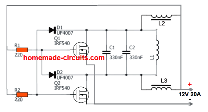
1) Powerful Induction Heater using a Mazzilli Driver Concept
The first design I have explained below is a highly efficient ZVS induction concept based on the popular Mazilli driver theory.
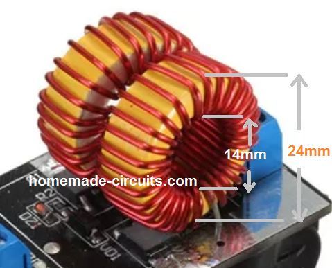
It uses a single work coil and a two current limiter coils. The configuration avoids the need of a center tap from the main work coil thus making the system extremely effective and rapid heating of load with formidable dimensions. The heating coil heats the load through a full bridge push pull action
The module is actually available online and can be easily bought at a very reasonable cost.
The circuit diagram for this design can be seen below:
The original diagram can be witnessed in the following image:
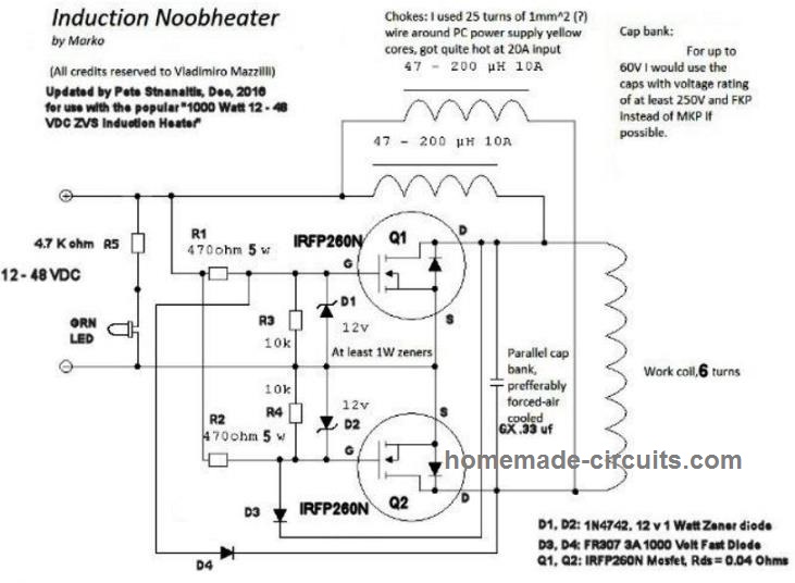
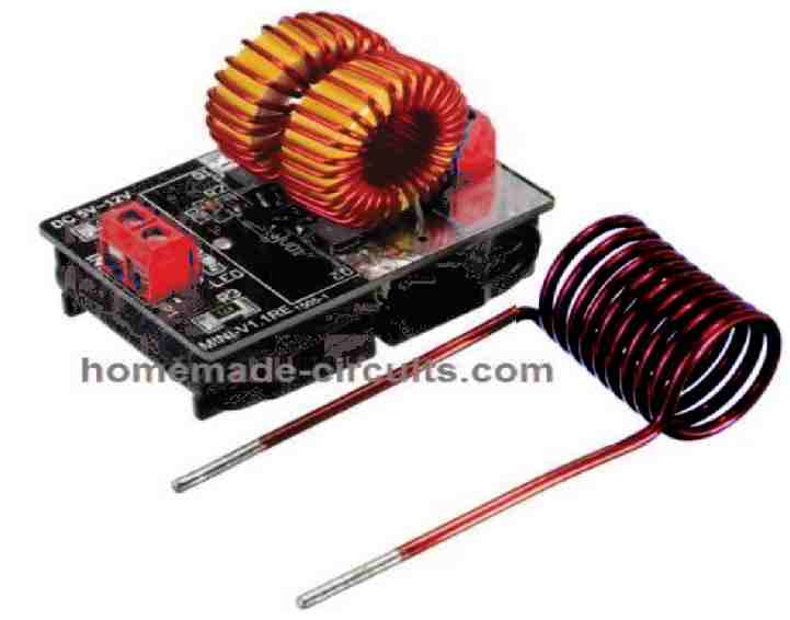
The working principle is the same ZVS technology, using two high power MOSFETs. The supply input can be anything between 5V and 12V, and current from 5 amps to 20 amps depending on the load used.
Power Output
The power output from the above design can be as high as 1200 watts, when the input voltage is raised up to 48V, and current up to 25 amps.
At this level the heat generated from the work coil can be high enough to melt a 1 cm thick bolt within a minute.
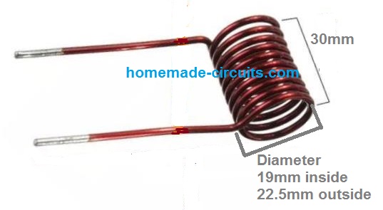
Work Coil Dimensions
Video Demo
2) Induction Heater using a Center Tap Work Coil
This second concept is also a ZVS induction heater, but uses a center bifurcation for the work coil, which may be slightly less efficient compared to the previous design.
The L1, which is the most crucial element of the whole circuit. It must be built using extremely thick copper wires so that it sustains the high temperatures during the induction operations.
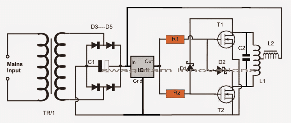
The capacitor as discussed above must be ideally connected as close as possible to the L1 terminals. his is important for sustaining the resonant frequency at the specified 200kHz frequency.
Primary Work Coil Specifications
For the induction heater coil L1, many 1mm copper wire may be wound in parallel or in bifilar manner in order to dissipate current more effectively causing lower heat generation in the coil.
Even after this the coil could be subjected to extreme heats, and could get deformed due to it therefore an alternative method of winding it may be tried.
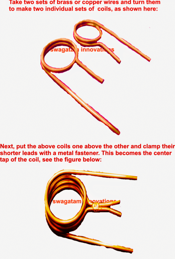
In this method we wind it in the form of two separate coils joined at the center for acquiring the required center tap.
In this method lesser turns may be tried for reducing the impedance of the coil and in turn increase its current handling capability.
The capacitance for this arrangement may be in contrast increased in order to pull down the resonant frequency proportionately.
Tank Capacitors:
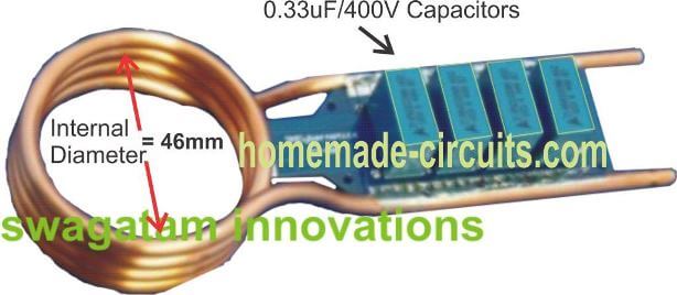
In all 330nF x 6 could be used for acquiring a net 2uF capacitance approximately.
How to Attach Capacitor to the Induction Work Coil
The following image shows the precise method of attaching the capacitors in parallel with the end termianals of the copper coil, preferably through a well dimensioned PCB.
Parts list for the above induction heater circuit or induction hot plate circuit
- R1, R2 = 330 ohms 1/2 watt
- D1, D2 = FR107 or BA159
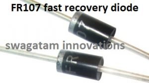
- T1, T2 = IRF540
- C1 = 10,000uF/25V
- C2 = 2uF/400V made by attaching the below shown 6nos 330nF/400V caps in parallel
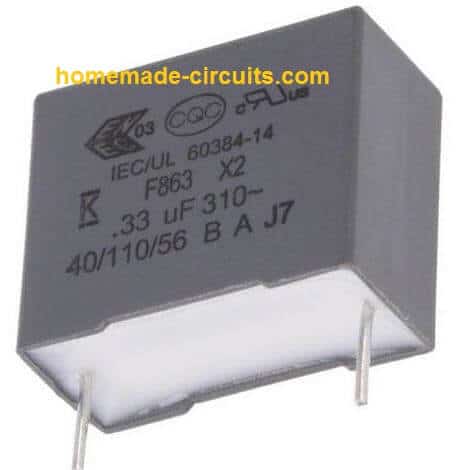
- D3----D6 = 25 amp diodes
- IC1 = 7812
- L1 = 2mm brass pipe wound as shown in the following pics, the diameter can be anywhere near 30mm (internal diameter of the coils)
- L2 = 2mH choke made by winding 2mm magnet wire on any suitable ferrite rod
- TR1 = 0-15V/20amps
- POWER SUPPLY: Use regulated 15V 20 amp DC power supply.
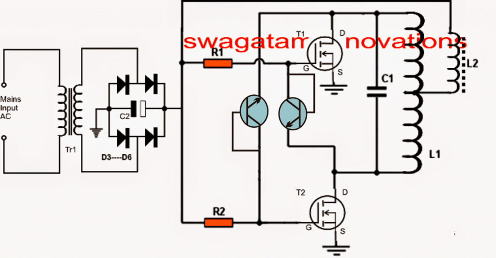
Using BC547 transistors in place of high speed diodes
In the above induction heater circuit diagram we can see the MOSFETs gates consisting of fast recovery diodes, which might be difficult to obtain in some parts of the country.
A simple alternative to this may be in the form of BC547 transistors connected instead of the diodes as shown in the following diagarm.
The transistors would perform the same function as the diodes since the BC547 can operate well around 1Mhz frequencies.
Another Simple DIY Design
The following schematic shows another simple design, similar to the above, which can be constructed quickly at home for implementing a personal induction heating system.
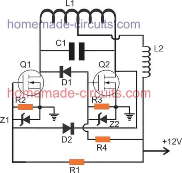
Parts List
- R1, R4 = 1K 1/4 watt MFR 1%
- R2, R3 = 10K 1/4 watt MFR 1%
- D1, D2 = BA159 or FR107
- Z1, Z2 = 12V, 1/2 watt zener diodes
- Q1, Q2 = IRFZ44n mosfet on heatsink
- C1 = 0.33uF/400V or 3 nos 0.1uF/400V in parallel
- L1, L2, as shown in the following images:
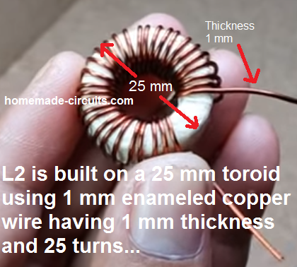
- L2 is salvaged from any old ATX computer power supply.
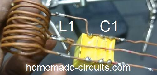
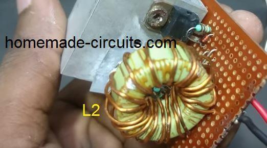
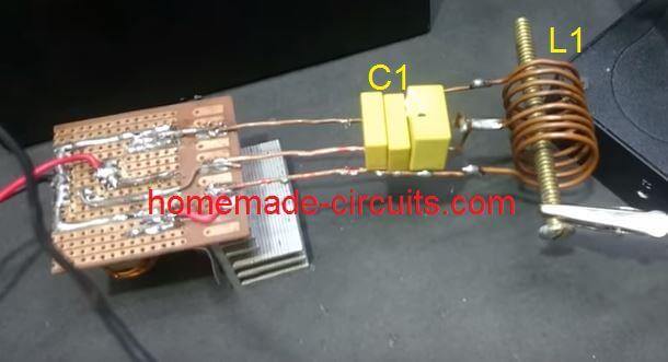
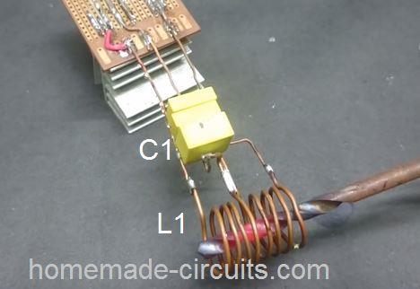
How L2 is Built
Modifying into a Hot Plate Cookware
The above sections helped us to learn a simple induction heater circuit using a spring like coil, however this coil cannot be used for cooking food, and needs some serious modifications.
The following section of the article explains, how the above idea can be modified and used like a simple small induction cookware heater circuit or an induction kadai circuit.
The design is a low tech, low power design, and may not be on par with the conventional units. The circuit was requested by Mr. Dipesh Gupta
Technical Specifications
Sir,
I have read ur article Simple Induction Heater Circuit - Hot Plate Cooker Circuit And was very happy to find that there are people ready to help youngsters like us to do something ....
Sir I am trying to understand the working and trying to develop an induction kadai for myself ... Sir please help me understanding the designing as I m nt so good in electronics
I want to develop an induction to heat up a kadai of dia 20 inch with 10khz frequency at a very low cost !!!
I saw your diagrams and article but was a bit confused about
- 1. Transformer used
- 2. How to make L2
- 3. And any other changes in the circuit for 10 to 20 kHz frequency with 25ams current
Please help me sir as soon as possible ..It will be help full if u could provide with the exact components detail needed .. PlzzAnd lastly u had mentioned to use POWER SUPPLY: Use regulated 15V 20 amp DC power supply. Where is it used ....
Thanks
Dipesh gupta
The Design
The proposed induction kadai circuit design presented here is just for experimental purpose and may not serve like the conventional units. It may be used for making a cup of tea or cooking an omelet quickly and nothing more should be expected.
The referred circuit was originally designed for heating iron rod like objects such as a bolt head. a screwdriver metal etc, however with some modification the same circuit can be applied for heating metal pans or vessels with convex base like a "kadai".
For implementing the above, the original circuit wouldn't need any modification, except the main working coil which will need to be tweaked a bit to form a flat spiral instead of the spring like arrangement.
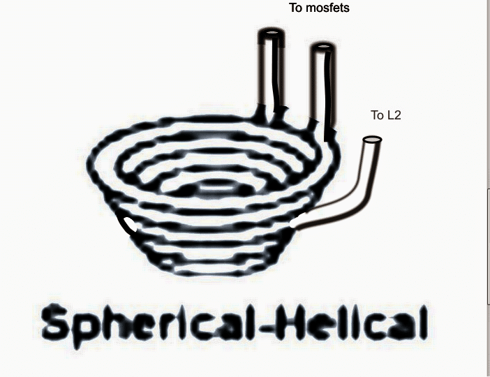
As an example, in order to convert the design into an induction cookware so that it supports vessels having a convex bottom such as a kadai, the coil must be fabricated into a spherical-helical shape as given in the figure below :
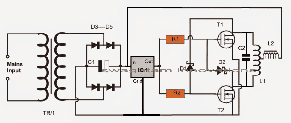
The schematic would be the same as explained in my above sevction, which is basically a Royer based design, as shown here:
Designing the Helical Work Coil
L1 is made by using 5 to 6 turns of 8mm copper tube into a spherical-helical shape as shown above in order to accommodate a small steel bowl in the middle.
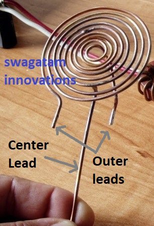
The coil may be also compressed flat into a spiral form if a small steel pan is intended to be used as the cookware as shown below:

Designing the Current Limiter Coil
L2 may be built by winding a 3mm thick super enameled copper wire over a thick ferrite rod, the number of turns must be experimented until a 2mH value is achieved across its terminals.
TR1 could be a 20V 30amp transformer or an SMPS power supply.
The actual induction heater circuit is quite basic with its design and does not need much of an explanation, the few things that needs to be taken care of are as follows:
The resonance capacitor must be relatively closer to the main working coil L1 and should be made by connecting around 10nos of 0.22uF/400V in parallel. The capacitors must be strictly non-polar and metalized polyester type.
Although the design may look quite straightforward, finding the center tap within the spirally wound design could pose some headache because a spiral coil would have an unsymmetrical layout making it difficult to locate the exact center tap for the circuit.
It could be done by some trial and error or by using an LC meter.
A wrongly located center tap could force the circuit to function abnormally or producing unequal heating of the mosfets, or the entire circuit may just fail to oscillate under a worst situation.
Reference: Wikipedia



Questions & Answers
Dear sir which diode can i put in place of FR107
You can use BC547 transistor in place of the diodes. Connect base and collector together with the gate of the mosfet, and emitter to the drain of the other mosfet. Remember this is only a suggestion…
No, only the specified type will work.
Hello sir can I use it for boiling a moving water from pipe.
Helo Salman,
Yes you can do it, but the pipe should be made of iron or steel (magnetic material)
Thank you for the quick response,
So pipe that Water flow inside, is a metal to be heated or as a induction metal(L1)?
The iron water pipe should pass through the center of the coil L1 as shown in the last diagram.
Not worked swgtm. the material not even heat up & both mosfets burnt out. it specified 200kHz frequency. So can i use Astable multivibrator to set frequency 200Khz to drive the coils.
Hi Max,
What did you use for D1/D2 and L2?
FR302 & 40 turns on a ferrite bead as L2
hello swagatam.
Plz suggest a circuit to run cooling fan externally. i bought a amplifier unit the heat sense fan stops automatically after 1 minute. need a solid state cheap circuit to run fan directly from mains. (fan rated 12vdc 0.25amp 2.5w)
Hello Max,
The only solution is to a use a readymade 12V ac/dc smps adapter rated at 500mA or 1amp current, because you won't get below this rating.
Hello Swagatam,
I have built my one successfully with DC power source of 18V connected to L2 while the other side keep 12V to drive MOSFET. I am also connecting ammerter in series to L2 to monitor the current. With some bolts and nuts or steel rod. They can turn red hot without problem. Current goes up from original L1 coil without anything inside to some level according to the object inside the coil. Somehow, I try this with 1/2" diameter steel pipe with 0.5mm thickness. Current goes up and increasing. After a while when pipe is in red hot, current suddenly increase very rapidly and FET burn-out. At this point, everything stop. I have to change FET as it was shorted Drain-Source. I used IRFP250N and diode BYV26E, pretty high rated voltage and current but still failed. Do you have any idea what I did wrong? Is this due to FET or Diode? Thanks.
Helo Sitti,
Try the following circuit, set Rt, Ct for getting 200khz, use L2 in place of "L" and the L1 for RL.
https://www.homemade-circuits.com/2013/09/half-bridge-mosfet-driver-ic-irs21531d.html
This circuit will never allow your mosfets to blow off, according to me.
Is there any alternative power supply? Cause its too expensive to buy a 20 A transformer then make it DC supply. By the way, could I use a power supply with adjuster in order to control the temparature of the induction coil?
sorry there's no direct alternative for high current. You can reduce it proportionately by increasing the voltage, but that would also require modifications in the work coil, the turns will need to be increased while the gauge will need to reduced accordingly.
thanks for the quick reply, I really want to learn more about induction heating. Where I can find a choke coil required L2 because I can't find one of it in some electronics store here in my place, is it okay not to put L2? I want to share my idea to you, I have a circuit design that I found in the internet to control temperature, how can I share it to you?
You won't get the coils readymade, you will have to hand make it as per the details shown in the images and the article info.
You are welcome to share your ideas, please send it to hitman2008@live.in
is it safe that my transformer that is rated 6A only is giving me up to 10A of current. Because i connected it to a bridge rectifier and a 4700uF caps to make a dc power supply, then i successfully make the circuit work but when I measured the current flowing to the transformer using a clamp meter, it gives me up to 10A depending on the metal to be heated. is it still safe for the transformer producing greater current than its rating?
if it's showing more than the specified amps of the transformer means the voltage is being dropped proportionately in the course….so ultimately the total power is never being exceeded.
as far as the above circuit is concerned, the coil would handle current depending upon its thickness, if it's correctly dimensioned it would be safe.
sir supply is 300w or 15v 20a ?
It's 15V/20amp, that's equal to 300 watts
sir, i mean can i use 150v 2amp?
no, it should be @15V, amps is not important can be of any value (not less than 20amps)
Sir, both terminal will be +ve? if yes then; where is -ve terminal? And in MOSFET source will be grounded or -ve?
only the mosfet sources will go to the negative of the supply, no other point of the circuit is connected to the supply negative.
Sir, this kind of power supply(15v, 20a)is not esily available in the market.So, at which minimum voltage and current the circuit will be run?
Vinay, you can use a 12V, 20 amp transformer
Hello Swatam
what changes I should make in the circuit to operate at 220V , two phases, each 110 V and a power of 6kW.
and I'm thinking to cool L1 and L2 with water that circulates inside
this is possible.
Hello Paul,
Sorry, I think that may not be recommended and could require more number of turns for L1/L2…I do not have the data for calculating those.
thank you very much.
the number of turns can prove, but the electronic elements can recommend me what changes should be do.
The configuration will remain as is. The resistors could be increased to 1K 10 watt (wirewound) each, everything will need to be done through trial and error, though.
For the mosfets you can use IRF840, however since mains voltage is involved, the risks of an untoward could be on the cards, I am not recommending use of 220V for this project.
i have built one successfully but my capacitors tanks become very hot….
i am using parallel cap at single point and where the all cap meet(at single point) they get very hot.
should i mount capacitors on pipes at some distance?
yes preferably the caps must be p;aced slightly away from the coil, may be a 6 inches distance will do.
One more thing
At the start current go up very high without anything inside..
you can use a 1000 watt halogen lamp in series with the mains input to the transformer, this will ensure that the initial amp intake does not exceed to dangerous levels.
Thanks Swagatam
I made my induction heater successfully now i want to increase its power..
Can i increase power of this induction heater using more mosfets in parallel?
Please scheme a circuit for parallel combination.
Thanks
Thanks Waqar, to increase power you may try increasing the input current and also the voltage, and upgrade the mosfet with other higher rated ones, parallel combination may not be recommended.
You can select an appropriate mosfet pair from the following article
easydatasheets.blogspot.in/p/mosfets.html
Can i pass the iron or steel tube(from which water which is to be heated) three to four times from the coil L1.
it should be a copper coil, iron will not do.
k.
thanks sir
sir we are making induction heater ckt for academic project purpose so could u tell us about the length and turns of L1,L2
you can find it in this video: https://www.youtube.com/watch?v=pVYMLnXW9uo
can i use a high rated transformer and then minimize the current and voltage by a rheostat.
you may have to do it through a variac, a rheostat will not do.
ty sir.
can i fed the circuit with directly 20 amp or i have to increase it gradually because the insulation of my wire which are use for connection are burning along with mosfet.
what is the reason for the same
increase it gradually, but if the mosfets are also burning it means the circuit is malfunctioning and there could be a fault in the circuit
sir plz help me out.
when i increase the voltage with the variac my bridge rectifier burned out at 7 volt and if i fed the circuit directly my mosfet burned out.
what should i do..
Pratik, it means the circuit is drawing huge currents without load, something is incorrect in your circuit.
try a bridge driver type of circuit instead of the above self resonanat design for reliable results
K..
I'LL CHECK IT OUT