In this article I have explained two simple class-D amplifier projects which can be built at home with extremely high efficiency results. A Class D amplifier is also known as switching amplifier. This technology uses pulse width modulation or PWM for digitally amplifying small analogue music signals into high power, high efficiency audio signals.
Why a Class D Amplifier
The main benefits of this type of amplifier are high efficiency, low cost, with the only drawback being the association of distortion if not cleaned with correctly calculated filters at the output.
Normally all amplifiers are analogue based where the input music or frequency is amplified in accordance with the same pattern that's being fed at the input.
Since a music may largely have exponentially rising and falling contents and also frequencies accompanied with all sorts of amplitudes causes heating up of the devices.
This happens because BJTs and mosfets do not "like" transitional inputs where the signal do not have sudden rise and fall rather gradually transits across the points where the devices are neither fully ON or OFF, this causes a lot of heat generation and power loss
In a class D type of amplifier, the music input is compared with high frequency triangle waves and converted into a PWM "language" at the output. The PWM content stores all the information of the music and translates it back into the connected loudspeaker in an amplified manner.
However since the PWMs will consist of non-exponential pulses where the pulses are in the form rectangular pillars switching ON/OFF suddenly without transitions can result in significant distortions at the output.
In order to smooth out the above issue, a low pass filter is generally incorporated wherein the spikes are smoothed to generate a reasonably good and clear amplified replication.
The proposed design of a class D digital amplifier circuit utilizes the famous 555 IC for the intended comparisons.
Instead of the PWM method here we use an alternative mode called the PPM or pulse position modulation which may be considered as good as a PWM.
Using Pulse Position Modulation
PPM is also known as pulse density modulation due to the specific nature of its functioning.
Here the modulation input is compared with high frequency triangle waves and the output is optimized by varying the position or the density of the generated/compared pulse output.
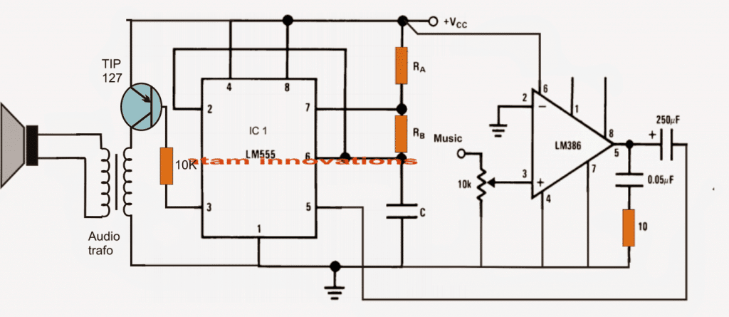
As can be seen in the below class D amplifier circuit design, the IC 555 is configured as a standard astable MV mode, where the resistors Ra, Rb and C determine the frequency of the triangle waves generated at pin6/7 of the IC.
The above high frequency triangle waves are compared with the music input applied at the control input pin5 of the IC.
Here the low voltage music signal is first amplified to some optimal voltage level and then applied at the control input pin#5 of the IC555.
This results in the discussed PPM output at pin#3 of the IC. This is amplified by T1 to a high current output and is fed to a loudspeaker for the required class D type amplification.
The audio trafo does a couple of interesting functions, it amplifies the output for the LS and also to an extent smooths out the harmonics which are normally a part of all class D type amplifier circuits.
A filter capacitor (non-polar) may be tried across the LS for obtaining cleaner sound outputs.
Parts List
- RA, RB, C = To be calculated with some trial and error
- 10 Ohm 1/4 watt resistor = 2nos
- 10K potentiometer = 1no
- IC 555 = 1no
- IC LM386 = 1no
- TIP127 transistor = 1no
- Audio Transformer = 1no
- Speaker 8 ohm 2 watts = 1no
IC 555 Pinout

IC LM386 Pinouts
Switching Class-D Amplifier Circuit
Class-A and Class-B linear amplifiers are commonly employed to amplify audio signals. On the other hand, it might be also feasible to amplify audio signals using a nonlinear amplifier.
This kind of nonlinear amplifiers are generally called "switching" or Class-D amplifiers, since the output transistors found in these devices switch by either completely turning on or completely turning off.
In a switching amplifier, nearly all electrical power is transferred to the load (loudspeaker) during the periods when the amplifier transistors are fully turned on.
The greatest volume of power is dissipated through the transistors while the devices are in the switch-on and switch-off transitions.
The quicker the transition, the lesser the quantity of power given out through the output transistors.
Due to switching amplifiers' layout, the efficiency level of a switching amplifier can go well beyond 90%.
In contrast, Class-A and B amplifiers provide an utmost efficiencies of around 20% and 78.5%, respectively.
An additional advantage of the high efficiency of 'switching amplifiers is that these units have smaller dimensions, lighter in weight, and tend to be much cheaper than Class-A and B counterparts.
Switching Amplifiers makes use of a pulse-width modulator to get the necessary switching procedures.
Audio signals are first transformed into a train of pulses, each of the pulses being directly proportional with the instantaneous audio signal amplitudes in comparison with the fixed-frequency, fixed-amplitude, of the triangular waveform which is used as the reference.
Thus, with reference to the fixed frequency, the signal's amplitude alters the output's PWM (duty cycle).
The compared difference is then amplified and fed to a powerful 8 ohm loudspeaker, which responds by demodulating the PWMs and reproduce an amplified switched audio output.
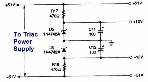
Voltage Splitter Circuit
Power Supply Circuit
The above shown transformerless power supply may be compact but is not isolated from input AC mains, and is therefore extremely dangerous to touch in open and switched ON condition. Extreme caution is advised while building this circuit. If in doubt, it is better to use a transformer based power supply instead.
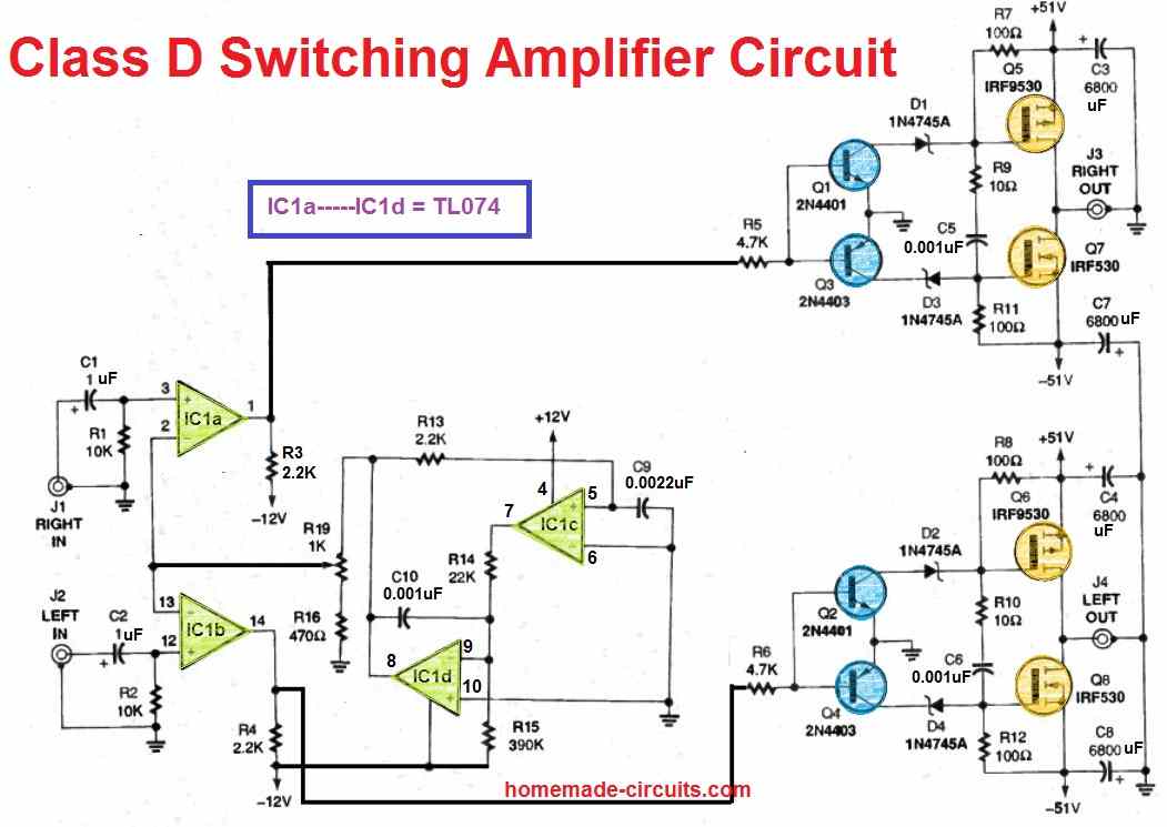
The circuit diagram for the Switching Amplifier can be seen in the above image. An independent 51 V DC supply is necessary to energize the Amplifier circuit.
The 51 V supply source is applied to a set of Zener diodes, D5 and D6, and it is smoothed through capacitors C11 and C12 in order to get a 12 V DC source for the amplifier circuit.
Additionally, portion of the 51 V DC source overrides the Zeners to supply the stages of the circuit which are supposed to work with 51 V DC directly.
How the Circuit Works
The right and left audio frequencies are applied to the switching Amplifier circuit via connectors J1 and J2, respectively.
A couple of stages of a TL074 op amp, IC1c and IC1d, produce a 4 V peak-to-peak, 50 kHz triangular reference waveform.
The produced waveform is subsequently applied to the potentiometer R19, that supplies a variable reference point to the voltage comparators.
This makes it possible for the amplifier to utilize the input signals with amplitudes which range from 1 volt peak-to-peak to 4 volts peak-to-peak.
The additional a pair of op amp sections, IC1a and IC1b, work as comparators to generate the pulse-width-modulating output for the left and right channels of the Amplifier.
In the amplifier right channel, the voltage comparator output is connected to the bipolar conversion circuit via a current limiting resistor, R5.
The converting circuit features a positive and negative "terminal"; Q1, D1, and R1 which act like the positive terminal, and Q3, D3, and R11 which form the negative terminal.
Both terminals are linked with ground by means of the emitters of transistors Q1 and Q3, delivering a reference level for the converter.
The converter set up leads to 17 volts appearing across Q1, Q3, and Zener-diodes D1 and D3.
Adequate amount of current is therefore available to defeat the power MOSFET gate capacitance; which switches on and off the power MOSFET complementary push-pull output stage Q5 and Q7, at a very fast rate.
The amplifier's right and left outputs are obtained from the jacks J3 and J4, respectively. The output is able to deliver a total power of 60 watt RMS to the connected 8 ohm speakers.
The speakers enable the demodulation of the signal and generate an amplified audio output. With output power at the peak, the current consumption from an 8 ohm dynamic speakers will be roughly 1.2 amperes at 51 V DC.
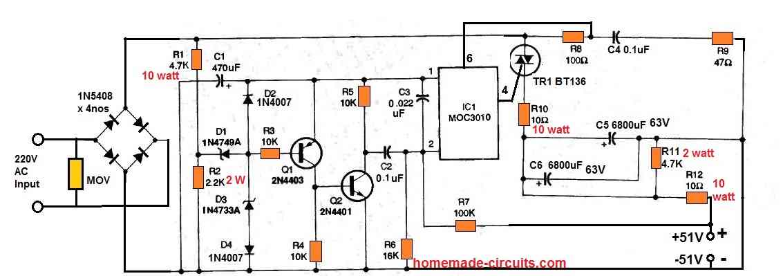
Power Supply
Next, I will talk about the power supply. The second figure shows the circuit diagram of the power supply circuit.
The AC voltage obtained from PL1 supplies to the bridge rectifier BR1, that delivers a fullwave output of roughly 165 V DC.
The configuration built around the parts R1, R2, D1, D3, and D4 produces a train of of 5 V pulses which supply a couple of essential characteristics:
First the pulses are utilized as a 5 V supply source intended for tailoring the pulse shape and monostable circuit by means of D2 and C1.
2nd, the pulses activate opto-coupler IC1 and triac TR1 through the pulse shaping configuration created using Q1, Q2, and R3 R5, and the monostable circuit structured around C2 and R6.
Resistor R2 fixes the highest PWM and consequently the highest level of output voltage. If no feedback is used, the unfiltered peak voltage can be approximately 90 volts.
To get the required 51 V output for the switching amplifier circuit, the feedback configuration built using R6, R7, and C3 reverse biases the opto-coupler anytime the output voltage becomes greater than 51 volts.
This subsequently pushes TR1 to switch off as the unfiltered voltage runs towards zero volts. The RC feedback circuitry therefore adjusts the output voltage by making an effort to alter the IC1's conducting status.

Questions & Answers
Hi Dave,
I have a problem,
I need to know how to couple the output of this vintage radio to a class d amp. I want to replace the power output transistor with the class d amp. The input impedance of the class d amp is 10k ohms. I beleive its best to use a coupling capacitor and a signal attenuator instead of using direct couplimg. So if you use a coupling capacitor how would you calculate the value and add a signal attenuator.
Thanks in advance,
Jeff Miller
Hey Jeff,
Yes, using an AC coupling capacitor is the correct and safest approach, especially if the original transistor stage has a DC bias that you do not want to feed into the Class-D amplifier.
Since your amplifier has a 10k input impedance, you can calculate the coupling capacitor using the high-pass filter formula:
C = 1 / (2 * π * R * f)
where:
R = 10kΩ (amplifier input impedance)
f = lowest audio frequency you want to pass.
For example:
20 Hz -> C ≈ 0.8 µF (use a standard 1 µF film or non-polar capacitor)
50 Hz -> C ≈ 0.33 µF
100 Hz -> C ≈ 0.15 µF
A 1 µF film capacitor is generally an excellent choice because it passes the full audio range with negligible bass attenuation.
If the radio’s output level is too high for the Class-D amplifier, you can add a simple resistive attenuator after the coupling capacitor. For example:
10k series resistor
10k resistor from the amplifier input to ground
This reduces the signal by approximately 50% while maintaining a reasonably high input impedance. If more attenuation is needed, you can increase the series resistor to 22k or 47k while keeping the lower resistor at 10k.
Hi Swagatam,
Thanks so much for your help I really appreciate it. So is the best to couple the signal
from reference point 51? I think its a better choice then 52 do you agree?
Thanks again,
Jeff.
No problem Jeff, I am happy to help you, however I have no idea what the number 51 and 52 means, could you please elaborate or maybe explain your circuit diagram to me…
Hello please I have an lm358 and I first want to amplify the alternating voltage in order to maintain 1V at the output. Then I would like to center my signal at 2.5V
Hi, currently I am not able to figure out the circuit diagram for this request…
Thank you boss, Real hobbyist,
you are inspiring the coming generation.
You are most welcome AK, I appreciate your kind words…
Hi Mr Swagatam I’ve been following your blog for many years and it’s so inspiring and the most fascinating now is class d power amp. I am a musician and I would like to have 2000w class d power amp schematics. please can you help me with it? Thanks.
Thank you Chris, I truly appreciate your kind words!
I think you can try modifying one of the circuits explained in the following article, so that it can deliver a 2000 watt power output:
https://www.homemade-circuits.com/4-efficient-pwm-amplifier-circuits-explained/
Initially try with the original setup, if you succeed then try modifying the MOSFETs for generating the specified amount of power…
hi sir pls is there a way to use two irf530 on the second circuit?if it’s possible pls explain to me how. thank you sir.
Hi Abubakar, sorry, no, that may not be possible. You will have to do exactly as shown in the diagram.
The power-supply is very dangerous!!
The amp is nice 🙂
The power supply is unseparated and an absurdly life-threatening design.
It is not separated from the mains. If you touch the amp it will kill you 🙁
Once again… the amp is a very nice design 🙂
Thanks for yourfeedback….You are right, in that case you can go with a transformer based power supply, it will be much safer and is recommended.
im very interest about this two class d circuits.how second circuit of amplifier working clearly without filter coil and capacitor? please reply me.and how i need for audio transformer for first circuit? can you give me winding details
An audio output transformer can be purchased from any online store or from an electronic spare part retailer.
if is possibel having amplifier hi potentiel class D with 555?
Do you mean high voltage class D amplifier using 555 IC??
What type of audio trafo can I use in the 555 circuit
Hi Mr Swagatam; Ref. Above Class D amplifier. although no microfon connection it sounds like a musical organ. So I aim to remove darlington pair and audio trafo and replace any transistor and additional capacitor since I need no louder output at home. Please send your opinion.-Thanks
Hi Suat, did you try the circuit with an audio music input? Please try it and let me know the results…..
yes if low audio is acceptable then you can connect a small 16 or 32 ohm loudspeaker directly with the pin3 of IC 555, however a series 100uF capacitor will provide added safety to the speaker, so you can try that also….
Hi Mr. Swagatam; The result is; 1- Speaker sounds like an organ If there is no audio input. (input voltage about 7 volts) 2- If audio input is on then possible to hear some small reaction on the speaker as / like interference. However I should say that after your warning I changed the previous core and used a screwdriver (dia. 6 mm since impossible to find ferrite type here in my location) As a result please advise which one is reasonable to use this class D or a circuit with only LM386 (without 555) since we are going to remove the audio transformer. I also have a simple circuit consisting of the only LM386 and some capacitors and resistors (no 555). The only problem is there is little interference if I touch the volume resistor.-Thank you so much.
Hi Suat, a class D amp is normally used for getting extreme efficiency with higher loads, in your case the class D is not required. You can directly use the LM386 IC for the amplifications
Hi Mr. Swagatam;
I have tried the above class D with the parts in my hand. I used perno / pin (dia. 18mm) as coil / core with turns 25 (to Tr127-collector) and turns 100 (to speaker – and +). However I also used and tried tip32 and bd136 as “darlington pair” instead of tip127. The result seems positive since the it is possible to hear wireless sound like a musical organ notes but the problem is tip32 and bd136 are exposed to overheating after voltage about 10 volt even one in the pair is gone pop. I hope I will hear some critics from you(P.S: I used 100 and 15K resistors in the darlington pair)- Thanks
Hi Suat, if the output inductor does not match with the carrier frequency then it may cause heating up of the transistor. You can try with an iron core transformer low voltage side winding as the inductor, and check the response.
Hi Mr Swagatam;
My PC audio output is out of order I have been using simple usb auido device and I have aimed to to use the above class d amplifier circuit with the 555 and lm386 parts. Please advise more about audio trafo which I can make at home and also whether I can use tip32 instead of tip127-Regards
Hi Suat, you can try a small ferrite transformer. 25 turns at the transistor side, and 100 turns on the speaker side, however this ratio may need to be experimented a little for improving the results
Thanks Swagatam, but sorry what about the wire diameter of both turns? Thanks again
Wire thickness is not critical since the power output is nominal, you can use 0.3mm wire
Please Sir, I could not get the 250uf /50v Electrolytic Capacitor,any replacement?
Lawal, which circuit are you referring to? Please post the comment under the same article…
Please Sir is t13 the audio transformer,is it double layer winding using the required wiregauge given?
Please Sir, I was referring to the Class D amplifier, the 250 uf capacitor placed at pin5 of the 555 timer and LM386 respectfully. Please Sir, can I use NE555 timer in place of LM555timer
Sorry, I did not notice it, yes any nearby value will work…and any and all IC 555 will work.
Lawal, it’s an audio output transformer. You can build it at home also by winding primary turns having approximately 200 ohms value, and secondary turns upto 1 k ohms on any ferrite core. Use any super enameled copper wire, as thin as you can manage.
you can try this circuit:
https://www.homemade-circuits.com/2012/10/1-watt-led-driver-using-joule-thief.html
i can change TIP127 for TIP142 ?
sorry…it's TIP147
you can change it with TI147…
Hi swagatam,can i use transtorized power amp(5w8ohm) in place of LM386,if so should i change output transistor across audio transformer.And also what is power output of this circuit.
Hi Charan, yes any amplifier which can work with the same voltage as the 555 will do.
the power output will depend on capacity of the output transformer wattage and the TIP127 capacity, these two could be upgraded for higher power outputs
Ok thanks so just the way the circuit is now would 50v be too high to test it at I was looking at the A1266 in the circuit seeing that collector emitter voltage is 50v I was thinking it should be a bit lower.
the MJE are rated to handle much higher than 50V so it would be OK to use 50V for these, not sure about the power transistors…you can probably think about using some other variant such as 2N3055 etc or TIP35/36 which are rated to handle 100V
So If i was to add (4) 2sc2922 and (4) 2sa1216 I could replace MJE340/350 with tip TIP122 and TIP127. what about the MJE340 at the input, would I need to replace that one?
Also what would the supply voltage be maximum, would it be about 50v +/-
TIP122/127 are Darlington devices not sure how they would respond here? you can try nevertheless.
50V would be a good value to start with.
could ouu check this amplifier
circuitswiring.com/circuit-diagrams/22/High-Power-amplifier-450-Watt-with-2-set-sanken.jpg
Question do you think I could add atleast 2 more pairs of output transistors to this circuit only adding and extra 10ohm and 0.1ohm to base and emmiter to get more power?
Would anything need to be changed or added?
Swagatam,
is the 450 watt amp by Ainsworth working well now? He asked you to check the circuit, is it ok? If it is can you please share with me the power supply secondary winding center tap voltage.thanks.
each transistor would require a massive 1amp for saturating…so for 4 transistors it would be 4amps….I don't think the MJE340/350 would be capable for delivering this much current…so make sure these are upgraded with more powerful devices along with their bases resistances which will need to be reduced….only then it would be possible
Thanx. How? Do u publish any article for above written requirement? Or sugest a ckt.
I have one article explaining LM386 IC, you can find it here:
https://www.homemade-circuits.com/2012/08/ic-lm-386-datasheet-explained-in-simple.html