The IC 555 is a popular timer IC which we can use for making different types of inverter circuits. With a few extra components we can make the IC 555 generate switching pulses, and then we can use these pulses for converting battery DC into AC power.
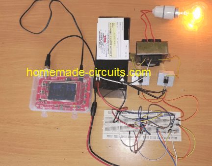
In this article we will look at 5 different inverter designs using the IC 555. These include simple square wave inverters, full bridge inverters, SPWM sine wave inverters and one design with automatic battery protection.
Each design works in a different way and has its own good points and limitations. So you can select the design according to your requirement and then visit the respective detailed article to understand the complete circuit diagram, component values and working principle.
Important: These circuits can generate dangerous high voltage AC. Some designs also use high voltage DC internally. So let us be careful and never touch the circuit while it is powered. We must also check the circuit properly before building it, since not every circuit has been practically tested.
1. Basic IC 555 Inverter Circuit
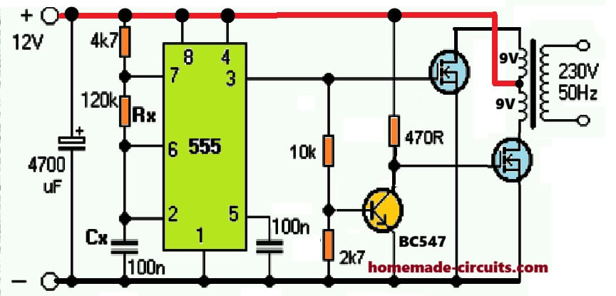
This is one of the simplest types of inverter circuits using an IC 555 timer. Here we configure the IC as an astable oscillator so that it can generate low frequency switching pulses.
We can use these pulses to operate a power transistor or MOSFET stage connected to a suitable transformer. The transformer then converts the battery voltage into a higher AC voltage.
This type of transistor inverter can be quite simple to build, so you can use it for understanding the basic working principle of an inverter.
The output is generally a square wave, but it is not the same as the pure sine wave that we get from a normal household AC supply.
We must select the oscillator frequency, transistor ratings, transformer rating and battery capacity correctly, so that the circuit can work properly.
Read the complete circuit here: [BASIC IC 555 INVERTER ARTICLE URL]
2. IC 555 Full Bridge Inverter Circuit
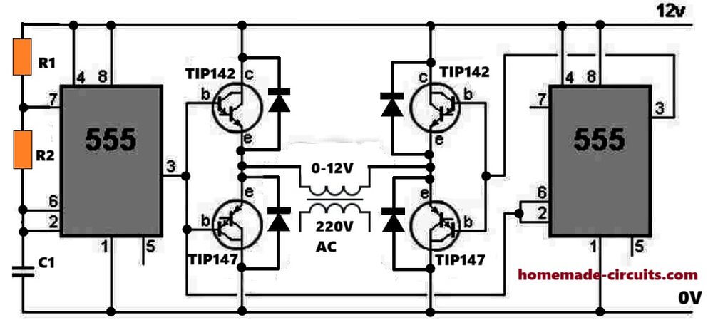
A full bridge inverter uses four switching devices arranged in an H-bridge configuration. Here the switching devices work in pairs so that they can reverse the polarity applied to the load or transformer.
We can use the IC 555 as an oscillator for generating the required low frequency switching signal. But we also need additional circuitry to produce the correct switching sequence and prevent the two devices in the same bridge leg from conducting at the same time.
A full bridge arrangement can make better use of a suitable DC supply and transformer, but the actual performance depends on the circuit design and the switching devices we use.
The original circuit shown in this design uses an unusual supply arrangement, so we must check it carefully before construction. We should not assume that it is a tested 200 watt inverter.
Read the complete circuit here: [IC 555 FULL BRIDGE INVERTER ARTICLE URL]
3. IC 555 Modified Square Wave Inverter Circuit
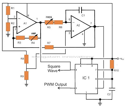
A basic IC 555 inverter produces square wave AC. But if we want to get a waveform closer to a sine wave, then we can use a pulse width modulation technique.
In this design an operational amplifier circuit generates the reference waveforms required for producing SPWM pulses. The IC 555 is then used to generate pulses whose widths change according to the modulation signal.
These pulses control the power switching stage and transformer. With a properly designed output stage and suitable filtering, we can get an AC waveform that is closer to a sine wave.
The quality of the output depends on the PWM generation method, switching stage, transformer, output filter and load.
This circuit is more complicated than the basic square wave inverter, so we must check the oscillator frequency and switching arrangement carefully before building it.
Read the complete circuit here: [IC 555 Modified Squarewave INVERTER ARTICLE URL]
4. IC 555 Sine Wave Inverter Using SPWM
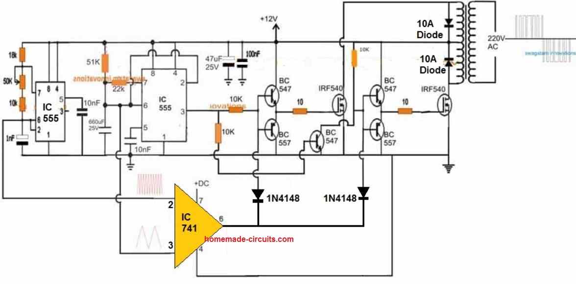
This is an easy way of making an SPWM inverter using the IC 555 together with an operational amplifier such as the IC 741.
In this design a high frequency triangular waveform is compared with a lower frequency reference waveform to produce pulses with changing widths. These SPWM pulses are then used to control the inverter power stage.
The IC 555 oscillator provides the timing signal, while the additional circuit generates the modulation required for shaping the output waveform.
The good thing about this method is that we can build the timing and modulation sections using commonly available components.
But we must make sure that the switching frequency, output frequency and gate or base drive signals remain properly synchronized. A suitable output filter may also be required, depending on the design.
Read the complete circuit here: [IC 555 SPWM INVERTER ARTICLE URL]
5. IC 555 Transformerless Inverter Circuit
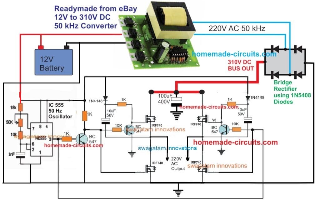
This design uses an IC 555 oscillator to control a full bridge made from four N-channel MOSFETs.
Unlike a normal low voltage transformer inverter, this arrangement uses a DC-to-DC converter module to get a high voltage DC supply. The MOSFET bridge then switches this DC supply to produce an AC output.
So in this design the high voltage conversion takes place electronically instead of using a conventional low frequency transformer.
This arrangement can reduce the size of the magnetic components, but it also needs some extra care during design. The DC-to-DC converter, MOSFET bridge, gate drivers and protection circuits must all be suitable for the operating voltage and load.
Safety warning: The high voltage DC bus can be lethal even when the input comes from a low voltage battery. So we should not treat this as a beginner circuit.
Read the complete circuit here: [TRANSFORMERLESS IC 555 INVERTER ARTICLE URL]
Which IC 555 Inverter Circuit Should You Choose?
The best design depends on what you want to build.
A basic square wave inverter is the simplest starting point, so you can use it to understand how an inverter works. A full bridge design may be suitable when its switching and driver stages are designed properly. An SPWM inverter needs some extra circuitry, but it can produce a waveform closer to a sine wave.
A transformerless inverter is more complicated since it uses a high voltage DC bus. A design with Arduino battery monitoring adds control and protection functions, but it also needs suitable programming and testing.
Before selecting a circuit, let us check the required output voltage, output frequency, continuous power rating, battery voltage, transformer rating and expected load.
We should not select an inverter only by looking at the power rating mentioned in the circuit description. The actual output power depends on the complete design and the ratings of the components we use.
Final Words
The IC 555 is a useful timer IC which we can use for making many types of inverter circuits. By changing the oscillator, modulation circuit and power stage, we can build different inverter designs for different purposes.
The 5 designs explained above gives us a starting point for understanding these possibilities. You can visit the individual circuit articles to see the detailed schematics and explanations before selecting a design for construction.


Questions & Answers
Please sir what is the Watt of this inverter ?
Will depend on the trafo wattage and the battery AH capacity.
Please can u help me and tell me how may i know the transformer WATT because i have UPS transformer but i don't know it WATT?
apply mains AC across its mains side and then using an AC ammeter measure the current directly across the other side wire ends…then multiply the reading with the voltage specification of those wires
hi swagatam for the first diagram what is the rating of the transformer
Hi Davis, it can be as per your own desired specification….
i am greatfull so much and i am very appritiate for your site
pls sir, can you help me with the diagram of IC 4047 and fets 1kw diagram since thats the only ic i can get around. Thanks
Eric, you can try the following design
https://www.homemade-circuits.com/2014/11/48-v-inverter-circuit.html
you can replace the BJTs with FETs, and use 100 ohm resistor with their gates
sir what are the appliances does the circuit above will power ?
It will power most of the equipment which use internal SMPS
sir can the circuit above power a fan without a noise???
you can connect a capacitor with the fan to reduce noise
I av 12v 0 12v to 230v AC, will it work on the cirvuit above? sir
yes ti will work
sir can i connect the above circuit with 6-0-6 ? and how the watt be ?
it can be used if the battery is also 6V
I am using a simple transformer. When I press ctrl+E, but tell me that how can i calculate these values like primary inductance, secondary inductance etc. Can you suggest me some calculator for this purpose?. My requirements are below: primary voltage: 220V, 50Hz secondary voltage: 12V, 1A
I have already discussed how to design an inverter transformer in this website, you can refer to that article. you can find it through the search box above or by Google search..
Is the citcuit square wave or sine wave? If square wave where to attach chopper to it and make it modified sine wave? Thanks
it's square wave, add chopper to the bases of the NPN/PNP
sir what is dis chopper all about. is it a circuit. if yes can u upload it, let me take a look at it. thanks
you can learn the details here
https://www.homemade-circuits.com/2013/04/how-to-modify-square-wave-inverter-into.html
Domnule Swagatam Majumdar,va rog sa-mi spuneti daca acest invertor poate fi folosit la o pompa electronica pentru centrala termica,atunci cand reteaua de curent a cazut.pompa consuma 40w.daca nu ce modificari trebuie aduse.Scuze ca nu vorbesc engleza.pls raspundeti.tank you
da, acesta poate fi folosit pentru orice aplicație preferată ca pe alegerea ta
hello sir swagattam, I designed an inverter, it is working perfectly. but my problem is '' the heatsink ther was not fan connected to it and it is hot so much. I need an automatic fan circuit for cooling of the heatsink whenever it start heating the fan will automatically blowing, and whenever it stop heating the fan will automatically stop…. thanks
hello chucks, you can try the following concept
https://www.homemade-circuits.com/2015/03/fan-speed-controller-for-heatsink.html
Please Sir help me as you are doing to us. please guide me how i am going to calculate battery mAH . Assume that the battery is 12v 100mAH and connected with 500watt inverter if i connect 7 phone chager each is 6 watt and 9 watt CFL how many are hours may the battery's charging take before the it finish
I guess you meant to say 100AH battery??
you simply have to divide the battery AH with the load current, and multiply the result with 0.6, that will give you the approx battery back up time.
If i get u for example if my current is 9 watt and my battery is 100AH THE ANSWER IS 100/9=11.1*0.6=6.6 hours ??
It should be load current, not load wattage….your procedure was correct but in place of 9 watt you must apply current.
current can be found by dividing 9 watt with load voltage.
thank sir may GOD expand ur idea more again
is current the same with amp?
amps = 1W / 230V
= 0.004348A ??
yes that's correct. current is measured in amps.
thank u sir
My another Qestion Sir, for instant if i want to modify an low watt inverter less said 50watt please what and what do i going to change or to add. may i going to change height voltage transformer or i am going to add more transistor in pararal please which one should i going to do??
what modifications do you want to make??
hello sir,
I'm very grateful you have deigned to answer my questions by posting an inverter circuit NE555 ic that works on ferrite transformer, I really hope you do not get bored if I will be asking a lot more about this circuit.
I pray that God bless your family
You are welcome Ningrat!!you can feel free to post new comments
Thank you sir,
I am having trouble finding diodes past 10 amperes, .. is there a best solution for it
you can try 6A4 diodes, see if they work alright?
sir, this circuit produces high frequency ac voltage 50kHz whether it can converted into low frequency ac voltage between 50Hz – 60Hz
Ningrat, the Rt, Ct values in the second circuit determines the 50Hz frequency for the load.
you can get the formula in the datasheet of the IC
if we change the value of Rt and Ct to get 50Hz whether it could be applied in the ferrite transformer?
I mean a string of additional output transformer that will turn into a 50Hz 50kHz frequency
ferrite transformer is supposed to be connected with the first diagram which has 50 Khz frequency, the lower circuit needs to be set at 50 Hz….
the load or appliance can be directly connected the lower circuit mosfet.
the 50 khz from the top circuit is fed to the second circuit through the bridge rectifier
if the output of the circuit is converted into a dc voltage using a diode bridge and then a dc voltage is converted back into an ac voltage what it could be?
series such as what can turn into a dc voltage low frequency ac voltage in this issue?
ferrite core can be operated only with high frequency, that's why initially high frequency is used for stepping up the battery voltage to 220V and then it is converted back to low frequency for our home appliances.
Sir,
series such as what is used for converting high frequency to low frequency
the four mosfets are toggled at the low frequency 50 Hz for executing the 50 Hz AC on the load