One big issue that most GTI manufacturers struggle to implement effectively is, what is commonly known as "islanding", the following discussion throws light on this important factor and tries to find a solution. The issue was pointed out and clarified by Mr. Dennis, I have explained more.
What's GTI Islanding
G'day,
With any luck at all you are Swagatam Majumdar.
I was intrigued with your Monday, August 19, 2013 Homemade 100VA to 1000VA Grid-tie Inverter Circuit, with the 555 & 4017 but have one question that you may be able to help me with:
I understand that the circuit will not start without existing grid voltage, but what causes it to shut down with a grid blackout? Is it just that the "load" of an unpowered grid is such that the inverter cannot feed it, so its output is effectively "shorted" by the grid removing the 12V supply?
If so, it appears to be a bit of bad luck for the electricity authority if your line is being worked on and is open (i.e. no street load)! There also appears to be no current limit control of the FETS.
Can you please clarify the operation of this part of the circuit?
Thanks,
Dennis Gibson
Canberra
Analyzing the Circuit Issue
Thanks Dennis,
With no grid power, the circuit would become completely inactive because there would be no voltage to operate the ICs and the mosfets.
I did not quite understand the following statements:
.....an unpowered grid is such that the inverter cannot feed it, so its output is
effectively "shorted" by the grid removing the 12V supply?
If so, it appears to be a bit of bad luck for the electricity authority if
your line
is being worked on and is open (i.e. no street load)! There also appears to
be no current limit control of the FETS.
Yes. there's no current control feature in the design, but can be added easily, not a difficult thing to do.
Best Regards.
Feedback
G’day Swagatam,
Thanks for your response. OK I understand that without grid mains being present, the circuit can’t start up, but if the system is running into the grid, it can effectively power itself from its own output.
As I see it, the only thing that will stop it if the grid goes into blackout is the “load” on the grid. So if the grid fails in such a way that there is no “load” seen by the GTI, (such as an open circuit feed in) then once started it will happily continue supplying what it thinks is the grid (now unloaded) and its own sync power supply from itself.
This creates the problem that the electricity authority engineers called “islanding”, where the output of one GTI is powered from the output of another GTI on the same circuit. This can happen if a grid feed is broken, AND there is no other significant electrical load on the isolated grid section (or island).
This can create serious problems and electrocution risk for grid workers, but I do not know how to detect the difference between mains voltage from the grid, and GTI voltage to an “isolated” grid.
I just wondered if your schematic design somehow achieves this. It can be tested quite easily by running the GTI into a “grid” with no load, then switching off the “grid” circuit, removing the mains excitation, but leaving the sync power transformer connected to the main output transformer secondary. I suspect (surprised if it didn’t) that it will self commutate and keep generating!
Fixing the Islanding Issue
Thanks Dennis,
Now I got it, and I think I completely forgot to address this issue in the article.
I have an idea though, the basic waveform design of the grid output and my circuit are different with their pattern.
The sample frequency applied at pin5 of the first IC 555 receives about 100 Hz when its from the grid mains.
Now if grid happens to fail, the circuit voltage which is a PWM will loop up and get applied at pin5 of the IC, since it would be a PWM would have a much higher frequency than the grid counterpart.
We can include a frequency to voltage converter stage which would monitor and detect the above change in frequency and convert it into an appropriate signal that could be further used to cut off the entire circuit into a stand still or this signal could be used break some kind of initial latch positioned for holding the circuit into a functioning mode while the grid was present.
A suitable frequency to voltage converter can be studied here and used for the proposed application.
https://www.homemade-circuits.com/2013/12/vehicle-speed-limit-alarm-circuit.html
Problem Solved
G’day Swagatam,
Yeah, OK. From what I have seen, commercial units use a PPL “flywheel” oscillator phase locked to the mains in. If the mains fails, then as you suggest the now self excited loop will not be exactly the same so the PLL phase comparator error signal will change rapidly, attempt to re-lock, and this can be sensed, and trigger a shutdown.
Either way, it does add more complexity to the circuit, which then leads to a micro to help make the decisions. I did like your two chip example schematic though!
Cheers & thanks for the discussion.
DG
Canberra.
G'day Dennis, Very nicely explained, thanks for sharing it I really appreciate it.
Cheers:)


Questions & Answers
Hello Sir,
I wish to have a System with Multiple AC Source (Solar, Wind, DG) with Output 220V and Say Different Power Ratings i.e. 500W, 700W … I would like to Combine all the Powers to Sum up and channel to Load according to the Demanded Power by Load. These Sources are External and Can not be Controlled.
For this i was Planning to First Convert AC to DC individually for all Sources and then to combine all DC’s and then again to invert the Final Sum up DC using a Inverter. in Such a manner that Inverter Power output is Sum of All Powers Provided by Different Sources.
Can you Suggest an Appropriate Circuit which could help me in Getting out of this Issue.
Thanks
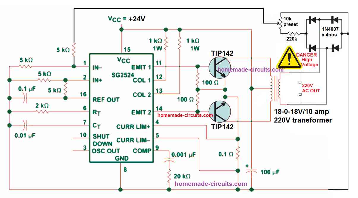
Hello Arpit, yes that’s possible, you can try the following simple full bridge module for converting the high voltage DC back to 220 V AC
Thanks for you both.
Can you please put a brief note about (sync-grid-PPL……)
Thank you intlegent people
Thanks Sasa, possibly I'll try to include it soon.