The simple gate open and close controller circuit is designed to operate the gate through a couple of push buttons manually, it can be also modified for implementing the activation through a remote control.
How it Works
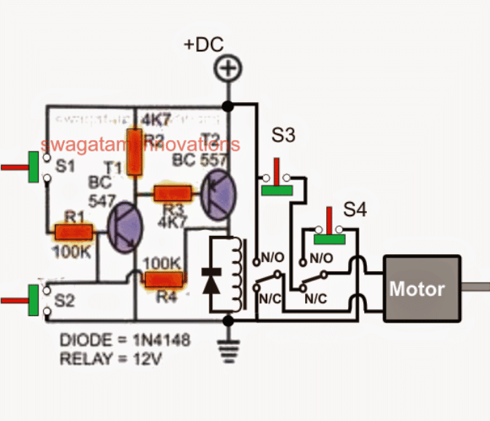
Referring to the shown, simple gate open, close controller circuit below, we can witness a rather straightforward configuration, essentially comprising of a transistor latch stage, a DPDT relay stage and a few push to ON/OFF switches.
The push switches S3/S4 play an important role in the circuit and ensure that the motor never gets overloaded when it reaches its end limits.
The images of the switches which are ideally suited to this application is shown just below the circuit diagram. These are quite popular and can be easily procured from any relevant electronic retailer.
Circuit Diagram
Parts List
- Resistors are all 1/4 watt 5%
- R1, R4 = 100k
- R2, R3 = 4.7k or 10k both
- Relay diode = 1N4007
- T1 = Transistor BC547
- T2 = Transistor BC557
- Relay = 12V DPDT
- S1, S2 = Push button switches
- S3, S4 = push to OFF as shown below
Set Reset Push Switches
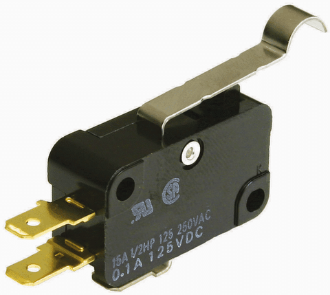
The above Switch is to be used for S3, S4
Transistor T1, T2 along with the associated parts form a reliable latch circuit, S1 and S2 are ordinary push-to-ON switches, where S1 is rigged as the "set" button, and S2 as the reset button, which work for opening and closing the connected respectively.
S3 and S4 are fixed across the end travel points of the gate mechanism, such that the gate pushes these OFF each time it reaches the end destinations, and releases while it moves away from the destination or while the gate is in the course of its travel.
Assuming the gate to be in the closed position initially, we can expect the following scenario:
Operational Steps
S3 in depressed position by the gate and therefore in the cut-off mode.
S4 in released position and therefore contacts closed and switched ON.
The latch circuit switched OFF, and so is the DPDT relay.
The DPDT relay contacts are at the N/C points.
With the above situation, pressing S1 initiates the following course of actions:
T1 and T2 instantly latches, actuating the DPDT relay in the N/O positions.
The motor now begins running through the supply via the S4 and the DPDT relay N/O contact supply in the set direction, enabling the gate to operate with an opening action. This also releases S3 in the process.
As soon as the gate reaches the end limit or the end destination, and opening up fully, it presses S4 cutting off the supply to the motor. The gate now halts and comes to a stand still.
How Motor Rotation is Flipped
This position can be maintained infinitely, until S2 is pressed, which breaks the T1/T2 latch, and deactivates the DPDT relay forcing its contacts to move across the N/C points.
This immediately flips the motor polarity causing the motor to rotate in the opposite direction and enables the gate to reverse back to its closing position. While in this mode the motor gets its power from S3, but only until it reaches its earlier destination, ie. in the closed position, when it presses S3, cutting off power to the motor and yet again disabling the motor.
The gate maintains this position until S1 is pressed yet again for initiating the opening action of the gate...thus the open/close operation of the gate is simply implemented by actuating S1 and S2 switches manually.
In order to execute a remote controlled open, close action of the gate, S1 and S2 could be replaced with momentary relay contacts, and the relays operated through the receiver unit of the remote control.
Any standard 400 MHz RF, 2-relay type remote control modules could be used for the stated remote open, close control of the gate.


Questions & Answers
hello Freddie, I have one related design posted in this blog, you can check it out here:
https://www.homemade-circuits.com/2015/07/automatic-sliding-gate-controller.html
Good day sir! Sir my problem for the automatic-sliding-gate-controller is automatically close, i need manual closing sir. And also the 10-15 min. delay off sir! willing to wait sir! Very glad that you reply to my message! Thanks you relly appreciate!
freddie, how would you close it manually? because it is supposed to be operated with a motor, so manual pushing cannot be possible.
I realize this is an old post but was Freddie meaning manual as in hold button down to operate, release button to stop as in the hand position of an HOA circuit?
hola, yo hice el circuito en proteus 8.0 professional y no funciona, porque puede ser?
hola simuladores artificiales son engañosas, no usarlos …
hola buenos días.
yo hice el circuito en proteus 8.0 professional y no funciona no me invierte la marcha, y solo anda cuando S3 se encuentra cerrado.
por que puede ser que ocurra esto? desde ya muchas gracias muy buenos aportes.
Hola buen día.
Por favor, no use los simuladores artificiales, utilice su propio pensamiento o construir prácticamente, este circuito será definitivamente el trabajo…
gracias
Hi All,
Thanks for your explanation on topic.
I would like to know how we can use this arrangement to use with remote controlling for open and close the gate.?
could you please explain how or is possible?
Thanks.
Hi,
you can apply the following concept with the above gate open/close circuit
https://www.homemade-circuits.com/remote-controlled-submersible-pump/
simply wire the relay contacts with S1, and S2 points for implementing the required remote controlled open and closing of the gate by pressing the relevant remote handset buttons
Dear Swag,
I have go through above link and explanation.. in RF receiver module there is output named A B C D. How can I use this output signal How can I connect to my circuit. (Example automatic gate controller circuit which is describe earlier in your diagram ,”Simple Gate Open/Close Controller Circuit”)
https://www.homemade-circuits.com/2015/07/automatic-sliding-gate-controller.html
Please explain
Thanks
Hi Shelton, the module which are referring to is 4 channel remote module, that’s why there are 4 outputs in them, but no problem you can ignore two of them and use only two, A and B for example.
These pins can be connected to the base of two separate BC557 (PNP) BJT through 4.7K resistors, and 12V relays across their collectors and the ground line. The emitters will go to a 12V positive line. Make sure to connect 1N4007 diodes across the relay coils.
The respective relay coils could then be used for toggling the gate ON OFF, by switching the set/reset points of the circuit through them.
I would recommend buying the remote modules ready made instead of making them, in order to avoid complications
Thanks Swag,
If you can share your email ID , I will send you circuit diagram with modify for you to check and if necessary correct it.
Thanks
hi swag
thanx for the explanation .i would like if you can send the wiring diagram of the motor gate and the bock diagram of the vidicom tude pls
i simsoline, i am sorry, I do not have the mentioned circuit with me at the moment!
Sir , if you dont mind can you send me a wiring diagram of automatic close of a sliding gate , thaks in advance
Freddie
Hi Fredie, it is described here:
https://www.homemade-circuits.com/automatic-sliding-gate-controller/
If you any specific question please let me know I’ll try to explain!
The sliding gate that im doing is a contactor type control only the remote control receiver is the elctronics i find it hard where to connect the timer power
Thanks agin sir if you van me here.
OK, but I’ll have to see how the relays are wired in your circuit, only then I would be able to show you the remote control connection details.
I have an Apollo 1600 swing gate control card that is giving me problems. The swing arm tests totally proper and the 12v input to the card is correct. Originally believed the problem was in the NEC EN21N1NS relay. I replaced it with a new one. Now the motor does is only receiving a few volts and after the timer kicks in, the relay chatters. Tests show 12.5 volts arriving at the proper input to the relay. Both relay coils show proper resistance. I believe one or both of the relay coils are reacting to something causing their voltage to vary out of the norm. Any ideas where to hunt for the culprit?
Thanks, Terry Owens
Assuming the power supply is OK, the problem could be in the card itself. Something may be malfunctioning in the card circuitry which could be difficult to diagnose without practically checking the card details. Putting a high value capacitor across the relay coil will stop the chattering but I don’t think that will solve the actual issue.
Good day sir
i seriously need your help
i want to build a circuit of an automatic gate open and close system where by one person can only go out at a time by clocking within a seconds of 3 and will be alerted if two people want to go our within that time…
please i want to use it as my project in school…
i will be much grateful if you can be of help
Thank you
Hi Oliver, How do you want the gate to open, is it through a manual push button or an infra red sensor? Please specify I’ll try to help!
hi, your ckt is very inexpensive and easy to follow….the gate open/close work like a charm……please sir, how do i power up powerful motor / high amps [ dc or ac] using the said ckt…..much obliged.
Hi, thanks, and glad you found it useful.
For powerful load just upgrade the relay specs to 30 amps or 50 amps.
Please send circuit diagram of simple gate with hand made
what is the use of diode here and can i use both transistors as npn on not… im little bit confused can you help??
The diode is for protecting the PNP against relay coil voltage spikes…no both cannot be NPN
Help, age has taken it toll.I thought I could still remember how relays work in a circuit but after years of not working with them I find myself in a pickle.
I know that there are many who have learned solid state in this new era but I am still old school and am have problems with that.
As far a soldiering goes, I shake to bad for that. Just getting the crimpers to work sometimes is a challenge. I did not think old age would be so debilitating. The mind is still there, but the physical is getting a bit to be desired.
My question is: Is there any why you can use relays in place of the transistors and solid state you show? Relays are shove on connectors that I don’t have to solder. Tim
I can understand your problem, everyone has to face it one day.
Here’s the diagram which uses only relays for the required open and close gate operations
Please also connect a 1N4007 diode in between the right side 100 ohm and the relay contact.
The cathode will to the 100 ohm and the anode to the relay contact.
Do you have a parts list for the gate opener? I’m somewhat ok with wiring. Lol
Enough to be dangerous
I have added the parts list under the diagram
how could the gate circuit be wired to have an automatic close switch on s2?
i’ve seen in control panels they use one push button to control the motor to open / stop / close / stop
how is that possible ?
I will have to see the complete working of the system only then I can comment.
Good day Swagatam;
i was able to just use the remote gate and wire as a DPDT relay switch with 5A fuses and it works . now all i need to do is put in 2 limit switches and im done. NEver would have thought about this unless you had this resource.
thanks again!!
ian
that’s great Ian, glad it worked exactly as required, thanks for the feedback, and hope it works for the two systems also
Nice Circuit design swagatam;
i have a gate that has 2 motors, would there be another easy way to add dual logic to this latch circuit?
other than that , i can build two of these and use a remote with 4 buttons for operating ?
just weighing my options to avoid purchasing another gate control since lightning destroyed my circuit board the other day.
thanks for any info you may have ..
Thank you Ian, If you want to control two separate motors using separate switches, then you may have to employ two such identical modules.
On the other hand if you want to control two motors with the same pair of switches then you can use the same circuit, and simply connect another DPDT relay in parallel to the existing relay, and use separate limit switches replicating S3, and S4.
thank you for your time & this is a wonderful resource.. Keep up the good knowledge..
My pleasure!
Hi Swagath, thanks for the simple super idea. The circuit description is easy to all ages
Thank you Selvaraj, glad you liked the post!
Dear Shri Swagatham
Wil you please send me a circuit for the dor open and close automatically on fixed time schedule by incorporating digital timer in the circuit please send me logic and cetailed electrical circuit to install
Regards
Ramani
Hello Ramani, is it a single door or double door? I can design for a single door only.
Hi is S3 and S4 normally closed or normally open
thanks Gary
They are normally closed (push to OFF)
you push to open the contacts thanks
Iam tired of replacing gate openers 400 a shot
yes, push to OFF or break the circuit. Pushing is done by the gate when the end limits are reached.