In this post I have explained the pinout assignments and functions of the popular 433 MHz RF remote control module from HOLTEK.
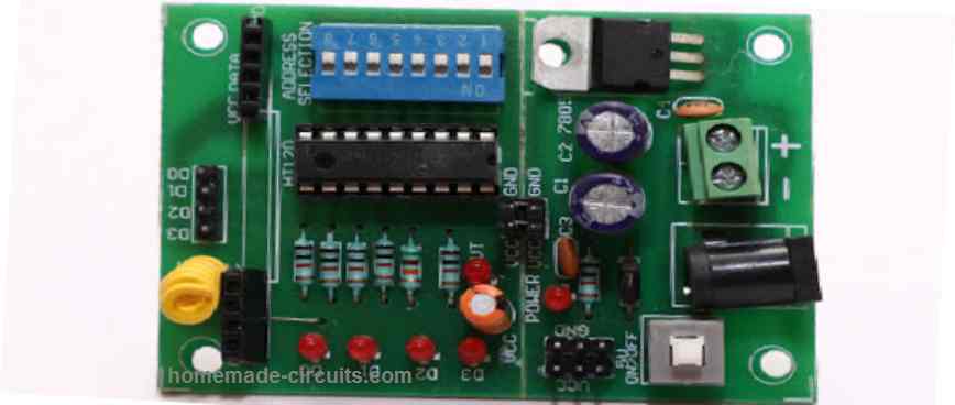
RF 315 MHz / 433 MHz Transmitter-receiver Module for Remote Control Application
Making your own universal remote control systems today is very easy.
Such procure the relevant chips, assemble them and here goes, your hi-tech remote control device is working for you.
Here we explain a couple of RF 433MHz remote control chips especially designed for the purpose.
The IC TWS-434 along with its encoder chip HOLTEK’s HT-12E form a high class transmitter circuit.
The chip RWS-434 through its complementing decoder IC HT-12D operates as the receiver module.
Both of the above modules are able to exchange 4-bits of discrete data for control four external loads separately.
With the easy availability of accurate remote control chips, making your own universal remote control modules is today just a matter of few hours.
We discuss a couple of compact RF remote control transmitter and receiver modules here using the chips: HT-12E, HT-12D, TWS-434, RWS-434
Making a hi-end professional remote control system at home is a child’s play now. With the advent of micro remote control encoder and decoders chips, making a RF remote control is today a matter of a few hours or rather minutes.
Applications of remote controls made from these chips are countless; you may use it for controlling practically any electrical gadget that you can think of, the best application being for car security systems.
TWS-434 and RWS-434
A couple of RF remote control chips, the TWS-434 and the RWS-434 both complement each other, the first one being the transmitter and the later one the receiver.
The chip TWS-434 is basically a tiny 4-bit transmitter module, which is able to transmit 4 types of coded signals discretely, whereas the RWS-434 exactly complements these signals by receiving them and generating 4 discrete decoded signals at its outputs.
However both the above primarily functions just as wireless sender and receiver and therefore require external encoders and decoders to be integrated for the said operations.
Understanding the 433MHz RF Transmitter Module Pinouts
A couple of HOLTEK’s encoder and decoder chips HT-12E and HT-12D work in conjunction with TWS-434 and RWS-434 respectively to produce the desired ideal universal remote control operating parameters.
Referring to the diagram alongside, we find a straightforward RF transmitter configuration using the chip TWS-434 and HT-12E.
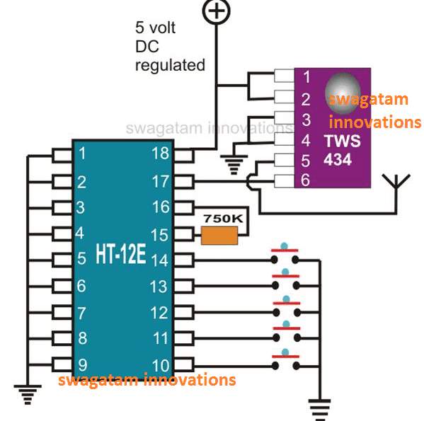
The IC TWS-434 has in all 6 pin outs, 1 and 2 are the positive inputs, 3 and 4 are to be grounded, 6 receives the 4-bit encoded signals, pin 5 being the antenna for radiating the received signals.
The pinout details of the RF transmitter as shown in the above diagram may be understood as follows:
The 4-bit encoding is done by the IC HT-12E.
The wiring of this IC is also very simple; all its 1 to 9 pin-outs are shorted together to ground and these refer to the address pinouts of the IC.
These 1 to 9 address pins can be configured differently as desired to generate a variety of different encoded messages from the transmitter.
For example, you can leave a 1 to 4 pins unconnected and connect the remaining pins to ground, this will produce a differently encoded output signals which will be completely different from the one where all the pins are connected to ground.
In this way you can generate many different sets of unique configurations by selecting any desired 1 to 9 pins either left open or connected to ground.
Thus, you can create different variations with these 1 to 9 pins, some of them connected to ground and some of them not connected to ground, or all of them connected to ground.
Remember, the connection pattern created across pins 1 to 9 in the transmitter circuit must be exactly replicated in the receiver circuit, otherwise the two units will not be compatible and will fail to work together.
Pin 16 and 15 are coupled to each other through a 750 K resistor.
Pinouts 10, 11, 12, 13, all receive 4 discrete data simply through the connections of the respective pins to ground via a push button switch.
Pin 14 confirms switching of the transmitter signals when connected to ground via another push button.
Pin 17 is the output and conveys the processed 4-bit ata to the IC TWS-434 for the final relay. Pin 18 is for the positive supply input
Understanding the 433MHz RF Receiver Module Pinouts
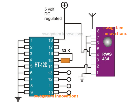
The diagram alongside shows a similar configuration to the above, but with exactly the opposite transits.
The pinout specifications for the RF receiver module as shown above may be understood from the following explanation:
Here, the chip RWS-434,s antenna receive the data transmitted by the above transmitter module and sends it to the IC HT-12D for the necessary decoding of the 4-bit data which ultimately is decoded and produced at the respective outputs for driving the connected loads.
Understanding the pin-outs of the IC RSW-434 is pretty simple, pin 1, 6 and 7 are all shorted to ground.
Pin 4, 5 go to the positive supply.
Pin 2 outputs the received data to the decoder IC and pin 8 serves as the antenna.
The decoder chip HT-12D has its entire pin from 1 to 9 fixed to the ground potential.
Pin 15 is connected to 16 through a 33 K resistor as per its specs.
Pin 14 receives the information received by RSW-434 and after decoding the processed data is obtained from the pins 10, 11, 12, 13 respectively, which is further fed to the output driving circuit for activating the connected gadgets.
Both the modules of the above universal remote control work satisfactorily through a regulated 5 volt power supply unit.
If you have any specific questions regarding the pinouts of the above explained 433 MHz RF transmitter and receiver modules please feel free to ask them through your comments.


Discussion & Solutions
the outputs are four only, the extra pins are unused or are shorted.
Will it be secure what if another person would build the same circuit will that person be able to control the output What can i do to make more personalize like the remote for the car alarm. Can i used a dual tone multiple frequency encoder decoder with the transmitter
The possibility can be eliminated by configuring the address pins uniquely for the particular Rx/Tx sets.
Suppose you disconnect all the address pins A1 to A10 of the Rx module and select A1 and A2 only for the ground connections, and you do the same with the Tx module….this will make the two unit compatible and paired with each other uniquely and will not respond to other modules in the vicinity which could have a different address pin configuration.
In this way you can select different sets of address pins and group them with each other or with ground (identically for both the modules) for creating unique pairs.
Thank you
Hi, I'm making a similar circuit but I have a little problem I bought two pairs of the rf circuits, I mean 2 transmitter and 2 receiver in order to have 8 devices to controlled, but when I did the first circuits (receiver and transmitter) they worked properly, but when I did another pair of circuits (receiver and transmitter), the first circuits stop working, actually they work if I don't connect the second circuits and the second circuits work if I don't connect the first circuits, what could I do?, both circuits have a different address
Hi, It's difficult to figure out, they might be operating with the same frequencies but in that case all should have worked randomly irrespective of whether remote#1 or remote#2 is being used, but in your case one is blocking the other, I have played with many such circuits but haven't faced this problem yet, so really can't troubleshoot the issue.
could I change the frequency? , both remotes are in 434Mhz frequency
yes, you can try doing it if you know how to it.
Dear sir..may I know which software did you use to make schematic circuit? I always use proteus..but some components are not available in that software..and I want to run a circuit simulation..please help me again..thank you and waiting for your reply soon..:)
Dear Akmar, I usually simulate the circuits in my mind, I don't use any software, so not sure about them.
hy…according to your circuit in the receiver side,data pins (10-13) are having high voltage initially and get connects to ground wen push button is pressed..but my data pins are having low voltage(0.43V)initially..is there anything with the push button connection??
hi, I can't see where I mentioned this??
anyway, if the pins are low initially and become high on pressing the Tx buttons then it's fine too…you can configure the output stage accordingly.
Hi Sir.
I am boy who has very keen interest in Electronics and Circuit making. Seeing this project of yours, I wish to try this out. But I had also seen another post in which the circuits contains few additional and different connections, while the basic components remains the same as of this circuit. So wanted to know whether you had tested out this circuits and checked the proper functioning of this circuit, assuring 100% working.
This is the link to the other circuit—>>>
https://www.homemade-circuits.com/2013/07/simple-100-meter-rf-module-remote.html
Please Reply Soon
Anxiously waiting to try out this project 🙂
Thanks A Lot for sharing your hard works with all of Us 🙂
Hi Jibin, the circuit has been tested by a few of the readers from this blog and they could successfully implement the results, these circuits have become very common and reliable nowadays and it's not at all difficult to work with these chips…
Hi swagatam, nice tutorial on RF encoders and decoders.BTW, How HT12E/D can successfully communicate using 433 mhz rf modules did you know how they works? with PIC micro controller its very hard , maybe the working principle of these encoders or decoders is secret…
Thanks Mrunal, the internal circuitry could be extremely complex and intricate, so yes replicating these modules using PIC won't be easy, at least at our level.
swagatam ji i m using RF 434 receiver and transmitter.
i m using 16 inches radio antenna.
transmitter voltage 6 v
and receiver voltage 5 v DC.
range is 60 feets in home condition.
if i increase transmitter volt 9-12 volt
range not increase.
i need 500 feet range.
how can i got it.
Prashant ji, you can try increasing the antenna length a little more by using any ordinary flexible wire, may be around a 2 meter length, that's the only thing you can try….there's no other option to enhance the range….since it's rated with a range not more than 50 to 70 meters.
increasing voltage will not help
swagatam ji here is a problem
i m using RF 434 with ht 12 e and ht12d
i m using in home.
i have a door lock in in home woth help of car centeral lock remote.
here is problem if RF receiver is on car cennetal lock range getting to low.
if i switch off transmitter 434
then centetal lock range goes high.
please solution for it .
i m using in address ( no sjort with -ve to pin 12345678.
plz tell me if i change the adress with dip switch frequency change or data address change ?
thanx n happy holi.
prashant ji, yes matching the transmitter module's address connections with the receiver module's address connections will make them compatible with each other…..so you can try this through a SPDT switch.
Sir address bhe change kr diye hai rf434 ke.
But prob same hai.
Hi sir
I’m interested in your article and try to do this.
But I don’t know more about electric components and how it can be mentioned to a retailer.
So please help me.add images too if possible
Thank you
Hi Akhil,
You just have to write down the numbers which are shown on the IC, and the resistor numbers which are shown beside the resistors. The resistors are rated at 1/4 w 5%.
additionally there are 5 push button switches, which you can also mention in the list.
Thank you
hello sir what different in 434mhz rws and tws and ask module can i send audio by rf module
hardev, you will have to use two classD amplifiers, one will convert analogue audio to pwm pulses, these pwm pules can be fed to a 433 MHz Tx unit and then received back on a 433MHz Rx then decoded back to audio through another classD amplifier
Hello sir, I want to make wireless water level controller and indicator & automatic ON OFF Pump using Rf 433, Ic 7408, 7414, ht12e & d.
Can you help me
Hello Md Faisal, you can try investigating the circuits explained in the following page:
https://www.homemade-circuits.com/?s=remote+water
Hi, thanks for the post!
I think this is what I need, however can it be simplified?
Imagine the following… if I have a sensor attached to a magnet on the glass in a fish tank, with a corresponding magnet outside, when the sensor sends the signal, i want to light an led on the magnet outside the tank.
Hi, I don’t think a RF transmitter would be required for this simple procedure? You can use infra red transmitter or receiver for implementing the same….by the way what is role of the magnets on both sides? and what would trigger the sensors??
Hi. Thanks for the reply!
That sounds like a good idea. I don’t know much about electronics. I’m guessing I need a battery, a sensor and the transmitting switch on one magnet (wet side), and the battery, receiver switch and led/buzzer on the outside magnet. The magnets are just to hold the two together in the location I want. Thanks again.
OK thanks for the feedback, and for explaining the role of the magnet! Yes your assumptions are perfect regarding the assembly details of the sensor and the receiver!
Thanks btw!!!
putting all the 8 pins in line and connecting wires — you call it a pin-out?
where is — which pin for what ? and by the way- there is no receiver unit available where all 8 pins are in one line! there are the bunches of 4 pins each sides and how can a reader get any value from what yu have put here in the name of the receiver pin out?
Read the article carefully. Those are address pinouts of the IC. You don’t have to connect all of them to ground. You can create different encoded outputs by connecting some of these pins to ground and keep some of them open or unconnected. Different connected and unconnected configurations will produce different sets of encoding which will be completely different to each other.
Sir good evening
It is amazing to see ur ideas on projects.the drone project plse tell me the size of the propeller for 4 motors and the motor available with your said specification 200ma current, 6 volts DC peak volts12
Raghu k chennai
Thank you Raghu, Glad you liked the projects, However, unfortunately I do not have the exact calculations regarding the propeller sizes and have no idea how to figure them out. I think an easy way could be to check the response through some trial and error.
Hello,I am a absolute beginner at this, Please can you help me, I have spent hours and hours at this (if not days) I have made a very simple fishing bite alarm..a buzzer and led ,a 9 volt battery and the switch is a reed switch which works when a magnet goes past it, simple, All I want to do is is put a 433 transmitter in there so that the signal will then go to a box in my pocket with a buzzer in it and the 433 receiver, it does not even have to have a long range, 30 ft will do……..I have bought about 10 of these sets and wired them up exactly as I have seen on u tube, (I have spent hours and hours watching them) I can not get them to work at all even when the units are right next to each other, I thought I would give it one more go today, …the receiver has a buzzer wired into it and as soon as I apply 4 volts it goes off on its on, without the transmitter telling it too, it only stops when the battery is dissed, any help please .
Hi, thanks for the question, I will try to help you?
Did you build the circuit using discrete components or did you buy readymade modules? How did you connect the buzzer to the receiver output? As far as I know, the outputs actually become “low” when a signal from the transmitter is detected. Therefore the buzzer must be connected between the positive line and the receiver output pin. If you connected the buzzer with the ground line then that may be wrong. However, in case you connected the buzzer between output and ground then buzzer should respond oppositely, it should stop buzzing when a signal is detected.
By the way the readymade modules have relays attached, do you have them in your modules?
I have myself worked with readymade transmitter/receiver modules and they have always worked flawlessly for me even from a distance of 20 meters.
Thank you for replying,, this is how it is wired, TRANSMITTER = positive from battery (12 volt) to VCC pin and negative to GROUND pin,then a switch ( micro switch or tactile switch ) from VCC pin to DATA pin, I have tried different lengths of ariels………………RECEIVER = 4 or 5 volt battery positive to VCC and negative to GROUND, then the positive leg of the LED or BUZZER is connected to VCC and the negative goes to the DATA pin, again different length copper ariel’s ,coiled and straight.,Thanks again for trying to help me , I am pulling my hair out
Are you sure the transmitter can work with 12V? I think the ICs are designed to work with 5V DC. If the buzzer is connected between the positive line and the data output pin then it is correct according to me. Not sure why your circuits are not working. It can be difficult to assess the fault without having a practical look at your circuits.
I have used many such modules in my experiments and all have worked perfectly, however all these modules were ready-made modules, I did not assemble them.
Thank you again for trying to help, I have tried batterys from 3 to 12 volts on the transmitter and 4 to 5 volts on the receivers, just as all the u tube videos have suggested, these are already made up units when I have bought them……….I have also bought at least 6 books on electronics and am even having trouble understanding them ! One of the books is Electronics for Dummys , is there a book out there that is easier than that one to understand ?I was really hoping you could help me with the transmitters/receivers as I have even tried some electronics forums to no avail, depending on your reply, I might just give it all up , no pressure.!!
I am afraid, if the transmitter or the receiver are designed to work with 5V then they may get destroyed at anything above 5V. I guess the ready made modules have a 7805 IC to regulate the 12V into 5V for the modules.
There’s one related post which was tested by one of the readers, you can refer to it in the following link:
https://www.homemade-circuits.com/simple-100-meter-rf-module-remote/
Electronics can be learned by gradually understanding and building small circuits. I have a few articles which involve small electronic circuits which you can read and build for mastering electronics, if you have problems you can always through, I will try to help
https://www.homemade-circuits.com/circuit-projects-for-beginners-and-school-students/
https://www.homemade-circuits.com/basic-electronic-circuits-explained-beginners-guide-to-electronics/
https://www.homemade-circuits.com/simple-hobby-circuits/
https://www.homemade-circuits.com/how-to-build-simple-transistor-circuits/
Thank you for not giving up on me, I will look at them links later on.
Sure, No problem!
Hello , Me again, I have looked at your links and done a couple of diagrams of the transmitter circuits, ( I have to have it on paper in front of me , like a book , old school ), I have referred back to my books to see what all the symbals are in the circuit, I have got a small bread board and am going to mess around with that instead of soldering things together, I am going to send off for a couple more of these 433 modules and have one more go at it, I really can not see what I have done wrong, all my attempt have been wired up correctly , exactly as in the u tube videos,I have got all the bits out again and when I connect 4 volts to the receiver, the buzzer sounds, even though I have no power to the transmitter, surely the buzzer should not sound until it receives a signal from the transmitter??
Hi, breadboard is strictly not recommended for these types of RF circuits, because even a small loose connection can cause the entire circuit to malfunction.
Also the ICs are designed to work with 5V so do not exceed this limit, preferably use a 7805 IC to regulate the voltage to 5V.
I would rather suggest you to buy ready-made tested modules, instead of assembling them yourself, that would save a lot of time and money for you.
Thank you, I do buy the ready made modules, That is what is so frustating, They are the 433 ones, all I have to do is a couple of connections and add the antenna’s and they should send and receive signals,If you could just advise me as to why the receiver (which has a buzzer wired onto it ) sounds when I connect a power supply of 5 volts to it , even when the transmitter has no power supply, how come the buzzer sounds ? , it is not getting a signal at all . If you could just answer this one last question for me I will leave you alone as I must be getting on your nerves by now,
The problem that you are facing should not happen on the first place. If the buzzer or the LED is connected between the positive and the data pin, it must remain shut off until a signal is received from the transmitter. If you have done all the connections correctly then it should not happen.
By ready-made units I mean units that are fully assembled with relays, which does not require any extra connections, such as this one:
These modules will always work without fail.
Thank you for patience, you have helped me more than anyone else did.