A term MEG refers to motionless electromagnetic generator circuit which is designed to generate electrical energy without using any moving components or involving any kind of mechanical stages.
How a MEG Device Woks
The device is made solely through a strategic placement and interaction of permanent magnets, coils and a ferromagnetic core. The specialty of this device as claimed by the inventors and researchers lies in its potential to generate an output power much higher than the induced input triggering power.
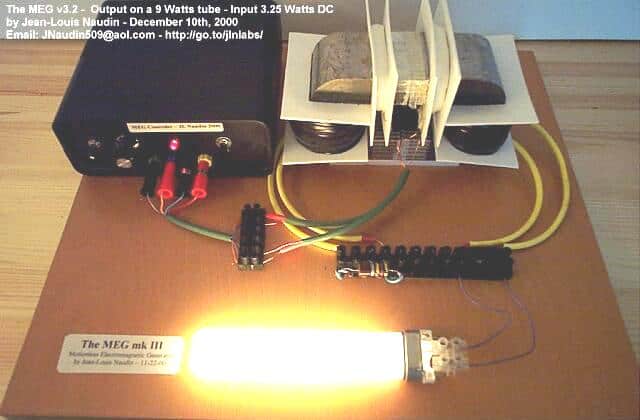
A MEG device comprises of a couple of winding sections wherein the first input and the output inductors operate along the regions of the first magnetic path, while the second input and output inductors operate along regions of the second magnetic path.
To execute the above function, the input coils are alternately agitated through an external pulsating DC, so that the back EMF from the input coils are able to induce an identical pulsating current over the secondary coils at a specified magnitude and rate.
This magnitude of output power as measured by the inventors show outstanding enhancement by a factor of COP 3.
COP is the abbreviation for coefficient of performance, and a COP 3 overunity means an output power that's 3 time more than the input power..... it's like getting 3 watts from an input power of only 1 watt.
If we examine the proposed MEG device we realize that it's actually not violating any law of thermodynamics. The secret behind the increase in the COP value is due to the smart application of the coils and the permanent magnets, and their interaction with the central ferromagnetic core.
In one of my earlier posts I have explained about the parallel path magnetic device and learned how a small electrical pulse applied externally to its coils is able to channelize the power of the permanent magnets towards the relevant edges of the device generating immense magnetic force over those ends, and this immense concentrated magnetic force was as high as 4 times more than the capability of the input power.
The proposed motionless electromagnetic generator circuit exploits the same principle, by mobilizing the dormant stored power of the permanent magnets for generating electrical energy much higher than the applied input triggering pulses.
Basic Coil and Magnet Layout Set up for a MEG device
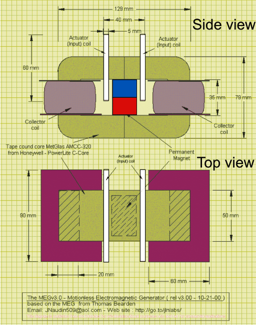
The figure above shows the basic layout or set up of the coils, magnets and the core. The green colored section indicates the ferromagnetic core, which are in the form of 2 C-cores joined edge to edge, like this [ ].
The violet colored items are the collector coils wound over plastic bobbins, these coils react with accumulated, concentrated pulsating magnetic fields and convert them into COP3 electrical energy or COP 3 overunity output.
The white sections indicate the smaller trigger coils which accept the pulsating DC input from an external power supply source.
The central red, blue blocks refer to the magnets which should be preferably neodymium types.
In the image the upper drawing shows the side view of the device while the lower diagram presents the top view of the ME Generator.
The coils indicated in white are required to be pulsated alternately at some specified frequency which could be according to the core specification.
For laminated iron C-cores, the frequency could be anywhere between 50 and 200Hz, this might need some experimentation for figuring out the optimal or the most beneficial outcome, in terms of the COP value.
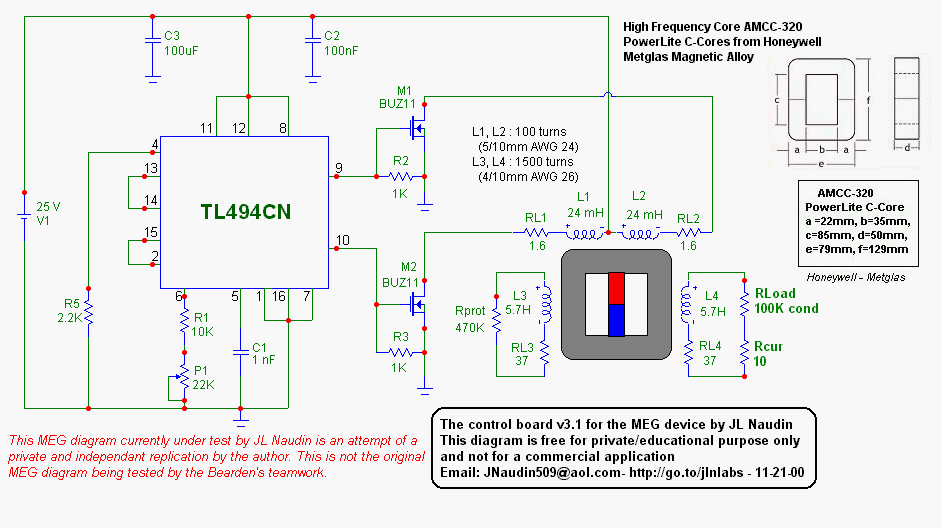
The following circuit diagram can be effectively used for powering the primary coils, as stated in the above paragraph.
Core Specifications:
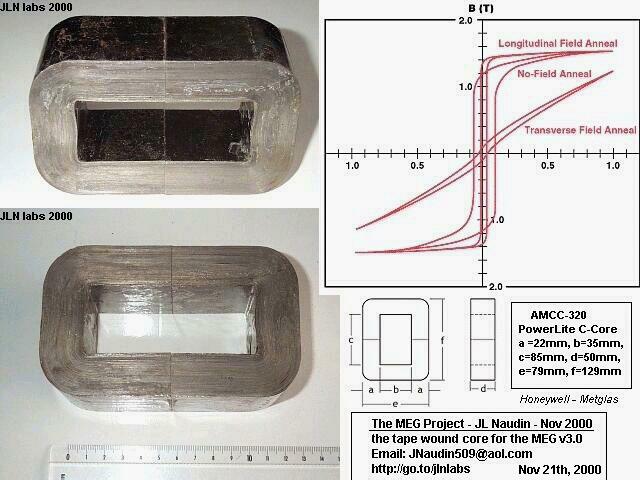
The core used for the MEG can be crucial, the details are furnished in the following image:
Inventors: Patrick Stephen L; Bearden Thomas E.; Hayes James C.; Moore Kenneth D.; Kenny James L.
Appl. No.:656313 Filed:September 6, 2000


Questions & Answers
Hello does the pm flux with this circuit arrangement work at 50hz
No, the PM flux does not naturally work at 50Hz. The permanent magnet flux is static (DC magnetic field), it has no frequency of its own. It only starts to respond dynamically when you apply a pulsed input through the drive coils.
If you apply a 50Hz pulsed input to the control coils, then yes the flux inside the core will shift or swing back and forth at 50Hz. That movement causes induction in the output coils, just like a transformer with no moving parts.
by increasing the size of iron core and adding more magnets can it produce 2kw of electrical energy???
please reply..
I am not so sure about it. It will need to be experimented.
First, we have to check whether the above basic design works correctly or not, if it works then we can slowly upgrade it according our needs.
what’s the maximum rating of the Meg ????
can it produces 2kw energy from single Meg???
The maximum power could be around 60 watts, 2kW may not be feasible.
Hi, I built this MEG device, I believe I got it to work as intended. The key is to use a non linear load. Any tests with a linear load such as a resistor will not show over unity.
Next is to find a way to use that output for something useful like powering the MEG device. To date, I do not know if anyone was able to do so.
Hi, thanks so much for updating the results! This sounds fantastic. Please let us know if there are any further developments.
Motionless Electromagnetic Generator
https://patents.google.com/patent/US6362718B1/en
The Motionless Electromagnetic Generator operates in accordance with an extension of Faraday’s Law, indicating that an electrical current is induced within a conductor within a changing magnetic field, even if the source of the magnetic field is stationary.
How does the MEG work?
Consider the physical layout of the MEG. You have a stack of neodymium magnets in the center of a rectangular toroidal core. The magnets touch each side of the core on the inside. There are no coils on the core yet.
What does the magnet flux do?
The flux from the magnets will divide equally between each leg of the core. So you have half the flux flowing on the right and half on the left.
You now place coils on this core. You use two control coils on the top on each side of the magnet stack. And you wind two output coils on each vertical leg on opposite sides.
OK, it is set up. Now you want to switch all the magnet flux to one side by opposing the magnet flux with the opposite control coil. How much flux will the coil need to generate to do this? Well, the answer of course is half the magnet flux since that is what is flowing in that leg. The other control coil is in the off condition, and open circuited, so no current can be induced in it and hence no back-flux generated. The core must not be allowed to reach magnetic saturation or more energy will be required to force the flux to the other side.
Then you turn off the control coil and what happens?
Remember both control coils are now off. The magnet flux will return to its original starting condition of half the flux flowing on each side. Does the magnet need any help to do this? No, of course not. When you did this you also removed half the magnet flux from the other leg when the control coil was on. The first half cycle you only see half the normal induction level in each output coil because at the start you only switch half the magnet flux into one leg and out of the other. So the total change is Bmag/2.
Now on subsequent cycles you let the magnet flux return to its original steady state and let the magnet do the work. Both control coils are off while this happens. Just when the magnet flux reaches its equilibrium point you turn on the other coil and keep the flux change going the other way. Each coil only needs to always switch half the magnet flux not all of it. After the first half cycle you see a 100% change of the magnet flux in each output coil on each cycle for an input power that is half the output. This assumes that you are activating the control coils for half of each cycle. This means you have a theoretical maximum COP of 2.0. You are using the magnet stack as a flux battery and “letting” it do half the work.
So you can get an OverUnity solid state generator with a theoretical maximum gain of 2.0. Just this alone could allow you to reduce your utility bill by about half if you put these devices between your breaker panel and your appliances.
Built a rotoverter.
Please explain more!
Is there a commercially available version of this device.
Hello Swagatam, Thank you for this. I was wondering if you might put me in touch with anyone who has got this to work. The poster “Cycle” did quite a lot of work back in May-June2020. Do you know if he got this to work or how to get in touch with him? We live in some interesting times, and anything potentially good, I would like to support.
Thank you Steve,
I don’t seem to find anybody you has successfully tested and verified the working of the above concept. I have no further information whether Cycle was able to build and confirm the MEG circuit successfully or not. I think if you search on youtube you could find something related with confirmed test results.
Thank you Swagatam for posting this. If you’re interested in actually replication this device please let me know. Would love to discuss.
Thank you John, it would be indeed great if you replicate this project and update the details here. The other visitors here would surely love to read it.
Dear Swagatan,
I am currently in the process of buying all of the components for this.
What’s the wattage rating for the Resistors and Capacitors?
What does P1 stand for and what is the power rating on it?
Thank you so much!
Hi Ryan,
Glad to know you are about to try this circuit.
All the resistors are 1/4 watt 5% But I am not sure about RL1, RL2, RL3, RL4 you can try 2 watt resistors for them.
P1 is variable resistor, also known as a preset or a trimpot. It can be any standard type.
I did not get a notification, but I had this left open on my computer.
Thank you so much for the reply! I will give it a shot!
Sure, no problem.
Let me know if you receive a notification for this reply.
Hi…I’m just getting into this rabbit hole of radiant energy devices, and this MEG unit is intriguing. My questions are: What components are needed to keep from shorting out a battery/power supply, to get current to a wire coil over a ring magnet? There is also a Caduceus style winding around the magnet-coil ring. The photo of the unit I saw had a 4AA batt pack (5v.) to kick start the windings, but the circuitry was not explained quite enough for me to get it. It had a regular wall outlet connected to the output side where they were getting a 749v. reading on the meter. If you are interested in discussing this or to see a photo of what I have so far, I’m very interested in learning the electric side of things. I am a machinist by trade and can follow descriptions. I just need some help with this circuitry. Thanks…Your articles on here are really helping me understand more about this.
Hi Jesse,
I have some technical data from another engineer that had posted and worked on replicating this device. Feel free to reach out to me via email, am happy to collaborate, jwrare@gmail.com
Hi, thanks you, and glad you liked the articles. I understand that you want to learn more about MEG, however due to work load and time constraints it can be difficult for me to delve into this subject and discuss it in details. Moreover I have never tested a radiant energy machine such as a MEG practically so my expertise is quite limited in this field of electronics
Thanks for your reply, and I understand, I’ll keep looking for something and if i find something I’ll post it back here.
Thank you, appreciate your response!
I have a question or concern. Why after over 20 years since this MEG patent, has there been NO working model available? In spite of the “claims” including J.Naudin who offered a COP of 3, I believe, early on. The crew that filed the patent seem to have no working model either. Yes, many have claimed an over-unity, but no one seems to have proof. Nor, has anyone offered a product in over two decades. The theory makes sense, yet here we are, with NO evidence that it works. I ran through and reviewed as many video experiments that I could find. In the end, they all just “faded” away, with no conclusions, lol. Any one here have more insight?
They only have a successful prototype. First the transfer functions of the device need to be calculated, then they can make a preproduction model and then they can start massproduction. To calculate the transfer functions is very difficult because you are trying to measure 1 signal in a VERY dens signal environment, you need special equipment and scientists to do this because your average electric engineering PhD is not able to do this. You can find the necessary people and equipment but this is very expensive. Now the meg team is trying to find some risk venture capitalist who will fund the project.
Hey Barry, good question. I became aware of this type of work via Dr. Steven Greer. He answers your question and has been involved with new energy tech since the early 90s.
I have not yet tested this circuit practically, so it will be difficult for me to suggest anything useful.
In their groundbreaking Motionless Electromagnetic Generator (MEG), they make use of something called the Aharonov-Bohm effect. It’s like a special trick they’ve patented. First, they use this effect to get the area around the transformer all charged up with what they call a curl-free A-potential. Then, they do some normal tweaking to the core, making it send out these A-field perturbations into that charged-up space outside (you know, into its A-potential). The MEG, in return, gets back extra energy in the form of pulses from the E-field, following a simple equation: dA/dt = – E. So, this altered space around the generator, when it gets tweaked again, gives back free E-field energy to the unit. It’s like a two-way exchange, with the local environment chipping in extra energy for free.
Now, when it comes to force fields, those are usually tied to matter because, well, mass plays a big role in it. But, when you’re in space without any mass, there’s no force, according to some smart folks like Richard Feynman. Instead, there’s this thing called “conditions of spacetime” going on, and what we casually call “EM force” is basically just how this spacetime thing interacts with charged stuff.
This dude John Wheeler, he had this cool saying about space and matter. He said, “Space tells matter how to move, and matter tells space how to curve.” Basically, they’re in this back-and-forth dance. Wheeler also threw some shade on elementary particles, saying they’re like a tiny blip in the big picture of vacuum physics.
The Aharonov-Bohm effect, along with some other cool tricks, shows that you can mess with the local spacetime directly. It’s like tweaking the very fabric of where things exist and then using it to influence what’s in that tweaked space.
So, when we say “force,” it’s not some magical thing. It’s just how spacetime conditions chat it up with charged matter. The big takeaway here is that they’ve figured out a way to prep the space around their generator without doing any heavy lifting or using force. Then, they give this energized space a little nudge, and it happily gives back extra energy to power things up. It’s like having two sources of energy: one you put in to create the system and another the space around it chips in for free.
Now, these cool systems that go beyond the usual electrical engineering stuff were purposely left out of the game back in 1892. There was this whole thing about making things symmetrical, thanks to J. P. Morgan. They didn’t want asymmetrical “energy from the active vacuum” systems that Tesla had discovered to mess up their plans. Tesla, he had this dream of getting power from anywhere in the universe, but Morgan shut that down real quick. Instead, we got stuck with more regular power systems like AC.
Tesla was onto something big when he talked about machinery running on energy from everywhere. He wanted methods that didn’t waste any materials and could tap into never-ending stores of energy. Even back in the late 1800s, he believed we were close to making it happen. He envisioned engines running anywhere on Earth, fueled by the energy of the surroundings. Too bad his ideas got sidelined in favor of more traditional power systems.
Dear Swagatan,
I am an italian guy with passion for energy…
I would like to solve the problem of energy onboard of my saling boat, as I will live onboard next year…
I saw your meg, is it possible to realize a meg or similar generator of 500w 12v (maximum, I need less energy…)?
Is it possible to find it ready?
I am not be able to realize it… i think
Thank you for your answer
ciao
martino
Hi Martino, I appreciate your interest, and understand that you want to solve your onboard energy problem. However, I have not yet verified the above concept practically, so I can’t actually confirm whether the above circuit really works or not. Therefore it is presently difficult for me to solve your query, I hope somebody else might know more about this concept and help you out with your requirement.
The Motionless Electromagnetic Generator: How It Works.
http://www.rexresearch.com/bearden/BeardenMEGHowworks.doc
EXPLANATION OF THE MOTIONLESS ELECTROMAGNETIC GENERATOR WITH 0(3)
ELECTRODYNAMICS.
http://www.rexresearch.com/bearden/BeardenEXPLANATIONMEG.pdf
Hi Swagatam
My name is Tom Kenefick.
I live in Missouri USA
I saw your circuit that generates motionless high power 110/220 volts AC.
I tried to save it but that did not work.
I would like to power my house to get off the grid.
What is the name or number of your high power generator?
I have seen a lot of generators on the internet but they don’t have the how to details.
Hi Swagatam,
As I recall it had a bank of about a dozen light bulbs in the back.
In front there were 3 coils with one slid inside the large one.
It made high power 110 and 220 volts that I want to use to power my house to cut my electric bill or get off the grid.
It is all solid state/motionless.
I don’t think it used a transformer.
Thank You
Tom Kenefck
gtomkx@gmail .com
Hi Tom,
Are you referring to the following article?
https://www.homemade-circuits.com/5kva-ferrite-core-inverter-circuit/
Hi Tom,
sorry, can’t remember which circuit you are referring to? There are more than 1300 posts in this blog, so I may have completely forgotten about the one you are looking for….could you provide more specifications of the generator so that I can remember its location?
Do you know of anyone anywhere who can make an MEG with a COP of 3?
Sorry, I do not have anybody who would do this practically….
What are the Voltage, current and power ratings for the MEG as built? Can the MEG be upsized for typical household volatge and current? How is this done?
It will depend on the coil wire dimension. I am not sure how it can be upgraded, so can’t confirm it.
It there someplace I can go to get more details? Have you built and tested a MEG? Do you know the Input and Output power limits? What application have you used a NEG for? Does anyone know more about this?
You can tweak it so as to produce so much power that you can burn the insulation of the wires
I have not tested this design. For more info you can check out the following link
http://citeseerx.ist.psu.edu/viewdoc/download?doi=10.1.1.129.6448&rep=rep1&type=pdf
Here’s a simplified circuit to prevent H-bridge shoot-through… the transistor goes foward-active when there is voltage on the H-bridge. Normally, this would be when the pulse voltage to drive the MOSFET gates is off… except during shoot-through. In that situation, the bottom MOSFET dumps voltage off the gates of the two transistors feeding voltage to the H-bridge lower MOSFET gate, preventing shoot-through.
Open both switches to simulate shoot-through without shoot-through protection. Close the bottom switch to activate shoot-through protection.
The 25 kOhm potentiometer is adjusted to give a gate voltage just below the MOSFET’s threshold, so when shoot-through protection is activated, the lower H-bridge MOSFET will not close.
http://tinyurl.com/y94vlsr8
As regards H-bridge shoot-through, I think I’ve found a solution…
http://tinyurl.com/ydyk8urt
In the circuit simulator, hit the “Run / Stop” button (if it doesn’t start running automatically upon page-load).
The top switch is open, simulating the upper MOSFET being closed even when the lower MOSFET is closed… ie: we’re force-simulating shoot-through.
Note the peak amperage on the graph to the right… 861.796 mA when the lower right-hand MOSFET closes. The lower right-hand MOSFET (which would be a part of the H-bridge) is dumping 861.769 mA during this shoot-through event.
Now close the bottom switch. Note that the left-hand MOSFET (the probe-MOSFET, a part of the protective circuitry) is now dumping ~722 nA (average) to ground… that’s the amount of current we have to ‘throw away’ to get the protective circuitry to work properly.
Note that the right-hand MOSFET is now dumping ~2.9 mA (average) to ground… this represents the amount of shoot-through with the protective circuitry in operation. So we’ve lowered the shoot-through by ~858 mA.
Now close the top switch (simulating normal operation)… note that the Vgs (Voltage: Gate To Source) of the lower MOSFETs is 11.936 V (for the protection MOSFET) and 11.988 V (for the lower right-hand MOSFET)… so the protection circuitry only scrubs off 0.064 V and 0.012 V from the gate voltages as compare to if the MOSFETs were driven directly.
Note also that during normal operation, the protective circuitry dumps ~201 nA to ground… that is the ‘cost’ we pay to protect from shoot-through.
I’m sure the circuit can be further improved to lower that ‘cost’. I’ll keep working on it.