In this post I have explained an over unity generator set up using two motors and an inverter for getting a sustained free energy infinitely. The idea was suggested by Mr. Dare.
Technical Specifications
I came across your website when searching for on Google, alternator booster which helps small Genset of 650W to bear load more than there capacity.
Please, I need your assistance.
I want to build an over unity electric power generator of 12VDC output by using 1 DC motor generator that is said to generate up to 150V/2A at 3000RPM and One DC Motor.
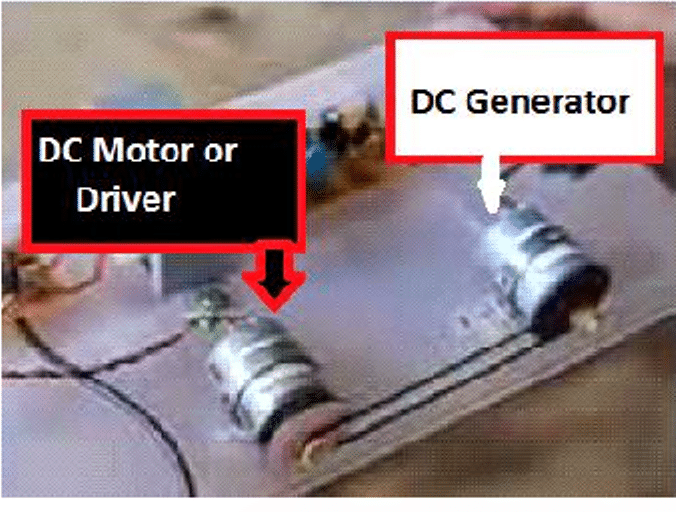
One of the Motors will be driving the other while the other one will be generating the voltage as it is being driven by the other as seen below.
Analyzing the Overunity Circuit Concept
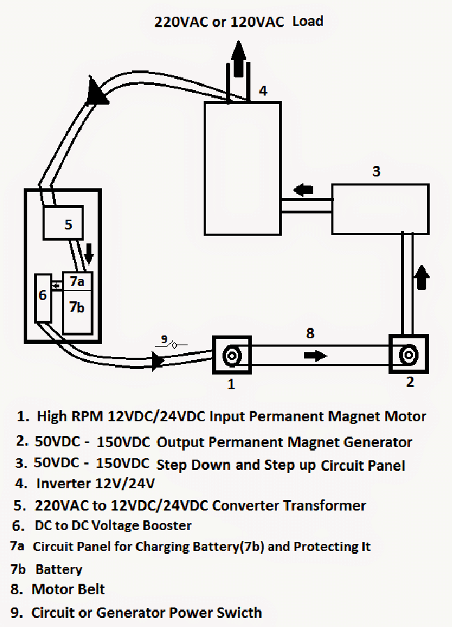
Now in the diagram above Sir, once the switch (9) is on, the part I numbered 1 (motor) will be driving the part I numbered 2 (generator).
The generator will be generating high voltage and sending it to part numbered 3 which is an integrated DC to DC step down and Step-Up Power Circuit and load bearer.
The Power Circuit would step-down the incoming upward of 100VDC to 12VDC or 24VDC but step-up the Amps from the incoming less than 2A to upward of 30A.
So assuming the final output voltage is 12V/30A then it will further it to the part labeled 4 which is the Inverter. The inverter will both supply the house and simultaneously supply the AC to DC transformer which I numbered 5. The AC to DC will convert the incoming voltage of 220VAC or 120VAC to 24VDC.
The 24VDC from the transformer will enter the part numbered 7a. The part numbered 7a will supply voltage to the part numbered 7b which is the battery.
The Battery which will be Lithium Polymer battery of 22.2V (Six 3.7V batteries connected in Series) will be getting constantly charged by 24VDC from the Circuit Panel numbered 7a. While at the same time be getting discharged at 10VDC/5A through 7a.
Furthermore the part I numbered 7a will function as, Battery over charge protector, over discharge protector, and continuous further power supply to the part I numbered 6 which again is the Voltage Booster that will be receiving 10VDC/5A from 7ab and Step it up to 24VDC which will further be supplied to the Driving Motor which is numbered 1 in the diagram above.
The Battery function is to act as a standby power on for the generator.
The intermediate switch which I numbered 9 between the protected battery and the Motor or Driver is the bridge. It allows for switching on and off the Generator when one wish.
From the Driving Motor, the cycle begins again.
Questions and Answers Regarding the above Free Energy Concept
Now, I please need your guidance as follows:
1: Will it be better to use a DC Generator that can generate directly lesser
Voltage but Higher amps (e.g 35V/15A)??
Ans: A DC generator will work better, as these are designed specifically for generating electricity.
2. What kind of Motor and Generator will work best? Permanent Magnet Brushed or Permanent Magnet Brushless?
Ans: Permanent Magnet brushless type is recommended.
3. In my design above, the inverter will not be receiving input voltage from a battery but instead from the earlier mentioned integrated DC to DC step down and Step-Up Power Circuit and load bearer (600W). Is this possible?
Ans: Yes the inverter will work equally well with it as long as the input is well filtered into a clean DC.
4. Does an inverter act as load too? If yes, how do I calculate the load of an inverter that is rated 500W load bearer or 500W output power? I mean if an inverter can bear a load of say 500W, what will be the load that such inverter will mount on any device that generates DC voltage of 12VDC or 24VDC.
Ans: Inverter will not act as a load but will surely introduce some losses, may be 10% or 20% depending on the quality or the topology used
5. What is the general minimum and maximum required Amp of an inverter before it can work? Will an Inverter works even if it receives say 12VDC/2A or 24VDC/2A input power?
Ans: Yes, the minimum amp will be actually the minimum amp at which the devices turn ON which may be in milliamps, so this issue can be negligible and can be ignored.
6. In my own layman knowledge, I think constantly charging the battery of 22.2VDC/2.6A with 24VDC and discharging it to 10V/5A will not make the battery run-out of power. May I know if this is correct?
Ans: Charging it with 24 V is OK, but discharging it to 10 V will surely damage the battery very soon
7. If not, please how can I make sure the battery does not run out of power and thereby cause the system to stop working at any time it is switch on?
Ans: Do not allow the battery to discharge below 21 V
8. Is it possible to use Super Capacitor in place of the batteries as they will be getting charged quicker more than the battery?
Ans: Yes it may be tried along with the Lipo battery, alone these may not be so effective
I Hope to receive your reply soonest.
Best regards.
Warning: The above concept looks fascinating but practically it will never work.


Questions & Answers
Hi. Mr Swagatam plz send me details of overunity free energy generator using 2 motors.i wanna make it. Plz send its details to my email: nsgooya@yahoo.com
Hi Sami, the details are provided in the above article, i do not have anymore than this at the moment….
this concept is just to provide you just a simple knowledge.
and will work.
eg. take motor(2) in the diagram as a wind-turbine ( where there's no wind to spin there is no power generated out)
now take motor (1) as the wind blowing which is spinning the turbine (motor 2) power is generated
and with(3) power/current out from (2) is controlled and regulated for (4)
this will work nice as long as motor (1) spin and rotate motor (2)
note: this can not be simply understood by shallow minders you'v got to have some skill to understand things well so keep studying on this site for more knowledge.
don't make a mockery of yourself…..
Good Post Swag.
Stay Blessed.
Can u send me also the diagram. What will i do if i want to change the transformer to make it handy. Because i want to use it when im traveling. Tnx in advance
Generator Using two Motors this dayagram and part plz
may gmail jayhsreevideo37@gmail.com
you don't know too much i can see ! spammer well glad you think so ! mr think you know it all ! well guess what! you don't !!
swagatam !! man you are soooo wrong ! i've made 4 of these and all 4 produce much overunity ! what is wrong with you ? is your mind warping or what ! ?? you actually don't know too much !! i can see !!
OK please send the info to
admin @ http://www.homemade-circuits.com
don't make a mockery of yourself….only spammers talk like you.
overunity using two motors as explained above can never happen unless done with some extremely special technology.
thanks mr. Swagatam. just today i found this site. it is better then best.
Thanks, you are most welcome!
The main reason why this set-up can't work is that the Motor used as Generator is as well made with thin Gauge enmeeled copper wire!
The secrete to achieving over-unity using readymade low voltage motors is to use the ready-made motor to drive Permanent Magnet Alternator made with thick Gauge Coated Copper Wire like AWG #14. The best way to go making the P.M.G or P.M.A is to use Split Stator and Cardboard Rotor.
When you use carboard to house the Magnets it reduces the overall weigth of the Rotor+shaft. Also, when you use thick coated copper wire of say 1.8mm and above, little Torque and speed will bé needed to generate High Wattage Output. Make sure your magnets are N52 or N48 rated Neodymium magnets. High Farad Super capacitors works well with readymade brushless Motors that uses low Power.
Hi Dare pls i want to know if you have done this project and can you pls assist me with details so i can make one as-well
Akintunde, yes I did it the way I originally planned it but it did not work. But now it will work if Resonance is brought into the set-up.
Lenz is overunity road block.
I want all you reader of Mr.Swagatam Majumdar to know that it is better go for Motionless Lenzles s system.
I Dare Diamond is a Builder so do not think I am giving you all theories.
However, I am not that good in Electronics. But mechanically, I am Firing like Kilode!! No I am not bragging. Iron sharpens Iron so What I have not others like S.Majumdar and co would have. This is why I do come here for help when Electronics comes into play.
Now, please everyone should make an NE555 Oscillator with independently adjustable frequency and Duty Cycle. That’s your NE555 Oscillator frequency when being adjusted must not affect the duty cycle and vice-versa. I belief unlike me, everyone on here Know how to Properly configure that as I am using a readymade one I bought and it does not have the feature I ask you all to implement in your design.
Here is a page >> https://www.google.com/search?q=NE555+adjust+the+mark+space+ratio+separately&client=ucweb-b&channel=sb you can get ideas from.
Assuming you have make the said Oscillator, cut two 1mm thick magnet wire of 980inches i.e 81feet 8inches long. So you need 2 of the 980inches long of 1mm wire.
Divide in of the wires into two equal lengths.
Get a PVC Pipe of say 50mm or whichever size you can get and wind the equally divided length side by side in same direction. I.E, you start clockwise with the first, and start clockwise with the second too.
Dare, I appreciate your response but please to not endorse any online store or link. Presently I have removed all the affiliate links that you had inserted in your comment.
Thanks for your feedback Dare, I appreciate your honest response, however an over-unitymotor is NEVER possible, unless something extremely unusual is developed, such as the SCG motor which is based on a highly innovative "Space Charge" concept….