• Skip to main content
  • Skip to primary sidebar

Homemade Circuit Projects

Need circuit help? Post them in the comments! I've answered over 50,000!

Blog | Categories | About | Hire Me | Contact | Calculators-online
You are here: Home / Energy from Magnets and Earth / Parallel Path Overunity device

Parallel Path Overunity device

Last Updated on May 20, 2026 by Swagatam 17 Comments

In this post I have explained the making of a parallel path overunity device through a few magnets and coils.

Table of Contents
  • What is Parallel Path Technology
    • Building the Parallel Path Device
    • Applying Electricity to the Assembly
    • Attaining the 4X Overunity
      • Applying in Airplane Motors

What is Parallel Path Technology

Parallel path technology was first introduced by Mr. Joe Flynn and it's also called the Flynn's concept. In this concept or theory, a relatively weaker electromagnetic influence is used for aligning the magnetic fields of a few permanent magnets over a particular point enabling a massive force to generate over that particular side of the unit.

We know a lot about permanent magnets, and have seen how these natural power devices are able to stick or cling over ferromagnetic surfaces due to their inherent force of magnetic attraction.

However this property of magnets no matter how strong it may be have proved useless as far as the creation of perpetual energy is concerned or for devising overunity machines.

Very interestingly, Mr. Joe Flynn could devise a method through which it became possible to channelize the magnetic force of permanent magnets on particular directions with the help of a relatively smaller calculated electricity input.

Building the Parallel Path Device

The following paragraph explains the making of a parallel path over-unity device using ordinary electrical elements and a circuit:

Parallel path as the name suggests makes use of two parallel ferromagnetic plates arranged as shown in the following figure:
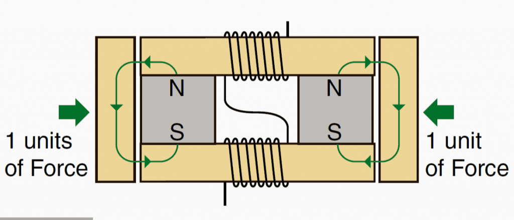
We can see a couple of horizontal plates sandwiching two permanent magnets between them at the ends.

Two vertical plates can also be seen positioned across the ends of the horizontal plates.

And the central vacant section of the horizontal plates possess coils of wire around them which are interconnected with each other and terminated for accepting an electrical potential or voltage.

Without any electricity applied to the coils, the vertical plates are subjected with a magnetic force of attraction that may be equal to the strength of the fields of the enclosed permanent magnets.

We can assume it to be unit 1 since the force is the fundamental force of attraction from the magnets and are equal on both the sides of the system.

Applying Electricity to the Assembly

Now, if a calculated magnitude of electricity is applied to the central coils, an amazing phenomenon could be seen happening, which is of course not so amazing rather more scientific and seems to be obeying the standard laws of magnetism........ yet you would find it very impressive.

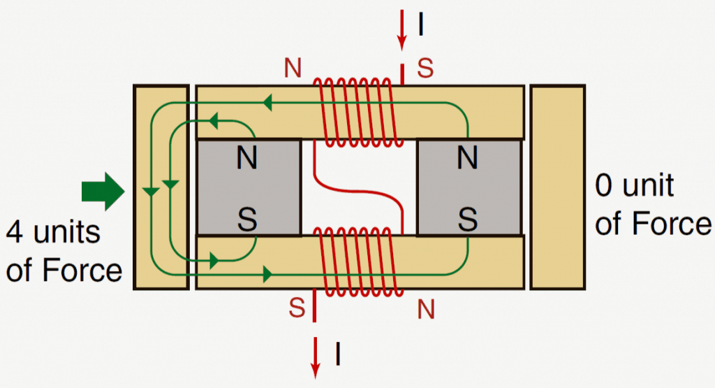
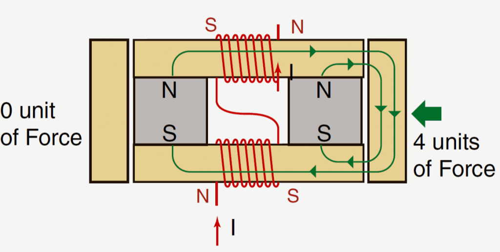
Depending on the polarity of the applied electricity, the magnetic lines of fluxes get aligned and neutralized on the particular sides of the plates respectively, generating a massive accumulation of magnetic force on one particular side, and zero force on the opposite side.

The above situation gets reversed as soon as the polarity of the electricity is reversed, as shown in the following figures.
Attaining the 4X Overunity

The most impressive and intriguing fact regarding the above implementation is the magnitude of force that is being achieved on the opposite sides, as shown in the above diagram it's 4 units on one side and zero on the other side.

It's proved that it takes the electric power of just 1 unit, that refers to the magnetic power of one enclosed magnet, to create the indicated 4 units of force.

Since the above actions can be flipped across the sides simply by flipping the polarity of the input electricity, we could be able to enforce the actions into a practical motion or a linear motion through some suitable mechanism, which would respond with 4 times more force than the conventional electromagnet operated devices.

The above theory looks absolutely feasible and have been tried out successfully by many enthusiasts.

Applying in Airplane Motors

Presently it's being tried for creating super efficient airplane motors.

Actually the applications could be diverse, it just needs an innovative smart approach for converting this concept into something which normally nobody would want to discuss openly...yes it's the overunity results which can be implemented using this theory, which looks quite obvious from the above theory.

If you have already made a parallel path device in your home, do let us know about its overunity results and additional benefits achieved through its specific applications

You'll also like:

  • coilforem 2Recover Energy from Induction Cooktop
  • bifilarcoilcircuitRecovering Electrical Energy from Alternator and Battery
  • gravity2BLED2Blamp2BcircuitMake this Gravity LED Lamp Circuit
  • EM panelFree 200 Volts Just Above your Head

Filed Under: Energy from Magnets and Earth Tagged With: device, Overunity, Parallel, Path

About Swagatam

I am an electronics engineer and doing practical hands-on work from more than 15 years now. Building real circuits, testing them and also making PCB layouts by myself. I really love doing all these things like inventing something new, designing electronics and also helping other people like hobby guys who want to make their own cool circuits at home.

And that is the main reason why I started this website homemade-circuits.com, to share different types of circuit ideas..

If you are having any kind of doubt or question related to circuits then just write down your question in the comment box below, I am like always checking, so I guarantee I will reply you for sure!

Previous Post: « Single Phase Voltage from Three Phase Voltage Source
Next Post: Inductors in AC/DC Circuits Explained »

Have a question or feedback? Feel free to ask below—just make sure it relates to the post above!

Subscribe
Notify of
guest
guest
17 Comments

Primary Sidebar

My YouTube Channel

Circuit Simulator: Draw and Simulate Schematics

circuit simulator image

Categories

  • Arduino Projects (95)
  • Audio and Amplifier Projects (134)
  • Automation Projects (18)
  • Automobile Electronics (104)
  • Battery Charger Circuits (90)
  • Datasheets and Components (109)
  • Electronics Theory (151)
  • Energy from Magnets and Earth (43)
  • Games and Sports Projects (11)
  • Grid and 3-Phase (20)
  • Health related Projects (27)
  • Home Electrical Circuits (13)
  • Indicator Circuits (16)
  • Inverter Circuits (98)
  • Lamps and Lights (161)
  • Meters and Testers (72)
  • Mini Projects (28)
  • Motor Controller (68)
  • Oscillator Circuits (30)
  • Pets and Pests (15)
  • Power Supply Circuits (91)
  • Remote Control Circuits (50)
  • Security and Alarm (65)
  • Sensors and Detectors (107)
  • SMPS and Converters (46)
  • Solar Controller Circuits (62)
  • Temperature Controllers (44)
  • Timer and Delay Relay (51)
  • Voltage Control and Protection (44)
  • Water Controller (37)
  • Wireless Circuits (31)

Subscribe to get New Circuits in your Email

Other Links

  • Privacy Policy
  • Cookie Policy
  • Disclaimer
  • Copyright
  • Videos
  • Sitemap

People also Search

555 Circuits | 741 Circuits | LM324 Circuits | LM338 Circuits | 4017 Circuits | Ultrasonic Projects | SMPS Projects | Christmas Projects | MOSFETs | Radio Circuits | Laser Circuits | PIR Projects |

Recent Comments

  • Swagatam on High Voltage Meter Circuit [for Measuring 10kV]
  • Swagatam on About Me
  • chukwuamaka on About Me
  • Brian Harding on High Voltage Meter Circuit [for Measuring 10kV]
  • Swagatam on Police/Ambulance Siren Circuit with Rotating Beacon Light

Social Profiles

  • Twitter
  • YouTube
  • Instagram
  • Pinterest
  • My Facebook-Page
  • Stack Exchange
  • Linkedin

Calculators

  • ZVS Induction Heater + Tank Calculator Tool
  • Zener Diode Calculator
  • Wire Current and Thickness Calculator (Ampacity Calculator)
  • Voltage Divider Calculator
  • Transistor Base Resistor Calculator
  • Transistor Astable Multivibrator Calculator
  • TL431 Calculator
  • Solar Panel, Inverter, Battery Calculator
  • Ferrite Core Air Gap Calculator Tool
  • Parallel MOSFET Calculator Tool: How to Connect MOSFETs in Parallel Safely
  • LC Resonance Calculator for EV Battery Charger Circuits
  • LED String Series Resistor Calculator
  • PFC (Power Factor Correction) Calculator Tool: 3kW
  • Passive Power Factor Correction (PFC) Calculator
  • LM567 IC Calculator Tool
  • SMPS Flyback Boost Converter Calculator
  • Shunt Resistor Calculator for Ammeters
  • SCR and Triac Gate Resistor Calculator
  • Battery Back up Time Calculator
  • Boost Converter Calculator (Non-Isolated)
  • Bootstrap Capacitor Calculator
  • Buck Converter Calculator
  • Buck-Boost Converter Calculator
  • Capacitance Reactance Calculator
  • DCM Flyback Transformer & Wire Gauge Wire Size Calculator Tool
  • Filter Capacitor Calculator
  • IC 4047 Calculator (Frequency and PWM)
  • IC 4060 Calculator
  • IC 555 Astable Calculator
  • IC 555 Monostable Calculator
  • IC SG3525, SG3524 Calculator
  • Inductance Calculator
  • Induction Heater Inductor and Resonant Frequency Calculator
  • Induction Heater Work Coil Calculator
  • Inverter LC Filter Calculator
  • LC Resonance Calculator
  • LED Current Calculator
  • LM317, LM338, LM396 Calculator
  • NAND/NOT Gate RC Values Calculator
  • NOT, NAND Gate Frequency Calculator
  • Notch Filter Calculator Tool
  • Ohm’s Law Calculator
  • Phase Angle Phase Shift Calculator
  • Power Factor (PF) Calculator
  • RC Filter Calculator
  • Reactance Calculator
  • Sine Table Calculator for SPWM Arduino Code
  • Small Signal Transistor(BJT) and Diode Quick Datasheet
  • SMPS Calculator for Toroidal Ferrite Transformers
  • SMPS Flyback Transformer Calculator – Design by Target Duty Cycle
  • TL431 Calculator
  • Op-Amp Hysteresis Resistor Calculator

© 2026 · Swagatam Innovations