The idea of acquiring free energy from induction cookwares using an external bifilar coil was suggested by one of the keen enthusiasts and a regular visitor of this blog. I have explained more regarding the details of this interesting free energy device, as explained by the author himself.
WARNING: THIS CONCEPT ATTEMPTS TO VIOLATE THE "LAW OF CONSERVATION OF ENERGY", SO ACCORDING TO ME IT CANNOT BE TRUE, TRY IT AT YOUR OWN RISK.
Generating Free Kilowatts from an Induction Cooktop
It was Tesla who first discovered the idea of extracting free energy from magnetism a 100 years ago.
Today you can implement the same concept using a induction heater cooktop in the following way:
You will just need to buy and enhance the induction coil of an induction heater by using a handmade DIY bifilar coil.
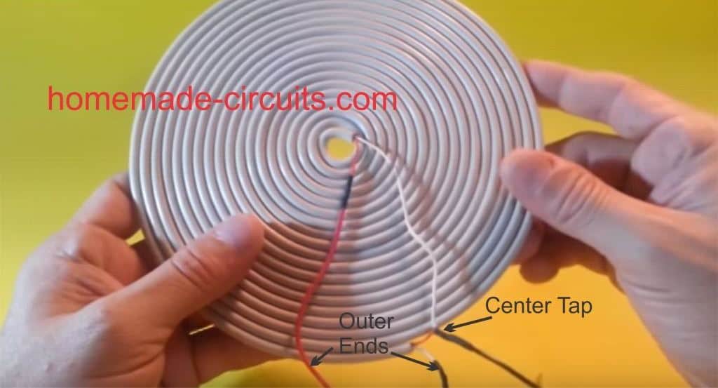
For this you may have to procure an 1800W induction cooktop (for around $55), next, you will need to build a bifilar coil that should be approximately the same size of the induction coil inside cooktop.
The next step would be to configure the bifilar coil in the form of a power source, and connect its end terminals with a power connector module.
After this, plug in or attach the appliance or the load as per your own preference, for optimal response make sure the load is a resistive type appliance for ensuring best efficiency, for example you could try using an incandescent light bulbs, water heaters, soldering iron etc.
In the actual prototype it was found that at around a load of 4kW the lamp started showing signs of fluctuations and dimmed a little so it seemed that it may not be suitable to increase the load above this value, so don't go over that for each induction device.
Testing the Free Energy Output Results
Once the above set up is installed, you are just about ready to watch the power of free magnetic energy at an awesome level.
For this to happen you simply go ahead and plug in the cooktop into your home AC live power socket .....and position your DIY bifilar coil right on top of the induction cooktop and WHAT...you will be surprised to see a massive 4 kWH of power being delivered for an input of just 1.8kW from your home AC.
In few of the modern cooktops you may find a feature where the cooktop does not start until a ferromagnetic vessel is introduced over it....so you may have to do this extra bit just to make sure your induction cooktop starts normally.
In the actual prototype it was noticed that powering at a maximum 4kW load, my homemade bifilar coil on top of the cookware reached a maximum temperature around 46.3°C.
The system should work for 110-120V single phase inputs at above price. You can try it with 208-240V 1P inputs, or 240-600V 3Phase input also, however this might mean that the cost of the stovetop increasing proportionately. Nevertheless this might probably allow you to power your entire house with a 240V, 3500W induction heater cooktop with absolutely no utility bills troubling your bank account.
Try this and let us know how it works for you!!
WARNING: THE EXPERIMENT INVOLVES LETHAL MAINS VOLTAGE THAT CAN KILL ANY LIVING BEING INSTANTLY.
BE EXTREMELY CAREFUL WHILE CONDUCTING IT, AND PREFERABLY DO IT UNDER THE SUPERVISION OF A QUALIFIED TECHNICIAN.


Questions & Answers
Hi Swagatam and thank you for the article? Have you built and tested this or similar circuit ?
Thank you.
Hello, I hope you are doing alright. I am mechanical engineer and about 70 years old. I am interested in electronic subject. would you please help me to build a simple 500 watts induction heater.
best regards
reza
Thank you Stoyan, sorry no, I have not tested this concept practically.
Is it possible /convenient for you to build simpler design for test verification?
Thank you.
Yes, you can build or buy a small scale version of the induction heater as explained in the following article, and check the output response by replicating the induction heater coil for the receiver coil, and use a small resistor load like bulb etc across this coil..
https://www.homemade-circuits.com/simple-induction-heater-circuit-hot/
It’s nice to see the cold electricity you can run things many kw and you can tach with heand but the problem is how to remove the iron plate so the bifilar coil to colect all the pover of manetic induction. If you know how to remove the iron and the induction cooker to work normally.
I agree, the metal cover of the induction heater will need to be removed for an effective transfer of the inductive current, which actually looks difficult.
So how about taking the inducion hot plate apart, and removing the ferrite bars below it, and put a bifilar coil beneath and above the induction coil. Harvest energy from both sides. But dont put the internal electronics beneath the induction coil again. The ferrite bars were shielding the electronics. Build it up differently?
There is no such thing as free energy, if you are
able to achieve this feat you will win the Noble award
and have 100 hit men after you.
The electricity coming out of this bifiler coil may be cold electricity. I saw a video in Spanish (my second language) in Mexico where a fellow got into a pool of water and took the lamps powered from this type of coil powered by an induction heater and placed them under the same water he was standing in. The lamps worked fine under water and he did not get electrocuted as he said that this was cold electricity which was not just a story.
I saw the same exact amazing video. My idea to make it way better is take the hob apart, put a coil on each side, attach a fractal capacitor bank step up , then spark gap to the same FC stepped down . Then if your input is eg solar 2000w with hot E battery input, then can charge over 4000w of rectified cold electricity, into cold only charged ultra cap bank.John Bedini taught us how to go from hot to cold conversion with an invertor. For the input, you could have a parallel system of 500W induction just to convert back to hot e at over 2000w to the hot input battery.
Hi,
Did you perform any power measurements on the current drawn by the cooker in your experiment? Or did you assume that, because the plate on the cooker says 1.8kW, that it actually draws 1.8kW when used in this way?
Since the inductive cooktop is a big coil, intended to use magnetism to induce eddy currents in the cookware. If you replace the cookware with a coil, the cooktop will induce currents in the coil instead. What you have created is a transformer. Power drawn from the secondary of a transformer increases the current drawn by the primary.
The reason the lights are flickering at 4kW, I imagine, is because you are overloading the cooker, which is not designed to deliver double its rated output.
Hi,
Thanks for your valuable feedback. I have not yet tested the concept practically, however what you say makes sense.
Good day to you. Can you please tell me how to bypass the pot detection shutoff for most induction cooktop?
Greetings sir, and thank you for many of your schemes and knowledge. We remember the times when we stretched tens of meters of conductor high above the ground and barely reached some micro or millivolts, which we directed with a Ge diode or a crystal detector and powered the headphones. And today they write on this principle that they will gain a kilo or MW. Perpetuum is probably still undiscovered. So far, the power cannot be greater than the power input. Like that. Best regards.
Thank you for your interesting feedback Marian, appreciate it!
Sir,
Thanks for your quick reply.
If the output passes through a bridge rectifier we will get a DC then if same connected to an inverter with high voltage (600V) in the place of PV connection, would it work properly? And get a pure AC supply!
Or even the Dc can be used to charge the battery of inverter system.
Hi Hassan, yes that looks feasible. If you are able to extract 600V Dc that can be easily used in a full bridge inverter and achieve 220V through a step down transformer.
Sir,
Going through your site its like exploring a forest plenty of nature’s living plants and animals.
About the “free energy from induction cooktop” from my opinion the output should be a high frequency Ac supply at the same voltage input. This high frequency will not affect the apparatus connected to it (load with coils). On the net I have seen that only incandescent load connected (resistive).Please elaborate.
Thanks
Thank you Hasssan, I am glad you liked my website.
I agree with you, high frequency is necessary. Yes only resistive load is preferred, as they esy to implement without technical complications.
FIRST I WOULD LIKE TO THANK YOU SO MUCH FOR YOUR SITE.
I HAVE BUILT MANY OF YOUR CIRCUTS. YOU ARE A GODSEND TO A PERSON LIKE ME.
I HAVE A FREESTANDING RANGE WITH A BAD CONTROL BD. NOT COSTEFECTIVE TO REPAIR
SO I HAVE DECIDED TO USE IT AS A FOOD DEHYDRATOR.
I HAVE REWIRED BOTH UPPER AND LOWER ELEMENTS IN SERIES PUT THEM TO 110 INSTEAD OF 220
I ALSO PUT A 10 AMP DIODE IN SERIES TO CUT OUT HALF THE AC WAVE.
IT NOW DRAWS JUST UNDER 3 AMPS BUT IS STILL A BIT WARM FOR MY PURPORSE
COULD U DESIGN A TEMP. CONTROL CIRCUIT? IS IT POSSABLE TO USE THE OVEN SENSOR?
THANKS IN ADVANCE BRUCE
I am glad you liked my posts, I think you can try one of these circuits to achieve the required temperature control effortlessly:
https://www.homemade-circuits.com/2012/04/how-to-make-simplest-triac-flasher.html
No sensors are required
THANKS SO MUCH SHOULD WORK FINE
Dear sir:
Re: Testing the Free Energy Output Results
On the circuit description says: “…you will be surprised to see a massive 4 kWH of power being delivered for an input of just 1.8kW from your home AC.”
I think you can create more energy at the Output side of a device than the energy that is present at the Input side.
My Pleasure!
Thanks for posting about the Generating Free Energy. Really helpful
Hi everyone!
Please help me.
I have got the cooker top MC-STW2019 (doesn’t metter model).
I am going to make a induction heater for melting a solder.
The problem is to bypass the controller inside which Switch OFF in 2 hours.
How can I manually turn on the heater?
Thank you in advance!
Hi Tom, you will have open the gadget and examine the relay circuit which is responsible for switching OFF the system, and then modify the circuit such that the relay is unable to switch or the stage is disabled…this will enable you to make the system work with interruption
hello, thank you for your post. can you kindly tell me what is the supply voltage of the induction cooktop. how do i design the induction heater power supply to be compatible with the 220v household supply. thank you , waiting for your response
hello, I have comprehensively discussed the details in the following article, you can refer to it for the required info:
https://www.homemade-circuits.com/2016/09/designing-induction-heater-circuit.html
This is fake and should be removed. The article spoils an otherwise excellent site.
I have updated the article with a warning message at the top….
The 24v will come from the battery and then fed to the dc-dc converter which amplifies it to 220v dc which will now be fed to the oscillator circuit or moreover you can type homemade pure sinewave inverter circuit on youtube there you will understant what i'm talking about but if the 24vdc will be converted to 220vac with pure sinewave output (not modified sinewave)i won't mind the main thing there is the pure sinewave circuit diagram
the 220V DC conversion is necessary not for the sinewave conversion but rather when a H-bridge topology is used, for an ordinary center tap transformer you can skip the DC stage and still make pure PWM sine wave….
you can try the last circuit from this article
https://www.homemade-circuits.com/2016/02/pwm-sinewave-5kva-inverter-circuit.html?m=0
Hi sir i need a pure sinewave inverter circuit(not modified) which can be build by using dc-dc converter which will convert 24v to 220vdc which will now be fed to the oscillator pls sir i will be much happier if u'll help me with it cos i saw a guy post the video on youtube
Hi Victory, from where the 24V is supposed to come?
and what's the function of 220V DC and the oscillator??
It would be better if the 24V was directly converted to 220V AC,
Please elaborate?
Hello Victory. Really clear-sinusoidal exit power generator is possible via primary DC-motor with secondary AC-generator rotating machine with a system of r.p.m. stabilization ONLY!!!!!!! Other circuits are generate close to be sinusoidal exit power – with a 1-5% harmonical frequencies typycally. These harmonical frequences is made acustic noice of all motors ans of all transformers with overheat of these=lost of primary power to a heat. No depends – half-bridge or full-bridge or (much more worster) pushpull or feedback or blocking-generator used as a power-converter – the main is how to operate THE jt or the mosfet or the igbt or other THE keys within THE regime gap of the design – it is wery difficoult to obtain less than 0.1% of harmonics.
If you look for 220V 50Hz inverter “for life” – you could open the Mr.Swagatam’s site’s – Arduino – for 1 or 3 phases drivers for your inverter. Power part of your inverter – at another places of the site or else.
If you need maximal economy of you primary-power 12-24V DC – you could select an appropriated lamps and funs and other loads instead of 220V items. Also you could open your TV-Computers-others for an attampt of “to give primary 12-24V DC to the device directly to it’s board” or just cut off insulation of power adapter’s low voltage (5-22V=adapter’s exit) wires for to give primary power of batatry (12-24V DC) to it (via ballast resistors or similar against overvoltage\overcurrent) – a sharp knife with soldering iron with few other parts than to insulate properly – half of a hour of work after calculations. Good luck.
hi sir…..I have an idea…. we use stabilizer for amplifying AC voltage…. can u make a circuit to amplify DC voltage (like 9v to 12v amplifier)…… forgive me if I am talking like a fool….
Hi Soumen, you can use a boost converter circuit or a joule thief kind of circuit for getting the results, it's an old concept and the principle is used in all transformer based circuits where a higher voltage than the source is required.