DRL or Day Time Running Lights are a chain of bright lights mostly LEDs installed just under a vehicle's headlight, which illuminate automatically during day time to ensure that others can distinctly notice the vehicle approaching even from a distance.
The following customized DRL circuit was requested by Mr. Jivesh
Technical Specification as Provided by the User
Respected Sir,
I need your help for a circuit to control a DRL in my car and I searched many websites online for the circuit I wanted for my car.
These are the functions I want the circuit to perform :-
1. Light should Turn on when the Ignition starts
2. Lights should Dim to 50% when I turn on the parking lights/headlights.
3. The lights should blink with the indicators and come back to normal state when indicators turn off With a fade effect.
4. After turning off the car the DRL should turn off after 2 minutes ( Coming Home Feature )
The DRL have only two wires 12 volt Positive and ground only.
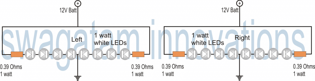
Circuit Diagram
DRL with 1 Watt LEDs
The next circuit of a DRL or a Day Time Running Light was requested by Mr.Senthil. So I have explained the complete design.
Technical Requirements
Hello Sir,
I'm an avid DIYer. Recently, i was looking to make a DRL(daytime running light) for my car using 1 watt smd LEDs.
But i couldn't find an appropriate circuit for my need. I want to drive Eight 1watt LEDs from my car battery.
I would very much appreciate if you could design a simple and rugged circuit to drive 8 x 1watt leds from a 12-14v input.
I'm also planning to add a heat-sink to dissipate any heat generated by the leds.
Thanks & Regards,
Senthil
The Design
What's a DRL or Day Time Running Light Device:
A DRL is a safety car lighting device specifically assigned to moving vehicles for increasing the conspicuity of the vehicle during day time, especially when the daylight is accompanied with fog or during dull overcast days.It is normally fixed just beside the headlamps on either sides.
Normally a DRL system is in the form of constantly illuminated high intensity lamp. With the advent of modern High intensity LEDs, making a DRL lamp is matter of less than an hour.
As per the request the proposed day time running light or DRL circuit would be in the following form:
However in case you are interested to spice up the above idea a bit, and think that the system should do justice to the name that it has been specified, you would want to make it a literally "running" or chasing kinda thing!
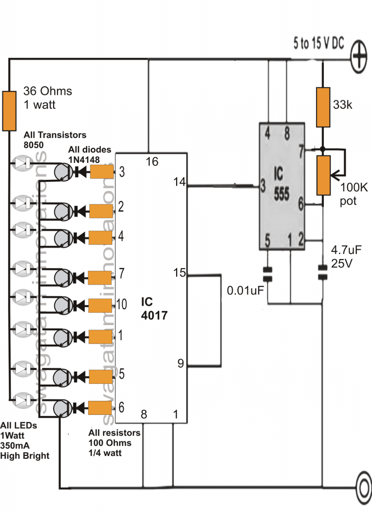
Making a Chasing DRL Circuit
The DRL circuit discussed below shows how we can add a running effect to the above design and make it further interesting.
The circuit is actually a straightforward powerful LED light chaser circuit which is able to drive many 1 watt LeDs in a sequential manner.
The IC 4017 is a Johnsons Decade counter which generates a sequential switching at its 10 outputs in response to positive pulses fed at its pin#14. These pulses are referred to as clock signals.
As can be seen in the given circuit diagram, the IC 555 is configured in its basic astable multivibrator mode, and generates the required clocks for the IC 4017.
The clock pulses are taken from pin#3 of the IC555 and fed to pin#14 of IC4017.
In response to the above clocks, the output of the IC 4017 shifts a high logic sequence from pin#3 to pin#6. The moment it reaches pin#6, the sequence reverts to pin#3 and the cycle repeats.
Since only 8 LEDs are requested, pin#9 is connected to the reset pin of the IC so that the only 8 outputs become active with the required functions.
The speed at which this sequence may "run" or "chase" will depend on the setting of the 100k pot. Any value between 1 to 5 Hz may be set by suitably adjusting the pot.
The transistors respond to the sequencing high pulses at their bases and switch ON the connected 1 watt LEDs in the same pattern creating a powerful dazzling "running" LED light effect.
Since the illumination is very powerful, would become visible even during daytime and on foggy days and thus the circuit becomes very suitable as a DRL unit and may be used in cars as a Day Time Running Light device.
Chasing Dark Spot LED DRL Circuit
For creating a "running dark spot effect" use PNP transistors in place of the NPN ones, connect the emitters to the positive, and connect the LEDs across the collectors and ground. Do not forget to reverse the LED polarity too.
2) Smart Car DRL Controller Circuit
The second design explains how the DRLs in a car may be controlled by reducing its intensity while the headlamps or the indicator lamps are being used, for enhancing its efficiency. The idea was requested by Mr. Rob. I have explained more about this smart DRL intensity manager circuit.
Technical Specifications
Hi Swag,
I'll try and explain in more detail. I want a module which will connect to a set of aftermarket DRLs that will allow them to turn on when the cars ignition is on (ideally via direct battery connection with a voltage sensor to turn them on but if not via ignition live feed).
The module needs to connect to the headlight so that when it is turned on the DRLs dim to 50%.
The module also needs to dim the DRLs when the indicator is activated on that particular side of the car (right DRL dims when right indicator is turned on etc.).
This aspect isn't necessary when the headlights are on as the DRLs are already dim. When the indicators turn off I would like the DRL to fade back to full brightness say over a period of 2 seconds or similar.
It is basically just like the new Audi DRLs which are built into their headlights.
I hope this is enough information for you to produce a schematic but if not I can try and give you some more information. Also, using your relay method would be best!
Thanks
Rob
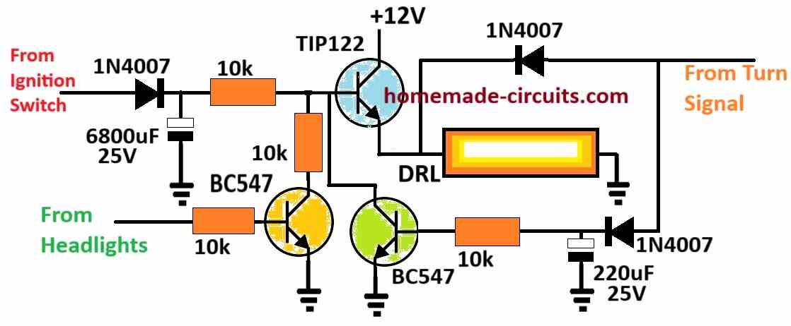
The Circuit Design
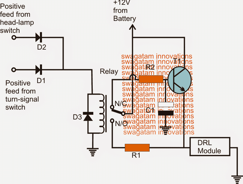
The proposed smart, energy efficient DRL controller circuit could be constructed in any of the following methods.
The first one is a rather crude approach which will provide the intended results but will not save any electricity for you, so the purpose could fail here.
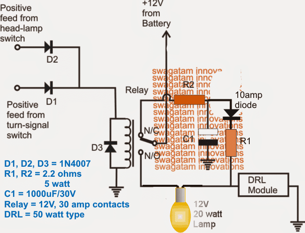
The T1 stage is included for enabling the fade-back effect over the DRL, if this feature is not required, T1, R2, C1 may be entirely eliminated and the N/C of the relay directly joined with the junction of DRL positive and R1.
C1 decides the gradual brightening period of the DRL
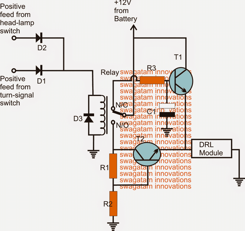
The second design could be considered energy efficient due to the inclusion of a voltage regulator stage incorporating T2, R1, R2. T2 is configured as a common collector.
Here T1 and the associated parts perform the same function as above while T2 is rigged to produce 50% less voltage for the DrL when the headlights or the turn signals are switched ON.
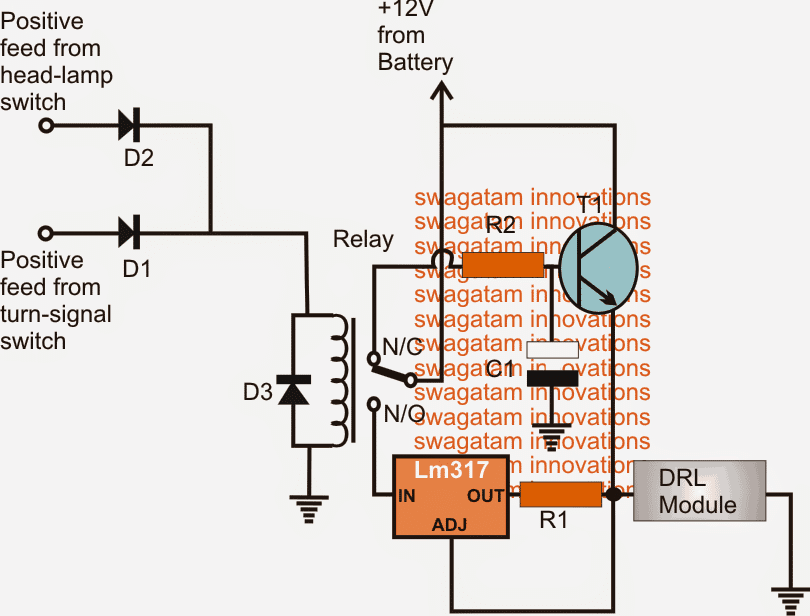
The last circuit is also a smart way of controlling the DRL illumination.
Here the T2 stage has been replaced with the LM317 current regulator stage which controls the DRL intensity by 50% during the recommended situations but unlike the second circuit it executes the operations by reducing the current instead of voltage.
Circuit Diagram
Parts List for the above circuit designs
- R1, R2, R3 = 10k
- T1, T2 = TIP122
- D1, D2 = 1N4007
- D3 = also 1N4007 (optional)
- Relay = 12V, 400 ohms, SPDT
Parts List for the above circuit design
- R1 = 1.25/DRL amp value (less 50%
- R2 = 10k 1/4 watt
- C1 = 470uF/25V
- T1 = TIP122
- D1, D2 = 1N4007
- D3 = also 1N4007 (optional)
- Relay = 12V, 400 ohms, SPDT
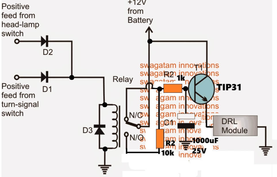
Simplified Dimming Design
For the DRL dimming feature, the extra current current-control stage using a BJT or LM317 is actually not required and can be simply implemented using a high value resistor, as shown in the following diagram.
You will need to optimize the R1, R2 values for getting the correct brightness on the DRL, as required.
Feedback, and suggested corrections from Mr. Rob
Hi Swag,
Thanks for doing the schematic of the DRL Indicator module. The reason we need it to dim is to make it legal in the UK to have DRLs and Indicators so close to each other.Anyway, I've ordered the parts for the schematic as I'm short on a few bits however just a query with the 12v + supply to the battery.
As the battery is constantly live will this 'module' be constantly draining power when the car is not in use as the DRLs would always be on? If it were a 'ignition live' positive feed then this would only provide power to the 'module' when the ignition is turned on.
What are your thoughts on this? Do we need to look at installing another circuit which goes to the battery that has a separate trigger switch that can identify when the car is not being used/ignition off?
Thanks again
Rob
Analyzing the Feedback Query
Hi Rob,
You are right, the +12V needs to come from the ignition feed, meaning only when the ignition is switched ON, the DRL and the associated circuitry should be triggered ON for the required operations.So the modification will be simple, instead of connecting the +12V to the battery we can integrate it with the ignition 12V feed.
The above smart DRL circuits could be also used for high watt DRL applications, an example 50 watt modification is illustrated below:
The 12V, 20 watt series lamp could be hidden somewhere under the bonnet, it's included for dipping the DRL illumination to approximately 50% less.
Upgrading DRL to a Solid State Version
The above designs can be upgraded to solid state versions by completely eliminating the relay, and repalcing it with an inexpensive BJT stage as shown below, the idea was requested by Mr. Dhar Vader
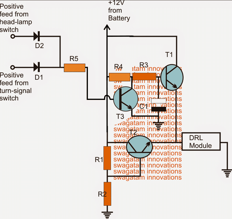
Parts List for the above Solid State Automatic DRL circuit:
- R1, R2, R3 = 1K, 1watt.
- R4, R5 = 10k, 1/4 watt
- T1, T2 = TIP122
- T3 = BC547,
- C1 = 470uF/25V
- D1, D2 = 1N5408
3) Multi-Feature DRL Circuit
The 3rd idea below discusses a multipurpose high power DRL circuit which can be used as park lights, head lights and also to specially respond to turn signal lights in order to light up the kerbs while passing through unpredictable blind turns or corners and subways.
The idea was requested by Mr. Ian Auxley.
Circuit Objectives and Requirements
- I have just found your web site and I am very impressed with your wonderful knowledge and friendliness.
- I am very interested in Automotive projects. I have designed and built a circuit using old tech stuff like auto relays, diodes, and resistors etc, all soldered together in a wooden box.
- This circuit works perfectly. It is used to turn on fog lights as day time running Lights and is also used to turn each one independently when either turn indicator is flashing on, the light uses capacitors to hold the relays on and not flash, it draws power from the indicators I this mode.
- In drl mode it draws power from the battery, there are 2 micro switches on the indicator stalk, one is a momentary to flash the drls and the other is to turn the drls on or off at night when the headlights are on.
- Some upscale cars use them when turning right or left to light up the kerbs and driveways when the indicators are used. I would like to make this into a solid state circuit that is smaller and easier to fit.
- I would like to have a circuit drawn up as a hobby project so anybody could use it.
- The lights I used in the older car I had were just dichroic 12v 60w household down lights with 60deg angle, I would love to use high powered LED lights instead.
- I could send you a hand drawn copy of the circuit if you are interested as used but not sure of values for diodes and resistors.
- I have other project ideas as well if you are interested.
- Could you help with the design.
Designing a Multipurpose Power DRL Circuit for your Car
Referring to the request above, the idea could be summarized in the following manner:
1) two powerful LED lights to be used on the left/right sides of the car, which can be used as DRLs, park lights as well as head lights.
2) These lights needs to be controlled through separate switches as fog light, park light, and DRL lights.
3) The DRL light circuit should include the feature which ensures that when a side indicator is ON (flashing), the opposite DRL LED should be switched ON, but the DRL on the flashing indicator side should be switched OFF, however once the turn light is OFF the DRLs must return to their normal condition.
The above feature needs to be implemented regardless of whether the DRLs are originally switched ON or not.
4) The unit needs to be solid-state in nature, and should avoid mechanical operators such as relays.
Circuit Diagram
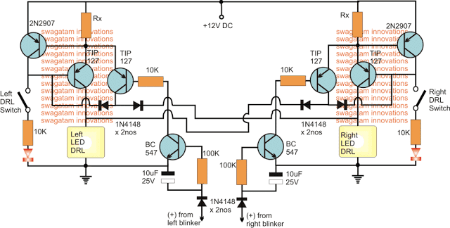
The image above shows the intended solid state version of a high power DRL circuit with the recommended features, the details may be understood with the help of the following points:
1) two exactly identical stages can be seen on the left and the right sides, which form the respective DRL stages, along with a couple of delay timer stages for the specified switching actions through the turn signal feeds.
2) the 2N2907 and the associated TIP127 transistors form a simple current controlled LED driver stage for controlling the high power LED DRLs safely.
3) The other TIP127 transistor along with the BC547 forms a delay OFF timer stage intended for converting the flashing feed from the turn signal lights into a relatively constant DC.
4) The TIP127 delay OFF timers on L/R sections are configured in a such manner that it switches OFF it switches ON the opposite DRL while keeping its relevant side DRL ON.....
For example suppose while the left side indicator is active, the right DRL is forced to switch ON regardless of whether it's originally switched ON or not, and at the same time it forces the DRL at its own side to switch OFF regardless whether it's originally switched ON or not.
Exactly similar conditions are implemented for the right side indicator switching also.
The switches shown at the extreme sides allow the user to switch the DRLs ON or OFF together or individually at will.
The two LEDs confirm the powering of the DRLs and vice versa.


Comments
Mr. Swagatam,
Thank you for you post. I’m a mechanical engineering and I don’t know much about electronics.
However, I have problem in my DRL controller (NCC/ML-017PWM). I opened the controller and I found one of IC burn (IC3). I couldn’t get out the part number from it. In this DRL circuit three ICs ; IC1(12F629), IC2 (AS358M), and IC3 (burn). Does it possible to figure out that IC and its function.
Thanks.
Hi Hamad, Those seem to be microcontroller and op amp ICs, and it can be almost impossible to judge their complex configuration. Only the manufacturer could be having the exact details and the codes of the design
Hello, I am glad to be here. I am requesting for a circuit for my car. I need a circuit which will show up in the dashboard in the form of a blinking LED whenever any of my brake lights are faulty, or not working
Hi, you can use the last circuit from the following article:
https://www.homemade-circuits.com/car-fused-brake-light-bulb-indicator/
The LED can be replaced with a blinking LED module.
Hello Sir, Could you kindly design me a headlight controller circuit diagram for my motorcycle? I want to have the headlight (of 60/55W halogen) ON automatically when the alternator starts generating power (13.8V which is normal floating voltage for LA battery) and switches it OFF after 10~15secs of shutting down the engine. I am really appreciating your great work. Thanking you in advance.
Hi Anjan, I think you can try the first diagram from this link:
https://www.homemade-circuits.com/interesting-timer-circuits-using-ic-555-explored/#Timers_for_car_lights
Good day Mr. Swagatam.I like your website very much and the ideas that you posted and all the help you give all the people.I am very impressed. I am interested in a circuit that make gunshots sounds and if you keep the button pressed it changes to machine gun sounds to be used as my cars hooter.I drive a lot at night and there is animals walking on the road or next to the road.It is a safety hazard .Hopefully they will run away.Thanks.
Pete
Thanks Pete, I have a couple of related circuits posted in this website, you can take a look at them. However combining them together could make the design a bit complex, so I would suggest to use any of these for your application, since any one of these will be enough to fulfill the mentioned task.
https://www.homemade-circuits.com/loud-pistol-sound-simulator-circuit/
https://www.homemade-circuits.com/make-simple-machine-gun-sound-effect/
Hello Swagatam,
Many thanks for this wonderful resource.
I have two very cheap ‘COB’ (chip on board) LED lights that I’d like to use as daytime running lights, however they are just the LED units themselves each with a +ve and -ve wire only. I’d like to connect them so that they switch on when the engine starts and switch off when the engine stops, but also have a on/off switch if I decide to switch them off while the engine is running.
My question is, would you kindly advise what other components (relays, resistors etc) I should use to maintain a steady current so the LEDs won’t flicker or dim/brighten when the alternator is charging the battery? If you could provide a diagram as well that would be greatly appreciated.
The specs are as follows:
Input voltage: 12V
Input current: <1A
Power output: 10W (each unit)
Best regards,
Jay
Thank you Jay,
you can apply the 3rd last circuit from the following article:
https://www.homemade-circuits.com/universal-high-watt-led-current-limiter/
to stabilize the LED illumination, you will have to feed the 12V supply to the circuit through a 6A4 diode, and connect a 2200uF/25V capacitor right across the LED terminals. The diode ensures that the charge on the 2200uF cap does not escape to other loads rather works only for the LEDs.
Please make sure to calculate the parts values as per the given formulas
Good Morning Sr
May I have a circuit for DRL using turn lights? the amber lights for turn signal?, like tacoma or Dart, they use turn light as a DRL, Thanks in advance.
Hello, please explain more regarding the operational details of the both lamps, so that I can understand the two specifications separately
the function is actually when the car is turn on, the front amber lights turn on , then if turn left or right side that amber light turn off and on like normally works after turn car and go straight that amber light stop blinking then turn on and stay on until a turn function aplies again. Thanks
I think the last diagram from this article might help solve your query:
https://www.homemade-circuits.com/illuminating-drl-and-turn-lights-with/
hi,
i want make DRL circuit for car , 9w/12v lead, 5 LEDs each side. please help me with circuit diagram.
hi, connect the 5 LEDs in parallel with each LED having a series 2 ohm 1 watt resistor…connect the ends of this parallel connection with the battery through the DRL switch.
Hi,
I could not correctly understand your need, do you need a LED controller circuit which would allow you to dim the DRLs or switch them OFF??
Hello Sir! Thanks for all your contribution to the common knowledge of mankind! You provided great ideas/examples! I came to your site in search for a voltage-stabilized circuit so that the LEDs are neither overdriven nor underutilized, when operated from the cars 12-14V. Do you have something in your mind/archive? 🙂 Thanks a lot!
All the best to you Balogh! and keep your fingers crossed ;D
Thank you! Now I got the final push to go buy some stuff and start playing around! 🙂 Thanks again! Time to blow some parts up, the kids are gonna enjoy this! Gotta buy some protective glasses, too, I guess… 😀
Thanks Balogh, you can try the following two concepts for safeguarding the LEDs optimally:
https://www.homemade-circuits.com/2013/06/universal-high-watt-led-current-limiter.html
https://www.homemade-circuits.com/2011/12/make-hundred-watt-led-floodlight.html
Dear sir.
I got it right now. Thank you very clearly explained to me
you are welcome rajkumar
Dear sir
Please help me In first circuit i have used smd5730 led type 3.2 to 3.4 volt 0.5watt 150mAhIt. Exactly how much will unite resistor
Dear Rajkumar,
assuming the input to be 14V and the number of LED = 4, the value of the resistor will be
14 – (3.3 x 4) / 0.15 = 5.33 ohms
wattage = 0.8 x 0.15 = 0.12….so a 1/4 watt will do.
Can you give me a reliable automatic water control with auto shutdown water pump and automatic street light controller circuit from your web site? Used for home purpose
Thank you sir
Satheesh, please search it using the search box, you will be able to find a good range to choose from
Respected sir,
In first circuit Can i used to 8mm? instead of 1 watt, led
8mm led specification Color: White
8 " mm "Straw Hat 0.75 watt
yes satheesh, you can use 8mm LEDs in the first circuit
use 75 ohms for the resistors
Dear Sir,what if I would drive 100 Incandescent lights to make a running light?
Will the Chip 4017,have another version that has Many Outputs up to 100…
Or I will just have to reconfigure the pins to make it perform up 100?
Should I just use a relay to power the incandescent from the mains?
Thank You Very Much Sir!
Dear Jordan, The IC 4017 has only one version with 10 outputs..so you may have to put the lamps in parallel for implementing 100 bulbs
you will need to use triacs for operating the bulbs as shown in the second circuit below:
https://www.homemade-circuits.com/2013/06/knight-rider-led-chaser-circuit-mains.html
but this circuit is designed to produce a to-and-fro or a reverse forward kind of chasing effect
Thanks. I did my maths too. Came to same conclusion.
One additional note: what do I need to do if the signal that I have is a PWM signal instead of 12v on/off. Can I use this with the same schematic? I can add another wire from the battery 12v but would like to use this drl signal which will originate from the board control module.
Thanks again.
If the PWM current is adequately rated then it may be directly fed to the DRL lamps via the switch, if the PWM input is weak, then you might need a transistor driver in the middle.
you can do it using a TIP127 transistor…connect its collector to the DRL, emitter to the 12V positive through the DRL switch….and the base can be connected with the PWM input via a 10k resistor.
HI I have a similar design as the first schematic but only 6 LEDs per site (Left/Richt). However my leds are 1 Watt high power LED (3,4-3,6 Vf and 300-350mA If). I would like to use the 10,8 – 13,8V battery from my car and use these as my DRL.
What kind of schematic would I need to create?
Thanks for your help.
you can make two strings of 3 LEDs each…with a 8 ohm 1 watt resistor with each string…then you can put these two strings in parallel on each channel
make sure the LEDs are mounted on heatsinks
hi sir, in the first circuit, how did you come up with the value of the resistor ie 0.39ohms 1w.regards
hi matheka, I used the following formula:
R = (Us – LEDv)/LED amp
Us = 13.5V or 14v
LEDv = 3.3 x 4 = 13.2
LED amp = 0.3
sir, you can also provide a second circuit using 0.5watt leds.
yes you can use 0.5 watt leds also
Hi sir,
I would like to build a brake lamp project using 1 watt high power leds, consisting of 12-15 leds.
the leds would light on dim praking lights and would light full on brake pedal press. kindly provide me a circuit..
kind regards,
Awan
Hi Awan,
Please check it out, I have posted the design here:
https://www.homemade-circuits.com/2015/04/led-brake-light-circuit.html
Hi Mr. Swagatam, Can i please have the circuit design.
regards, Awan
thanks, appreciate your patience, will do it soon.
sure, i will be waiting for the circuit design, thanks
Hi Awan, I'll try to post it soon, keep in touch until then
thank you in advance
kind regards,'
Awan
Hi Swagatam.
I would like to build circuit with HID 2x35W and DRL led 2×8 (each 1W). HID running at dark and LED diodes at day, could be ambient light sensitive.
The lights will work just with key in ignition (keysense +6V).
Thanks
Vlad, here's the design:
https://www.homemade-circuits.com/2014/04/ambient-light-sensitive-relay-circuit.html
You will have to do the following steps:
Take a 12V relay, connect its coil one end to negative supply.
Connect its other terminal to the headlamp switch positive output, so that now whenever head light is switched ON, the relay also activates closing its N/O contacts.
Now just simply you have wire the above relays N/C contact and pole, with the DRL and the tail lamp such that the DRL and the taillight lamps get their ground or negative suppies via the N/C contacts.
It means only as long as the above relay is in a non-activated mode, the DRL and the taillight would get access to the negative supply for switching ON, the moment the relay is activated the DRL and the taillights would be cut off from the negative ;line and will no longer be able to illuminate.
Dear sir I have accurate current controlled circuit which is used in audi,BMW, benz for long life of LED's. I used this circuit since 2 years as a my bike headlights and DRL in my car. Same lighting since 2 years. I copy it from audi drl. It's work 3 led s in series and can run any of need. Just need some resistors, transistor, mosfet with heat sink
Ok great!
try this one:
https://www.homemade-circuits.com/2013/10/make-this-diwali-christmas-running.html
Hi Swagtam Sir
Im a hobbyist. Looking for a driver circuit for 8 x 0.5W SMD LED for DRL.
Can you please suggest me which value of resistor I use?
Thanks in advance
Waiting for ur reply sir.
Ajay Sehgal
Hi Ajay,
You can try the second circuit from the following link, you will need to calculate the resistors correctly as per the given formulas
https://www.homemade-circuits.com/2013/06/universal-high-watt-led-current-limiter.html
I am looking for a circuit to dim some LED Day Time Running lights, whilst the indicator is flashing. ie Full brighness when indicator is OFF(not flashing) and 50% brightness but on constant while indicator is flashing. like with Audis.
ie
No Indicator(not flashing) = LED DRL on full brightness
Indicator flashing = DRL LED on 50% brightness. DRL LED's must not flash.
If headlight is on DRL LED on 50% brightness. DRL LED's must not flash.
DRL = Day Time Running Lights.
Can you assist?
Rob, I have published it here:
https://www.homemade-circuits.com/2014/04/smart-car-drl-controller-circuit.html
Will do…looking forward to it!
Hi Rob,
That'll do, I'll try to design it soon and post it for you, please do keep in touch for the update.
Thanks!
Hi Swags,
I'll try and explain in more detail. I want a module which will connect to a set of aftermarket DRLs that will allow them to turn on when the cars ignition is on (ideally via direct battery connection with a voltage sensor to turn them on but if not via ignition live feed). The module needs to connect to the headlight so that when it is turned on the DRLs dim to 50%. The module also needs to dim the DRLs when the indicator is activated on that particular side of the car (right DRL dims when right indicator is turned on etc.). This aspect isn't necessary when the headlights are on as the DRLs are already dim. When the indicators turn off I would like the DRL to fade back to full brightness say over a period of 2 seconds or similar.
It is basically just like the new Audi DRLs which are built into their headlights.
I hope this is enough information for you to produce a schematic but if not I can try and give you some more information. Also, using your relay method would be best!
Thanks
Rob
Hi Rob, surely I can do it.
Would you mind sending a brief write-up explaining the above functions elaborately as per your understanding. The longer the better;)
It would help me to add a content with the schematic.
Hi Swags, do you have a schematic you can produce for this?
you can do it in this way:
Use a relay with a 470uF/25V cap connected parallel to its coil.
Connect resistors at it N/O and N/C.
Make the free ends of the resistors common and connect with the respective DRL positive string.
Connect the pole of the relay with supply(+).
Connect the coil terminal which has (+) of the 470u with two 1N4007 diodes cathodes (cathodes made common).
Connect the free diode anodes, one with the flasher output (+) and the other with the headlight (+).
connect the other coil/cap end and the DRL negative to ground.
Select the resistors such that, position N/C produces 100% glow while N/O produces 50% of that.