• Skip to main content
  • Skip to primary sidebar

Homemade Circuit Projects

Get free circuit help 24/7

Circuits for Beginners | Basic Circuits | LED Driver | Hobby Circuits | Transistor Circuits

New-Projects | Privacy Policy | About us | Contact | Disclaimer | Copyright

Home » Mini Projects » Simple Car Shock Alarm Circuit

Simple Car Shock Alarm Circuit

Last Updated on March 17, 2021 by Swagatam 6 Comments

A simple car shock alarm circuit presented in this article can eb effectively used to alarm the owner each time the car comes across some kind of vibrational intrusion ether from a potential theft of simply a damaging hit from  an external source.

Introduction

Today most of the cars are equipped with this type of security feature where an alarm is raised in an event of a shock or a hit made over the car body. The article explains a very simple and cheap car shock alarm circuit which costs hardly 1/2 a dollar yet performs the actions reasonably accurately.

The working Principle of the Shock alarm

The principle employed here is pretty basic, a mic is used to sense the impact, the sensed output is amplified by a transistorized amplifier.

How the Circuits Works

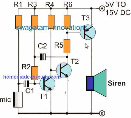
Looking the circuit diagram, the whole functioning can be understood with the following points:

The mic stage consists of the mic itself, the biasing 2k7 resistor and the 47uF coupling capacitor.

T1 and T2 form the first amplifier stage and is the heart of the circuit.

The feedback 100K resistor plays an important function of keeping the amplification sustained at a stable rate.

When a shock impact is sensed by the mic, it converts the shock vibrations into tiny electrical pulses.

T1 and T2 work like a preamplifier, and amplifies the MIC response into a reasonably high electrical pulse, sufficient for driving the power output stage transistor T3 saturation.

The T3 responds to the above signal and activates the connected alarm siren, alerting the folks around regarding the possible theft attempt.

One big drawback of this cheap car shock alarm circuit is that it cannot distinguish between physical shocks and shock waves developed due to loud bangs or noises.

Parts List

  • R1 = 5k6
  • R2 = 47k
  • R3 = 3M3
  • R4 = 33K
  • R5 = 330 OHMS
  • R6 = 2K2
  • C1 = 0.33uF/400V
  • C2 = 4.7uF/25V
  • T1, T2 = BC547
  • T3 = TIP127
  • D1 = 1N4007
  • Siren = Any 12 V car siren

Pendulum Type Shock Alarm

The circuit may be implemented to safeguard automobiles, big items, houses and other sites since the sensor enables you to detect any kind of motion. This gadget may also be used for many technological tests.

The relay can easily power high wattage audio or alarm devices, for example sirens, horns, lights, etc. Standby current consumption is extremely low (around 100 uA) during the time the relay is in the deactivated state, which increases the battery-life.

The schematic diagram of the Pendulum shock Alarm is shown in Figure below.

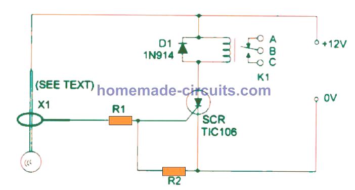
The circuit is centered around an SCR (Silicon Controlled Rectifier), that powers ON the relay whenever the sensor picks up any kind of movement. Relay coil voltage is determined based on the power supply voltage. You may use a small DPDT 1A Mini Relay or, for hefty loads, a 10A mini SPDT relay. These types of rlays are usually rated at 12 VDC and consume not more than 38 mA.

Once initiated, the circuit will be latched permanently, in order to reset the circuit, or stop the alarm can be made a small push to ON switch may be wired between the SCR anode and cathode. The leads of the polarized component like the SCR and diode, should be carefully noted and assembled with correct polarity.

Parts List

SCR -TlC106 or SCR
D1 - 1N914 or 1N4148
K1 - 12V relay (see text)
S1 - SPST toggle switch
Rl - 22k, 114W,5% resistor
R2 - 10k, 114W,5% resistor
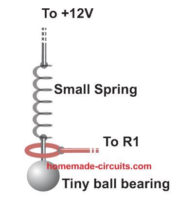
X1 - Pendulum sensor

Pendulum Shock Sensor Assembly

The pendulum sensor is a simple homemade mechanism built using a small ball pen spring, a small steel ball as the load, from any ball-bearing system, and connecting copper wires as shown in the following figure.

Make sure to use a spring that is very delicate and stats swinging even with slightest of jerk or shock.

You'll also like:

  • 1.  LED Tail Ring Light Circuit for your Car
  • 2.  Simple Kitchen Timer Circuit – Egg Timer
  • 3.  Make this Simple Refrigerator Door Open Alarm Circuit
  • 4.  Cyclist’s Safety Light Circuit – Nighttime Visibility for Cyclists, Walkers, Joggers
  • 5.  Simple MOSFET Tester and Sorter Circuit
  • 6.  How to Make HHO Fuel Cell Circuit in Automobiles for better Fuel Efficiency

About Swagatam

I am an electronic engineer (dipIETE ), hobbyist, inventor, schematic/PCB designer, manufacturer. I am also the founder of the website: https://www.homemade-circuits.com/, where I love sharing my innovative circuit ideas and tutorials.
If you have any circuit related query, you may interact through comments, I'll be most happy to help!

Subscribe2


Reader Interactions

Comments

    Your Comments are too Valuable! But please see that they are related to the above article, and are not off-topic! Cancel reply

    Your email address will not be published. Required fields are marked *

  1. Swagatam says

    you will have to use a buzzer coil as shown in the following image:

    img.tradeindia.com/fp/1/728/405.jpg

    Reply
  2. ABRAHAM VIC says

    mr SWAGATAM CAN I GET SOME WRITE-UPS FOR A LIGHT ACTIVATED ALARM,WANNA INCLUDE IT INTO MY PROJECT WRITE-UP.

    Reply
  3. Isidro garcia says

    Dear Swagatam, the inductor is 100uH not 100uf. Saludos y bendiciones desde México

    Reply
    • Swagatam says

      Thank you Isidro, I have corrected the mistake…Please keep up the good work

      Reply
  4. from schaeybroeck mario says

    Dear , I am looking for an automatic light control for the car with LDR , switching off a little delayed , to prevent the light from switching on and off when you drive under trees , for example . Made with a NE555, greetings Mario

    Reply
    • Swagatam says

      I think you can simply implement the delay, by adding a 220uF/25V capacitor across the base emitter of the relay driver transistor which is responsible for switching the car lamp ON/OFF

      Reply

Primary Sidebar

Categories

  • 3-Phase Power (15)
  • 324 IC Circuits (19)
  • 4017 IC Circuits (53)
  • 4060 IC Circuits (25)
  • 555 IC Circuits (98)
  • 741 IC Circuits (19)
  • Amplifiers (58)
  • Arduino Engineering Projects (82)
  • Audio Projects (94)
  • Battery Chargers (82)
  • Car and Motorcycle (94)
  • Datasheets (46)
  • Decorative Lighting (Diwali, Christmas) (33)
  • DIY LED Projects (89)
  • Electronic Components (97)
  • Electronic Devices and Circuit Theory (35)
  • Electronics Tutorial (109)
  • Fish Aquarium (5)
  • Free Energy (35)
  • Fun Projects (11)
  • GSM Projects (9)
  • Health Related (18)
  • Heater Controllers (28)
  • Home Electrical Circuits (101)
  • How to Articles (20)
  • Incubator Related (6)
  • Industrial Electronics (28)
  • Infrared (IR) (40)
  • Inverter Circuits (98)
  • Laser Projects (12)
  • LM317/LM338 (21)
  • LM3915 IC (25)
  • Meters and Testers (63)
  • Mini Projects (171)
  • Motor Controller (66)
  • MPPT (7)
  • Oscillator Circuits (24)
  • PIR (Passive Infrared) (8)
  • Power Electronics (33)
  • Power Supply Circuits (74)
  • Radio Circuits (9)
  • Remote Control (47)
  • Security and Alarm (61)
  • Sensors and Detectors (116)
  • SG3525 IC (5)
  • Simple Circuits (74)
  • SMPS (29)
  • Solar Controllers (61)
  • Timer and Delay Relay (54)
  • TL494 IC (5)
  • Transformerless Power Supply (8)
  • Transmitter Circuits (40)
  • Ultrasonic Projects (14)
  • Water Level Controller (45)

Circuit Calculators

  • AWG to Millimeter Converter
  • Battery Back up Time Calculator
  • Capacitance Reactance Calculator
  • IC 555 Astable Calculator
  • IC 555 Monostable Calculator
  • Inductance Calculator
  • LC Resonance Calculator
  • LM317, LM338, LM396 Calculator
  • Ohm’s Law Calculator
  • Phase Angle Phase Shift Calculator
  • Power Factor (PF) Calculator
  • Reactance Calculator
  • Small Signal Transistor(BJT) and Diode Quick Datasheet
  • Transistor Astable Calculator
  • Transistor base Resistor Calculator
  • Voltage Divider Calculator
  • Wire Current Calculator
  • Zener Diode Calculator

Facebook
Twitter
YouTube
Instagram
My Facebook-Page
Quora

© 2022 · Swagatam Innovations

We use cookies on our website to give you the best experience.
Cookie settingsAccept All
Privacy & Cookies Policy

Privacy Overview

This website uses cookies to improve your experience while you navigate through the website. Please visit the Privacy Policy Page for more info.
Necessary
Always Enabled
Necessary cookies are absolutely essential for the website to function properly. This category only includes cookies that ensures basic functionalities and security features of the website. These cookies do not store any personal information.
Non-necessary
Any cookies that may not be particularly necessary for the website to function and is used specifically to collect user personal data via analytics, ads, other embedded contents are termed as non-necessary cookies. It is mandatory to procure user consent prior to running these cookies on your website.
SAVE & ACCEPT