The following article presents a circuit design which would mute your car amplifier music the moment it detects a cellphone call inside the car, enabling an automatic muting during the situations, and saving the user from the manual hassles.
A loud music could be a nuisance while a phone call is being attended or dialed. We all normally love listening to loud music while traveling in cars, but this could mean problems in case a phone call is required to be attended.
Automatic Car Amplifier Muting
An automatic muting system which could detect a cellphone call and mute the car amplifier automatically for the time being could be quite handy as it would save the user from some frustration, and manual hardwork.
I have explained how this may be possible using the following explained little circuit.
We know that all cellphones generate a significant amount of radio frequency (RF) each time these are activated through an incoming or an outgoing call.
The level of the generated RF could be different for different cellphones but nevertheless some degree of these will be always present around called cellphones no matter how much it's been restricted.
These emitted RFs from a cell phone makes it very easy to sense it's operational condition and could be effectively used for any relevant toggling function through an attached circuitry.
The RF Sniffer
The following circuit shows a simple RF sniffer or detector circuit which could be incorporated for the proposed vehicle amplifier muting while a call is being received or dialed over a cellphone inside the intended premise.
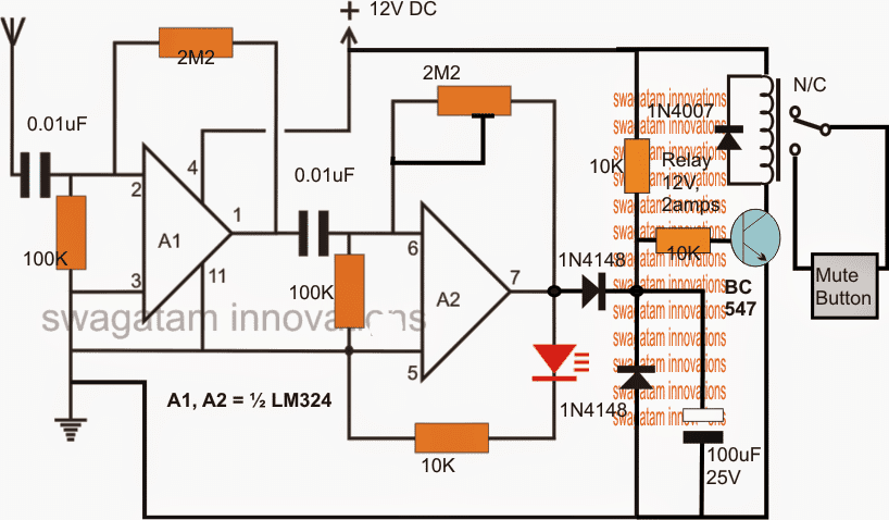
Referring to the figure below, the design basically consists of two stages, the RF sensor made up of by A1 and A2 and a relay driver stage comprising the subsequent BC547 driver stage.
A1 and A2 are each configured as a high gain amplifier and are connected in series for achieving maximum sensitivity.
The feed back resistor 2M2 is responsible for determining the gain or the sensitivity level of the opamps. Increasing it increase the sensitivity and vice versa.
The opamps together become ideally suited for picking up all kinds of RF signals that might be present in the vicinity.
Adjusting the Sensitivity
It's sensitivity could be set by adjusting the 2M2 pot or preset as per the available RF level around.
Inside a car there could be a host of other disturbances other than the cell phone Rf, therefore the sensitivity needs to be tweaked optimally such that the sensor picks up only the RFs from the cell phone and not from the ignition system of the vehicle.
Additionally, more than one of these units could be positioned on differing corners of the car interior and the outputs integrated with the main relay driver so that the receiver is able to detect the Rfs from everywhere inside, and from the cell phones of the members who may occupying the rear car seats.
This will also allow to keep the individual muting circuits set with minimum sensitivity making sure that these units sense only the cell phone RFs and no other spurious disturbances.
Coming back to the proposed car amplifier mute circuit, as soon as a cellphone is activated with a call, the RFs are instantly detected by the circuit's antenna and converted into an amplified DC fluctuating at the cell phones varying emission levels.
The amplified output across A2 outputs is appropriately filtered by the associated diode and capacitor network, and used for driving the relay stage wherein the relay clicks and switches ON the mute terminals of the car amplifier, forcing the music to shut down for the time being, until the call is finished or completed by the user.
Circuit Diagram


Questions & Answers
If its a possibility then what sort of wireless communication can be used ?
433 MHz RF modules could be used to send the signal and trigger a relay
Is there a way in which the muting could be done wirelessly after the cellphone RF is detected
that would make the circuit hugely complex.