DRL or Day Time Running Lights are a chain of bright lights mostly LEDs installed just under a vehicle's headlight, which illuminate automatically during day time to ensure that others can distinctly notice the vehicle approaching even from a distance.
The following customized DRL circuit was requested by Mr. Jivesh
Technical Specification as Provided by the User
Respected Sir,
I need your help for a circuit to control a DRL in my car and I searched many websites online for the circuit I wanted for my car.
These are the functions I want the circuit to perform :-
1. Light should Turn on when the Ignition starts
2. Lights should Dim to 50% when I turn on the parking lights/headlights.
3. The lights should blink with the indicators and come back to normal state when indicators turn off With a fade effect.
4. After turning off the car the DRL should turn off after 2 minutes ( Coming Home Feature )
The DRL have only two wires 12 volt Positive and ground only.
Circuit Diagram
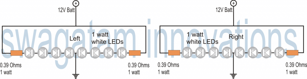
DRL with 1 Watt LEDs
The next circuit of a DRL or a Day Time Running Light was requested by Mr.Senthil. So I have explained the complete design.
Technical Requirements
Hello Sir,
I'm an avid DIYer. Recently, i was looking to make a DRL(daytime running light) for my car using 1 watt smd LEDs.
But i couldn't find an appropriate circuit for my need. I want to drive Eight 1watt LEDs from my car battery.
I would very much appreciate if you could design a simple and rugged circuit to drive 8 x 1watt leds from a 12-14v input.
I'm also planning to add a heat-sink to dissipate any heat generated by the leds.
Thanks & Regards,
Senthil
The Design
What's a DRL or Day Time Running Light Device:
A DRL is a safety car lighting device specifically assigned to moving vehicles for increasing the conspicuity of the vehicle during day time, especially when the daylight is accompanied with fog or during dull overcast days.It is normally fixed just beside the headlamps on either sides.
Normally a DRL system is in the form of constantly illuminated high intensity lamp. With the advent of modern High intensity LEDs, making a DRL lamp is matter of less than an hour.
As per the request the proposed day time running light or DRL circuit would be in the following form:
However in case you are interested to spice up the above idea a bit, and think that the system should do justice to the name that it has been specified, you would want to make it a literally "running" or chasing kinda thing!
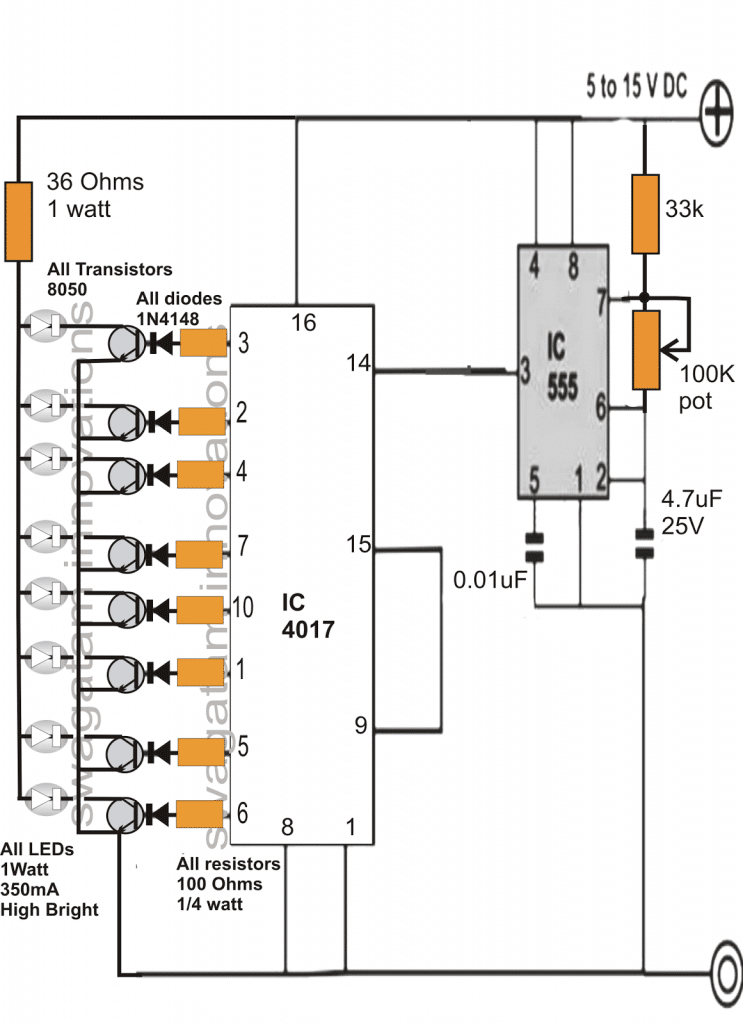
Making a Chasing DRL Circuit
The DRL circuit discussed below shows how we can add a running effect to the above design and make it further interesting.
The circuit is actually a straightforward powerful LED light chaser circuit which is able to drive many 1 watt LeDs in a sequential manner.
The IC 4017 is a Johnsons Decade counter which generates a sequential switching at its 10 outputs in response to positive pulses fed at its pin#14. These pulses are referred to as clock signals.
As can be seen in the given circuit diagram, the IC 555 is configured in its basic astable multivibrator mode, and generates the required clocks for the IC 4017.
The clock pulses are taken from pin#3 of the IC555 and fed to pin#14 of IC4017.
In response to the above clocks, the output of the IC 4017 shifts a high logic sequence from pin#3 to pin#6. The moment it reaches pin#6, the sequence reverts to pin#3 and the cycle repeats.
Since only 8 LEDs are requested, pin#9 is connected to the reset pin of the IC so that the only 8 outputs become active with the required functions.
The speed at which this sequence may "run" or "chase" will depend on the setting of the 100k pot. Any value between 1 to 5 Hz may be set by suitably adjusting the pot.
The transistors respond to the sequencing high pulses at their bases and switch ON the connected 1 watt LEDs in the same pattern creating a powerful dazzling "running" LED light effect.
Since the illumination is very powerful, would become visible even during daytime and on foggy days and thus the circuit becomes very suitable as a DRL unit and may be used in cars as a Day Time Running Light device.
Chasing Dark Spot LED DRL Circuit
For creating a "running dark spot effect" use PNP transistors in place of the NPN ones, connect the emitters to the positive, and connect the LEDs across the collectors and ground. Do not forget to reverse the LED polarity too.
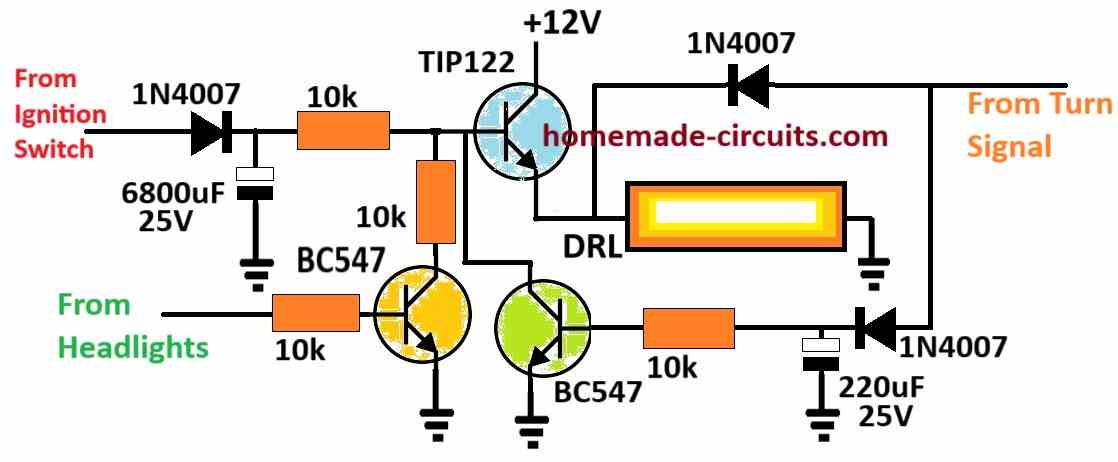
2) Smart Car DRL Controller Circuit
The second design explains how the DRLs in a car may be controlled by reducing its intensity while the headlamps or the indicator lamps are being used, for enhancing its efficiency. The idea was requested by Mr. Rob. I have explained more about this smart DRL intensity manager circuit.
Technical Specifications
Hi Swag,
I'll try and explain in more detail. I want a module which will connect to a set of aftermarket DRLs that will allow them to turn on when the cars ignition is on (ideally via direct battery connection with a voltage sensor to turn them on but if not via ignition live feed).
The module needs to connect to the headlight so that when it is turned on the DRLs dim to 50%.
The module also needs to dim the DRLs when the indicator is activated on that particular side of the car (right DRL dims when right indicator is turned on etc.).
This aspect isn't necessary when the headlights are on as the DRLs are already dim. When the indicators turn off I would like the DRL to fade back to full brightness say over a period of 2 seconds or similar.
It is basically just like the new Audi DRLs which are built into their headlights.
I hope this is enough information for you to produce a schematic but if not I can try and give you some more information. Also, using your relay method would be best!
Thanks
Rob
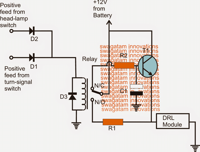
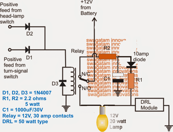
The Circuit Design
The proposed smart, energy efficient DRL controller circuit could be constructed in any of the following methods.
The first one is a rather crude approach which will provide the intended results but will not save any electricity for you, so the purpose could fail here.
The T1 stage is included for enabling the fade-back effect over the DRL, if this feature is not required, T1, R2, C1 may be entirely eliminated and the N/C of the relay directly joined with the junction of DRL positive and R1.
C1 decides the gradual brightening period of the DRL
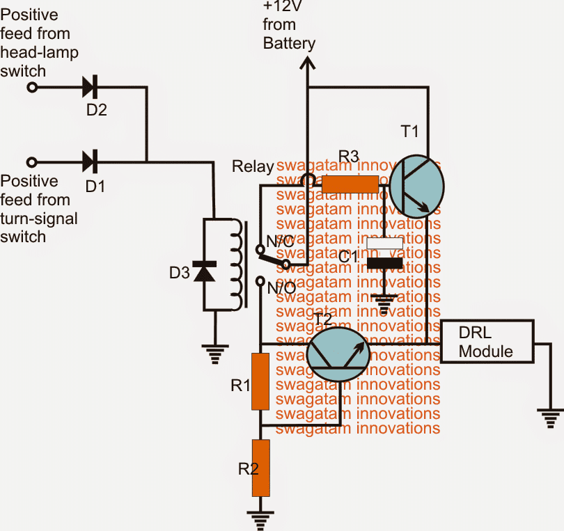
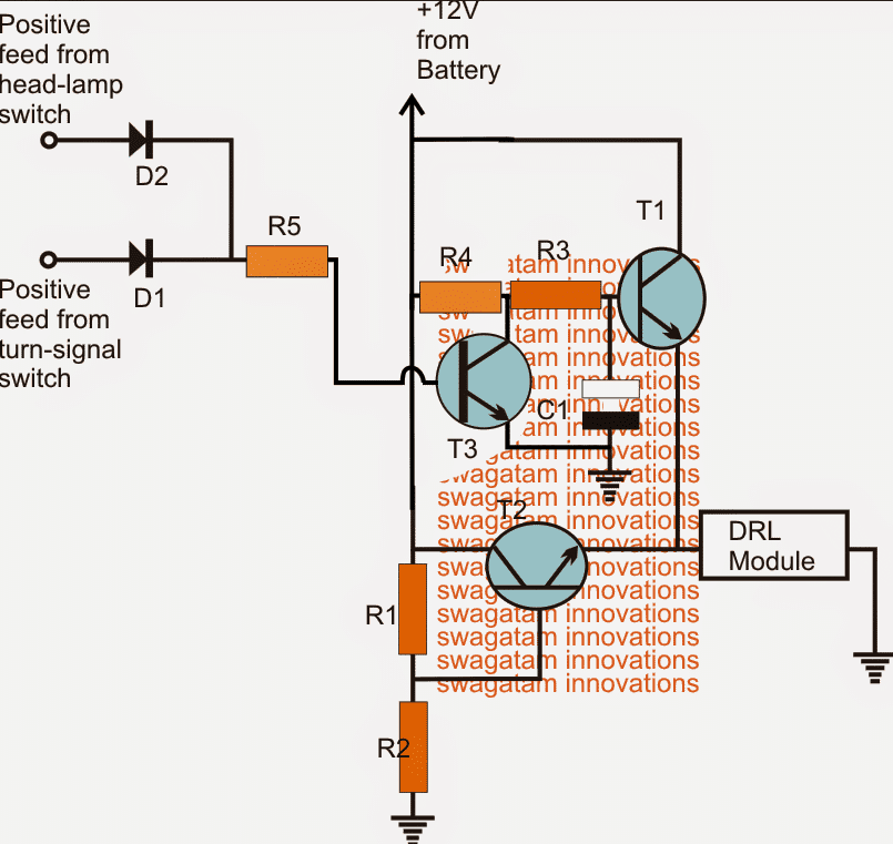
The second design could be considered energy efficient due to the inclusion of a voltage regulator stage incorporating T2, R1, R2. T2 is configured as a common collector.
Here T1 and the associated parts perform the same function as above while T2 is rigged to produce 50% less voltage for the DrL when the headlights or the turn signals are switched ON.
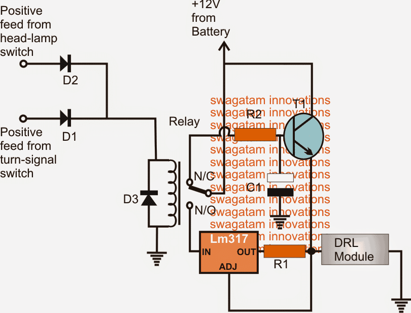
The last circuit is also a smart way of controlling the DRL illumination.
Here the T2 stage has been replaced with the LM317 current regulator stage which controls the DRL intensity by 50% during the recommended situations but unlike the second circuit it executes the operations by reducing the current instead of voltage.
Circuit Diagram
Parts List for the above circuit designs
- R1, R2, R3 = 10k
- T1, T2 = TIP122
- D1, D2 = 1N4007
- D3 = also 1N4007 (optional)
- Relay = 12V, 400 ohms, SPDT
Parts List for the above circuit design
- R1 = 1.25/DRL amp value (less 50%
- R2 = 10k 1/4 watt
- C1 = 470uF/25V
- T1 = TIP122
- D1, D2 = 1N4007
- D3 = also 1N4007 (optional)
- Relay = 12V, 400 ohms, SPDT
Simplified Dimming Design
For the DRL dimming feature, the extra current current-control stage using a BJT or LM317 is actually not required and can be simply implemented using a high value resistor, as shown in the following diagram.
You will need to optimize the R1, R2 values for getting the correct brightness on the DRL, as required.
Feedback, and suggested corrections from Mr. Rob
Hi Swag,
Thanks for doing the schematic of the DRL Indicator module. The reason we need it to dim is to make it legal in the UK to have DRLs and Indicators so close to each other.Anyway, I've ordered the parts for the schematic as I'm short on a few bits however just a query with the 12v + supply to the battery.
As the battery is constantly live will this 'module' be constantly draining power when the car is not in use as the DRLs would always be on? If it were a 'ignition live' positive feed then this would only provide power to the 'module' when the ignition is turned on.
What are your thoughts on this? Do we need to look at installing another circuit which goes to the battery that has a separate trigger switch that can identify when the car is not being used/ignition off?
Thanks again
Rob
Analyzing the Feedback Query
Hi Rob,
You are right, the +12V needs to come from the ignition feed, meaning only when the ignition is switched ON, the DRL and the associated circuitry should be triggered ON for the required operations.So the modification will be simple, instead of connecting the +12V to the battery we can integrate it with the ignition 12V feed.
The above smart DRL circuits could be also used for high watt DRL applications, an example 50 watt modification is illustrated below:
The 12V, 20 watt series lamp could be hidden somewhere under the bonnet, it's included for dipping the DRL illumination to approximately 50% less.
Upgrading DRL to a Solid State Version
The above designs can be upgraded to solid state versions by completely eliminating the relay, and repalcing it with an inexpensive BJT stage as shown below, the idea was requested by Mr. Dhar Vader
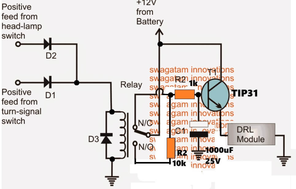
Parts List for the above Solid State Automatic DRL circuit:
- R1, R2, R3 = 1K, 1watt.
- R4, R5 = 10k, 1/4 watt
- T1, T2 = TIP122
- T3 = BC547,
- C1 = 470uF/25V
- D1, D2 = 1N5408
3) Multi-Feature DRL Circuit
The 3rd idea below discusses a multipurpose high power DRL circuit which can be used as park lights, head lights and also to specially respond to turn signal lights in order to light up the kerbs while passing through unpredictable blind turns or corners and subways.
The idea was requested by Mr. Ian Auxley.
Circuit Objectives and Requirements
- I have just found your web site and I am very impressed with your wonderful knowledge and friendliness.
- I am very interested in Automotive projects. I have designed and built a circuit using old tech stuff like auto relays, diodes, and resistors etc, all soldered together in a wooden box.
- This circuit works perfectly. It is used to turn on fog lights as day time running Lights and is also used to turn each one independently when either turn indicator is flashing on, the light uses capacitors to hold the relays on and not flash, it draws power from the indicators I this mode.
- In drl mode it draws power from the battery, there are 2 micro switches on the indicator stalk, one is a momentary to flash the drls and the other is to turn the drls on or off at night when the headlights are on.
- Some upscale cars use them when turning right or left to light up the kerbs and driveways when the indicators are used. I would like to make this into a solid state circuit that is smaller and easier to fit.
- I would like to have a circuit drawn up as a hobby project so anybody could use it.
- The lights I used in the older car I had were just dichroic 12v 60w household down lights with 60deg angle, I would love to use high powered LED lights instead.
- I could send you a hand drawn copy of the circuit if you are interested as used but not sure of values for diodes and resistors.
- I have other project ideas as well if you are interested.
- Could you help with the design.
Designing a Multipurpose Power DRL Circuit for your Car
Referring to the request above, the idea could be summarized in the following manner:
1) two powerful LED lights to be used on the left/right sides of the car, which can be used as DRLs, park lights as well as head lights.
2) These lights needs to be controlled through separate switches as fog light, park light, and DRL lights.
3) The DRL light circuit should include the feature which ensures that when a side indicator is ON (flashing), the opposite DRL LED should be switched ON, but the DRL on the flashing indicator side should be switched OFF, however once the turn light is OFF the DRLs must return to their normal condition.
The above feature needs to be implemented regardless of whether the DRLs are originally switched ON or not.
4) The unit needs to be solid-state in nature, and should avoid mechanical operators such as relays.
Circuit Diagram
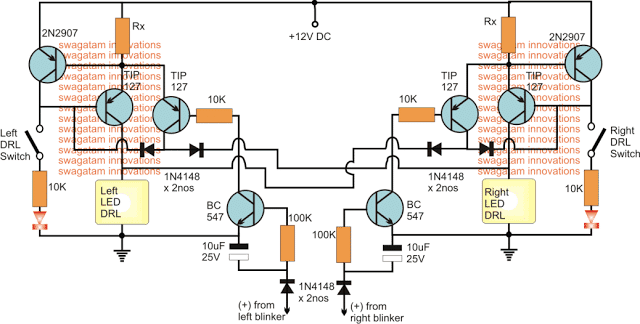
The image above shows the intended solid state version of a high power DRL circuit with the recommended features, the details may be understood with the help of the following points:
1) two exactly identical stages can be seen on the left and the right sides, which form the respective DRL stages, along with a couple of delay timer stages for the specified switching actions through the turn signal feeds.
2) the 2N2907 and the associated TIP127 transistors form a simple current controlled LED driver stage for controlling the high power LED DRLs safely.
3) The other TIP127 transistor along with the BC547 forms a delay OFF timer stage intended for converting the flashing feed from the turn signal lights into a relatively constant DC.
4) The TIP127 delay OFF timers on L/R sections are configured in a such manner that it switches OFF it switches ON the opposite DRL while keeping its relevant side DRL ON.....
For example suppose while the left side indicator is active, the right DRL is forced to switch ON regardless of whether it's originally switched ON or not, and at the same time it forces the DRL at its own side to switch OFF regardless whether it's originally switched ON or not.
Exactly similar conditions are implemented for the right side indicator switching also.
The switches shown at the extreme sides allow the user to switch the DRLs ON or OFF together or individually at will.
The two LEDs confirm the powering of the DRLs and vice versa.


Questions & Answers
Hello Swagatam,, i’ve found your blog very helpfull for me to knowing about circuit and how to apply DRL..
Now, i’ve an idea: how we can make the DRL only light up when the engine is running, and DRL shut down when engine is stop.. i’ve ask to AI before, but when i try, its can’t fix this problem.. i’m sure you can help me about this.. thanks a lot Swagatam..
Hi DavyOg, It is actually very easy.
In the first circuit diagram, just replace the “from ignition switch” with “from alternator 12V AC”
As far as I can see in the circuit, if the Daytime Running Lamp LEDs are power LEDs and connected in series, it makes 9.9 V. If we calculate the 10k voltage divider resistors, it will be 6V at the Base of T2 and 5.4V at the Emitter. The LEDs will not light up, but if each LED is connected in parallel to 12V with a resistor, this time the LEDs will emit less light, I think this should be what is wanted from the circuit. There is only one problem, if the collector of T1 and the common contact of the relay are directly connected to 12V, this time the DRL lights will remain on continuously in the relay position NO or NC. In my opinion, the main power supply of the circuit should be taken from the ignition switch output, not directly from the 12V battery.
Thank you for your insightful analysis! You are correct regarding the voltage calculations and DRL operation in series versus parallel arrangements. Also your point concerning the relay connection and continuous functioning is correct, taking the main power from the ignition switch will resolve this issue. We appreciate your helpful opinion!
Where can i find a DRL controller that fits UK standards? Any help would be great
Sorry, I have no idea about it. If you can tell me the specifications, I can perhaps design the circuit for you….
Sorry, im restoring a 2005 Vauxhall Astra but it has no DRLs so i was looking to install Sequential DRLs with a module that will either dim the DRLs or turn them off when the main beam comes on. I should add im using 3w dual White/Amber power leds. Thanks
You can try making the following design. The values of R1 and R2 resistors will depend on the number of LEDs used:
Thank you so much will give that a try, i appreciate it
DRL LIGHTS UP WITH THE HEADLIGHTS AND ALL OTHER DESIGNED FUNCTIONS EXCEPT WHEN IT IS DAYTIME, THE DRL ARE NOT WORKING OR VERY DIM UNTILL IT IS IMPOSSIBLE TO SEE IF THEY ARE ACTUALLY ON. I BELIEVE THEY ARE NOT ON AT ALL.
Multipurpose Power DRL Circuit for your Car
Thank you for your design, I have a few questions about the circuit.
This circuit will work for the upgrade I wish to perform on my truck, however I want the DRL’s to operate when the headlights are off and turn off when the headlights come on with all other functions of the circuit intact.
Could I substitute a set of dry contacts from a relay to provide the ground to the 2N2907’s? Would the 10k resistors still be needed or are they simplify there for the voltage drop on the LED’s?
What are the values of Rx? Is this a value that needs to be calculated?
Do the 2N2907’s need heat sinks?
One last question, could this circuit be built then potted?
Thank you in advance.
Yes that’s possible. I think the current limiter with RX stage can be removed, and instead separate current limiters could be added with the individual LDR modules. These current limiters could be built using LM338 IC
According to me the following design should work for you. If you are having a separate free relay contacts available from the headlight relay, you can replace it with the existing DRL ON/OFF switches. Yes the 10K and the LED would be still required
Hello sir, i need a circuit diagram for car DRL which turn on when we unlock the car as well as with the ignition of car. If you can help its i will be thankfull .
Hello Anoop, for that you just have to connect the DRL positive line with the unlock switch or the ignition switch.
Hello there,
I found this website not long ago, and i amazed your work.
I’m searching a DRL solution for my car, but i have no luck so far, maybe you can help me. I have an aftermarket headlight which has a built-in led parking/position light which i would like to use as my DRL with dimming function when the dipped beams are on and it will be nice if my taillight also be on when the DRL is on (without the dimming of course ). I would like to use my headlight switch to power the parking lights ( the two sides separately ) on full power when the ignition is off. And the timer function in DRL mode will be nice to have too.
Thanks for you help.
Hi, thanks for your query, and glad you liked my website!
I will try to figure out an appropriate circuit for your requirement.
Could you please tell me the wattage of the parking light LED? This is important since the transistors will have to be rated according to the rating of the LED, and a current controller will also need to be designed in accordance with the wattage of the LED.
Hi, thanks for your reply. The front leds are 1W/headlight ( at least that’s was written on the housing). The rear ones are 5W halogen bulbs now, but later i would like change them to led. Thanks again.
I have tried to design a simple one, as given below:
Rx can be calculated using the formula, assuming the supply from the witch is 12 V:
Rx = 0.7 / LED current
= 0.7 / 1
= 0.7 Ohms / 1 watt
Ry determines the dimming level on the LED when car headlight dipper is ON….Ry will need to be tested by some trial and error until the right dimming is achieved.
the 10k preset determines the optimum brightness on the DRL in normal conditions.
=
….the DRL LED is supposed to be rated at 12 V, lower values can make the TIP122 hotter….
thank you. I ordered the parts and i will make try to make the circuit. I will keep you updated.
No problem, hope it works for you!
Hi I have found some really nice & bright DRL’s I want to fit to my 2004 A209 Mercedes CLK Convertible. I have purchased this kit:
It is nice and bright and has a resistor built into the circuit as you will see. On my CLK the single filament BAU 15S (single filament) bulb holder completes the circuit when installed into the headlamp unit. The bulb holder itself has no wiring loom attached to it. The circuit is only completed when locked in position into the headlamp unit. The kit advises to insert the LED bulb in place of the bulb holder, insert the bayonet cap into the bulb holder, screw resistor unit to metal, and provide 12V power. But the cabling prevents the bulb holder from being inserted into the headlamp body and thus you cannot complete the mechanical/electrical circuit because the wires trail out of the headlamp unit from the LED bulb. Which means the circuit isn’t complete and does’nt work. Is there anyway of getting around this problem ? Appreciate any help or advice ?
Hi, the wiring loom and the resistor is simply not required, the holder itself must accommodate the current control circuitry, so that the unit can be easily plugged into an existing socket. It should be as discussed in the following article:
https://www.homemade-circuits.com/making-led-halogen-lamp-for-motorbike/
Hello from Canada and Thank You for your generous contributions!
I came upon this website using Yandex as a search engine as Google never came up with useful suggestions (I wish Yandex was incorporated in my browser but that’s another matter).
I’ve been looking and looking for ways to make so-called “DRL Compatible” LED Headlight Bulbs actually run correctly in DRL (Daytime Running Light) mode, which means, RUNNING THE LIGHTS AT REDUCED INTENSITY, because it seems that the only solution LED Headlight manufacturers offer, is to run the lights at FULL INTENSITY, which is both dangerous (blinding) and defeats headlight flashing as a signaling device.
Can you think of an add-on circuit that would essentially detect the DRL mode reduced voltage (in this mode the headlights are connected in series and see half normal voltage of 12-14V), that would take the full voltage that these LED kits feed in this mode and chop it up in high frequency pulses to reduce intensity to the proper level, in a similar manner to the way it’s done in cheap LED flashlights?
Thank you in advance for considering this much needed design!
Thank you for visiting, and appreciate you feedback!
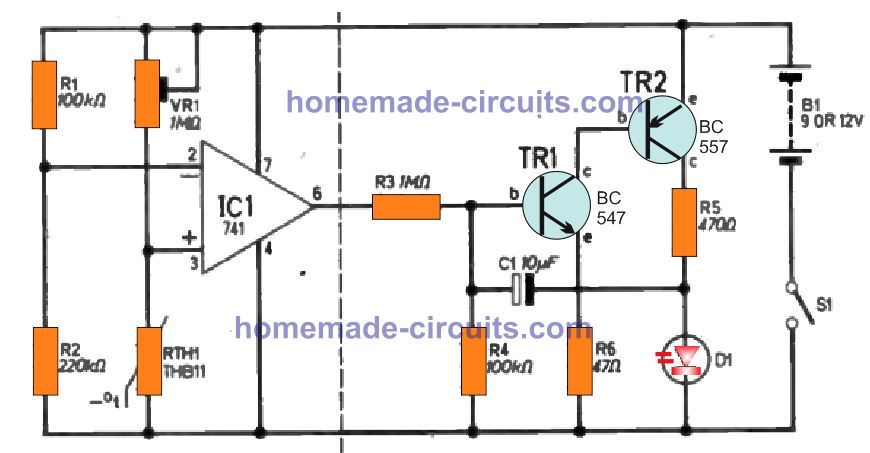
You can easily do it using the following 555 pwm concept and with the mentioned modifications
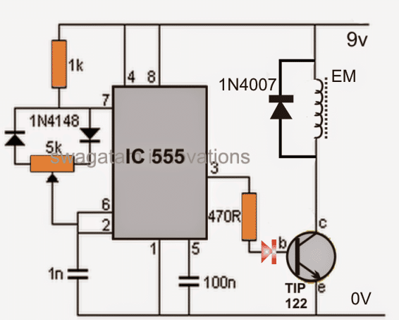
1) Replace the TIP122 with TIP127, which is a PNP transistor
2) Connect its emitter directly to the positive supply, and connect the DRL across its collector and the supply ground line
Let me know if you have more queries regarding the same….
…the red LED polarity must be reversed for the PNP
Hello, thank you for you information and this blog.
could you make a circuit for 6 leds 5W 780mA, this is for one side of the car, and the oder side its the same!
when i turn on the left blinker, the DRL left have to turn off, as well as the other side. but when i turn off the blinker the DRL turn on after 2 or 3 seconds. and could you put a potmeter can be used to adjust the brightness of DRL. please and
I am sorry for my english, i hope you will undertand me.
thank you.
I am from colombia.
Hello, you can try the following modified design
adjust the value of the capacitor for the 2/3 second delay.
The right side transistor is TiP122
Thank you Swagatam, I did it in my protoboard, and its working well, but the TIP122 started so hot in a few seconds that the plastic on the protoboard started to melt, so what can i do? and the C1 I put 330 mF 25v Its ok?, or which can i put?
thank you.
Glad it is working Sebastian, the TIP122 will get hotter as the pot is rotated to dim the LED, and will be less hot at the maximum LED brightness.
You will need a large heatsink to control the heat of the transistor.
If you wan the transistor to be cooler and without a heatsink, then you may have to employ a PWM based design such as this:
Please ignore the 470R print near the IC pin3
Thank you Swagatam, I really appreciate it.
thats works great. ita perfect!¡
i am sorry for a lot questions.
I have another one, I want to when i turn off the blinker the DRL turn on after 2 or 3 seconds, how can i do that in this diagram?
thank you.
You are welcome Sebastian, the 100uF provided at pin5 was supposed to delay the switch ON of the DRL, if it is not helping, you can try putting another 100uF across the anodes of the two diodes and the ground line. I am sure this will provide the required delay for the DRL switch ON whenever the turn signal switch or the headlight switch is turned OFF.
….you can put the DRL at the emitter side of the transistor also, if common ground becomes necessary for the DRL installation.
Thank you Swagatam, I have a question, the DRL MODULUE means the led? and the second where can i put a potmeter that can be used to adjust the brightness of DRL. thank you for you answer, i really appreciate.
You are welcome Sabastian, yes it is supposed to be your 6 led 5W 780mA LED module, please make sure to have an appropriate current controller in the module.
The pot is given in the diagram, just below the DRL module.
Hi Swagatam…
First of all i have to apologize its gonna be a long question but since i searched for so long and this site looks like its the only one where i can get help i think ill give it a try.
I saw loads of circuits for drl with sequential turn signals(loads of them really) but its so confusing. So what im trying is to find a circuit that have 8 output channels for 8 leds(high power white/yellow leds 3.2v 300mA 1w).So for example drl is ON and when you turn ON the turn signal it switch back to yellow flow style and when you turn OFF the turn signal drl is back ON. I dont know very much about techical stuff but i can say that i know enough that if i see it i can make it. So in short 8 dual color leds 3.2v 300mA 1w with switcback function from one to another(using some relay maybe).
Sorry if my english is hard to read, maybe thats why i cant find what im looking for
Hi Adnan, you can use the second circuit for creating a flowing effect. You can use any standard relay for toggling between this circuit and a continuous DRL lamp. The coil of the relay will be powered from the supply coming from the turn signal relay.
The relay pole will go to the positive battery supply, N/O will go to the positive line of the 4017/555 circuit, so that when the turn signal is powered, the battery positive activates the 4017/555 LED circuit and turns ON the 8 sequential running LEDs.
The N/C of the relay will connect with the other 8 LEDs for a fixed illumination, so that when the turn signal is not operating, these setof LEDs remain ON permanently ON.
The coil of the LED must be connected with a 470uF/25V capacitor in parallel so that the relay does not oscillate with the turn signal ON/OFF rather stays ON solid as long as the turn signal is flashing
First thank you for fast reply.
Second circuit is actually what i tought that is the best option for this. So by adding relay for a switcback that should be it and now my only question left is about overheating because it is for a high power leds. I will use small 1_3w led drivers for each yellow led and one larger 7_9w driver for white diodes. That should keep optimal power for all leds and i asume your circuit can be used as a long time solution because as i saw you are expert in this.
You can replace the shown transistors with TIP122 if the LEDs are high watt type, that will ensure proper working of the circuit
I actually made it easy but i was wondering is this circuit design like this. When power is on first led turn on then off and after that second led on and off and so on. Is there i way to make it that first led turn on then second one without first to go off and so on?
Also its like prevoius circuit… For use with high power leds of 1watt
For 1 watt LEDs you can use C106 SCR on heatsink, and calculate the series resistor appropriately through the following formula:
R = (supply V – LED V) / LED Current
Is it possible to use some replacement for scr bt169 because i tryed and its kinda impossible to find it in my country
It is possible by using the concept explained in the following article:
https://www.homemade-circuits.com/sequential-bar-graph-turn-light/
Hi Swags
The problem: Replacing OEM Headlamp assembly with aftermarket headlamp assembly. The DRL system in the target vehicle functions by operating the highbeam headlamps at approximately half illumination whenever the engine is operating in daylight. It does this by doing the following:
“The BCM monitors inputs from the parking brake switch and the combination switch (lighting and turn
signal switch) to determine when to activate the daytime light system. The BCM sends a daytime
light request to the IPDM E/R via the CAN communication lines. The IPDM E/R grounds the daytime
light relay 1 which in turn, provides power to the ground side of the LH high beam lamp. Power
flows backward through the LH high beam lamp to the IPDM E/R, through the high beam fuses, through
the RH high beam lamp circuit to the RH high beam lamp and on to ground. The high beam lamps are
wired in series which causes them to illuminate at a reduced intensity. When daytime light relay 2 is open, it
prevents headlamp low beam from turning on while daytime lights are operating.”
With that in mind, each aftermarket headlamp assembly comes with a bi-xenon headlight with hi-low beam and an additional halo led which I want to use as the DRL’s, instead of the bi-xenon hi beams. The scenario would be this:
When DRL circuit is activated, the Halo led’s are turned on instead of the high beam of the bi-xenon headlight.
When DRL circuit is off, the Halo led’s turn off and the bi-xenon hi/low beam are turned on, depending on driver selection at stalk.
I was considering a voltage sensing relay connected at each headlight assembly wired to detect the reduced voltage coming through the ground wire and then relay 12VDC or battery power to the halo led’s. When power removed from ground then halos go out allowing normal operation of the bi-xenon hi/low beam. Is this possible?
Can you help me out.
NorthernHawk
Hi NorthernHawk,
Designing the circuit as per your above instructions can be difficult for me. I may try designing it, if you can explain the terms in the following sequence:
1) The specifications of the individual lamps.
2) How the lamps are wired and their function.
3) How these lamps need to operate with respect to the various manual switching.
4) What are the automatic changeover sequences these lamps must go through in response to the manual switching.
Thanks Swagatam for these awesome ideas
I have an idea that depends on your 2nd DRL circuit (Chase DRL)
There are 2 color bi led , what I want is a dynamic turn signal ( I am achieving it via a PIC 16f628a IC) with turn indicator and chase DRL both in same circuit so the idea is when the DRL First turns on it do the chase dance as it should and when the turn indicator is on it shuts off completely and back on with fade effect after 2-3 sec delay again after dynamic turn signal is off .
Another thing is the Circuit is based for 8 LEDs what if I have more LEDs. There are mr16 drivers that provide constant current also can drive 2-3 (or even more power LEDs with another type of drivers) but how to wire them is series
And the last thing I want DRL and Position light with same lights the bi color led in that white lights for both(Without out any dimming option it can be achieved via my car Central electronics) and yellow as turn indicator with dynamic turn indication
Please guide me with this
Thank you Sudhanshu, do you want the chasing effect to happen only once, when the car ignition is started? And how should the DRL operate after this initial chasing effect, and when the turn signals are not operational? The 8 LED can be increased up to 10 through one IC, and up to 18 by using two 4017 ICs.
Thanks for the reply
Yes, The DRL chase should happen only at initial ignition start . Afterwards when the Turn indicator is on if should be completely off and when the indicator shut off DRL should come back on with fade effect(like illuminating from 0% brightness then stepping up all the way to 100%).
Is it possible to use 3 led in pair , the negative voltage should be supplied from 4017 IC to npn transistor to the negative supply of mr16 driver which supply the power to 3 led. In such way we can get 8×3 Led only using one 4017 IC
OK, but since I don’t know the specifications of MR16 it will be difficult for me to design it with these LEDs, I can only modify the second circuit above using standard LEDs such as 1 watt LEDs or any other similar