• Skip to main content
  • Skip to primary sidebar

Homemade Circuit Projects

Need circuit help? Post them in the comments! I've answered over 50,000!

Blog | Categories | About | Contact | Calculators-online
You are here: Home / Automobile Electronics / Darkness Activated Car Head Lamp Circuit with DRL

Circuit Simulator: Assemble and Simulate

Darkness Activated Car Head Lamp Circuit with DRL

Last Updated on November 27, 2023 by Swagatam Leave a Comment

In this post I have explained a simple automatic darkness activated switch for car head lamps and the DRLs, initiated by the ignition triggers. The circuit helps to save battery power and prevents unnecessary wastage of energy. The idea was requested by Mr. Vladnemir.

Table of Contents
  • Technical Specifications
  • Designing the Circuit
  • Circuit Diagram

Technical Specifications

I would like to build switch for driving car lights.
I want to use HID pair (2x35W) and DRL 2x8(LED 1W per diode)
Everything must be sensitive on ambient light and working just with key in the ignition (key sense +6V).

Thank you 

Designing the Circuit

The requested design of a ignition triggered and darkness activated dual head lamp circuit can be easily made using the ubiquitous IC 555.

As shown in the figure below, the entire circuit consists of two exactly identical stages comprises of two IC 555 configured as comparators.

The LDRs are used for sensing ambient light conditions and their deteriorating intensities.

R1 on both the circuits are adjusted such that the respective ICs attain a particular light detection thresholds depending upon the user preference.

For example the left R1 may be adjusted such that the relay just triggers when sun just begins to set, while the right hand side R1 may be set such that its relay gets activated only when its completely dark.

As long as the above levels do not reach, pin2 of the ICs are allowed to receive a ground potential which keeps the corresponding pin3s at high, thereby inhibiting the relay activations.

As soon as the respective thresholds are crossed, pin2 goes high via R1, consequently pin3 becomes low allowing the relay to get activated and illuminate the relevant lamps as suggested by the requester.

Pin4 which is the reset input of the ICs are integrated to the ignition positive of the vehicle so that the circuit responds with the above actions only when the car or the vehicle is being used and not while its parked or not in use.

Circuit Diagram

warning message: electricity is dangerous, proceed with caution
Darkness Activated Car Head Lamp Circuit with DRL

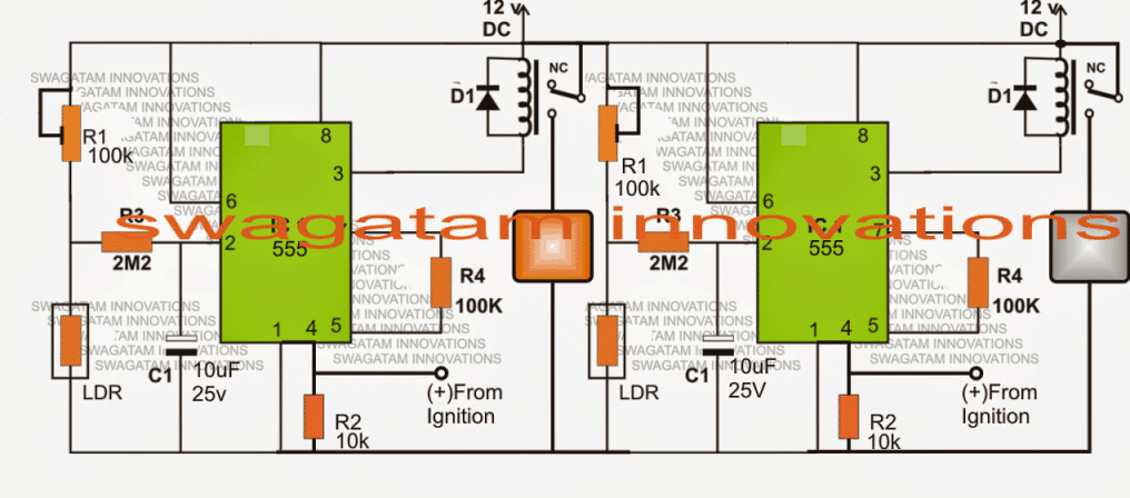
The above diagram indicates how the proposed darkness activated car head lamp and DRL circuit can be built using a couple IC 555 stages

You'll also like:

  • 1.  Car Warning Tone Generator for Ignition, Headlight, Turn Lights
  • 2.  Accurate Speedometer Circuit
  • 3.  Car Radiator Hot Indicator Circuit
  • 4.  GSM Car Ignition and Central Lock Circuit Using Arduino
  • 5.  Automotive Sensor Substitute Circuit Diagram
  • 6.  Understanding Motorcycle Voltage Regulator Wiring

Filed Under: Automobile Electronics Tagged With: Activated, Darkness, DRL, Head, Lamp

About Swagatam

I am an electronics engineer and doing practical hands-on work from more than 15 years now. Building real circuits, testing them and also making PCB layouts by myself. I really love doing all these things like inventing something new, designing electronics and also helping other people like hobby guys who want to make their own cool circuits at home.

And that is the main reason why I started this website homemade-circuits.com, to share different types of circuit ideas..

If you are having any kind of doubt or question related to circuits then just write down your question in the comment box below, I am like always checking, so I guarantee I will reply you for sure!

Previous Post: « Float Switch Controlled Water Level Controller Circuit
Next Post: 4 Automatic Staircase Lamp Controller Circuits Explained »

Reader Interactions

Need Help? Please Leave a Comment! We value your input—Kindly keep it relevant to the above topic! Cancel reply

Your email address will not be published. Required fields are marked *

Primary Sidebar


Subscribe to New Posts

Categories

  • Arduino Projects (89)
  • Audio and Amplifier Projects (132)
  • Automation Projects (17)
  • Automobile Electronics (101)
  • Battery Charger Circuits (83)
  • Datasheets and Components (104)
  • Electronics Theory (143)
  • Free Energy (37)
  • Games and Sports Projects (11)
  • Grid and 3-Phase (19)
  • Health related Projects (25)
  • Home Electrical Circuits (12)
  • Indicator Circuits (14)
  • Inverter Circuits (88)
  • Lamps and Lights (142)
  • Meters and Testers (69)
  • Mini Projects (46)
  • Motor Controller (64)
  • Oscillator Circuits (27)
  • Pets and Pests (15)
  • Power Supply Circuits (108)
  • Remote Control Circuits (50)
  • Security and Alarm (64)
  • Sensors and Detectors (101)
  • Solar Controller Circuits (59)
  • Temperature Controllers (42)
  • Timer and Delay Relay (49)
  • Transmitter Circuits (29)
  • Voltage Control and Protection (39)
  • Water Controller (36)


Other Links

  • Privacy Policy
  • Cookie Policy
  • Disclaimer
  • Copyright
  • Videos
  • Sitemap


People also Search

555 Circuits | 741 Circuits | LM324 Circuits | LM338 Circuits | 4017 Circuits | Ultrasonic Projects | SMPS Projects | Christmas Projects | MOSFETs | Radio Circuits | Laser Circuits | PIR Projects |

Social Profiles

  • Twitter
  • YouTube
  • Instagram
  • Pinterest
  • My Facebook-Page
  • Quora
  • Stack Exchange
  • Linkedin


  • Recent Comments

    • Swagatam on How to Make HHO Fuel Cell Circuit in Automobiles for better Fuel Efficiency
    • Swagatam on How to Repair Mosquito Swatter Bats
    • Pradosh on How to Repair Mosquito Swatter Bats
    • eq on How to Make HHO Fuel Cell Circuit in Automobiles for better Fuel Efficiency
    • Swagatam on 100A AC Load Monitoring Circuit using Arduino, Watt Limit, LCD, Alarm, Auto Shutdown

    © 2025 · Swagatam Innovations