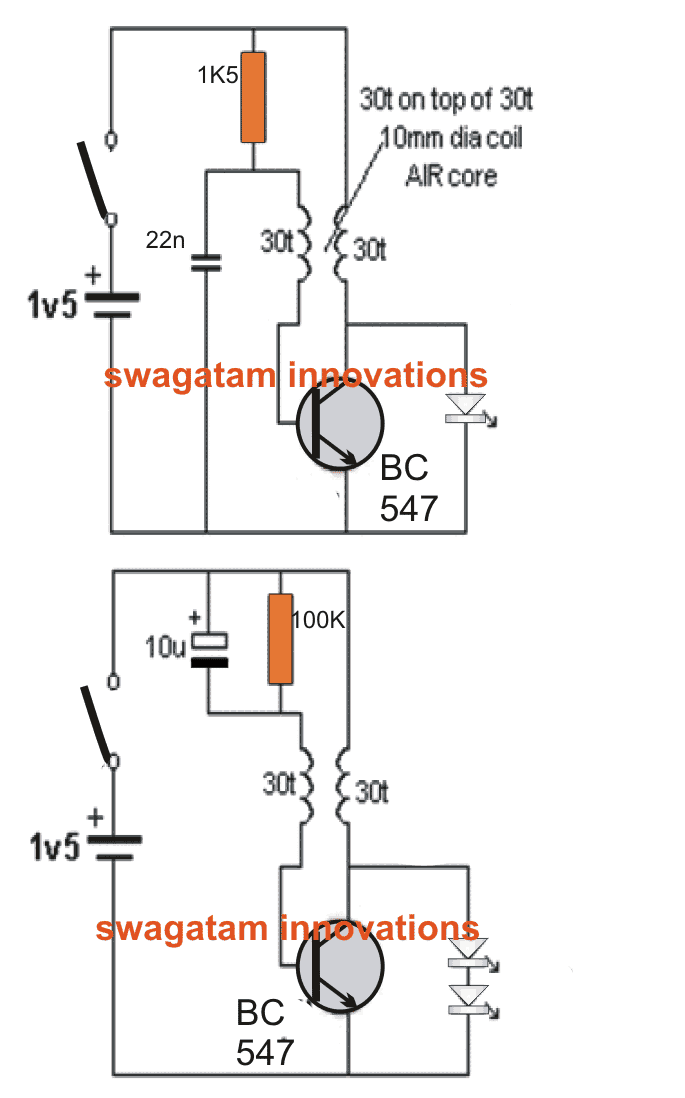
The proposed bike flasher flashes two white LEDs from a single 1.5V cell by using a solitary general purpose transistor, and does not need core for the involved transformer, the main core being the Air itself.
Using Joule Thief Concept
Every Joule Thief circuit uses ferrite rod or toroid core and its turns are wounded on a ferrite material.
With the collapsing magnetic flux it produces an increased voltage, despite the core being Air. As the magnetic field quickly gives away, the circuit renders high voltage in the opposite direction.
The magnetic field which surrounds the coil is efficient to produce energy.
To build this efficient system, wind 30 turns on 10mm of 1/2” dia on a pen or screwdriver and another 30 turns on the top.
Once you build the first circuit, connect it to the wires. Yu can even use 1 or 2 LED. In case it fails to work, just swap the wire which is going to the base.
Add 10u electrolytic and 100k resistor, and remove the 1k5. The circuit is now ready to flash. Remember to use 2 LEDs for the flashing circuit.
Coil Specifications
The 30 turns + 30 turns coil as in the picture takes 20mA for the illumination of 2 LEDs.
Getting maximum energy from the coil becomes possible because of the air at the centre of the coil.
As Air is unable to transfer high magnetic flux, the idea is to provide a larger area (volume) of low flux for the provision of energy.
The larger 20mm coil reduces the current flow from 20mA to 11mA, keeping the same brightness.
Circuit Operation
There are room to improve the performance but the problem lies that the coil gets bigger. It is essential to keep the two 30-turn windings together as the flux from main winding should cut the feedback winding to enable ON state of the transistor HARD.
As the transistor turns on through 100k, the transistor generates magnetic flux in the main winding, cutting the feedback, and with it - a positive voltage is generated connected to 100k and 10u. Thus turns the transistor in ON mode and continues unless turned ON fully.
During this point the magnetic flux does not expand, and the voltage drops to the lowest voltage. This causes the transistor to turn off. The current in the main winding also discontinues abruptly.
The magnetic flux breaks down, producing a voltage in reverse direction, which is higher than the supply, thereby causing the LEDs to illuminate.
This process also channels voltage through the feedback winding, which keeps the transistor in OFF state. As the magnetic flux breaks down, the negative leads’ voltage turns to as low as 10u, keeping the transistor in OFF state.
The 10u discharges by 100k letting the base voltage increase to start the next cycle.
If you are keen to perform an experiment with the aforesaid process, you can definitely do the same since 100k and 1k5 resistors and other necessary parts are available in plenty.
Try to build the first circuit to flash white LED from a single cell. It covers various features and shows the efficiency of a LED, when pulsed briefly with high current.
The two coils in the diagram form a Transformer and illustrate breaking down of magnetic field, producing a high voltage. The 10k and 100k creates a delay in the circuit, thereby producing the flash.
However the Joule Thief circuit fails to perform various experimentation to simplify their circuit. That is one reason to follow ‘birds nest’ arrangement for further experimentation.
Note: Altering the turns to 40t for main winding and 20t for feedback, reduces the current to 8-9mA. However please ensure to keep the turns tighter while winding the wire around.
Submitted By: DhrubaJyoti Biswas
Circuit Diagram


Questions & Answers
Hello and thank you for your time.
I would like to blink a LED with a 5252F IC
I can do it with a ferrite core joule thief but not the IC
I am just starting into this and need some help.
Thank you again
5252F is a boost converter circuit, which will boost a 0.6V to 3V and above. It will not flash an LED. If you are looking for a 3V flasher circuit, you can use the following circuit
Thank you, I believe this is what I was looking for. I think I can integrate this to the output of the 5252f and have a flashing solar garden light. To make the battery last all night.
Thanks, glad it solved the problem for you!
Sir i am a reader of your blog
Sir i have made a circuit of led flasher . I operate this circuit by 15 volt
But … but after 20 minute of running my ic got burn ….. i am using ic 555 . Sir my power supply is 3A 15 volt .
Sir give me a circuit please
Farhan, are you connecting the LED directly with the IC 555 output?, if yes what is the wattage of the LED? and what resistor are you using with it?? please specify these I’ll try to solve it.
Thank you, I'll try it soon. Here is my favorite blog.
you are welcome!
Greeting sir, what is the size of the wire.?
bimo, you can use any thin magnet wire..it's not crucial..