Solar panels are devices which are used for generating electricity from sun light. Solar panels consist of many individual photo voltaic cells arranged in series.
Introduction
Each cell is able to generate a small amount of voltage in response to the incident sun rays over its surface. Arrays of these individual cells are connected in series to form a single solar panel, which results in the generation of a significant magnitude of voltage in the presence of sunlight.
This amazing ability of these devices to convert free and abundant solar energy into electrical power has made it immensely useful in the relevant application.
No doubt, solar panels are gaining popularity at a very rapid pace and can be considered as the devices of the future for replacing conventional methods of generating electricity.
When it comes to personal usage, solar panels can become a difficult parameter to digest. While selecting solar panels, folks tend to depend entirely on the manufacturer and the technical personnel, and therefore are unable to take personal decisions with the devices technical specs and quality.
In this article we’ll discuss some of the basic technical points related to solar panels which will help us to understand solar panels from the core and use them efficiently. The discussed points are though very basic, provides general yet useful inputs regarding these outstanding devices.
As discussed in the above paragraph, solar panels convert direct sunlight incident over their surface into electricity. Since the generated electricity is directly proportional to the striking sunrays, the direction and the intensity of the rays become the main factors affecting the outcomes.
Therefore, the voltage magnitude available across solar panel output terminals may vary according to the intensity and the amount of sun light available over its surface, and varies linearly.
Typically every solar panel is associated with a particular set of technical and electrical specifications, which defines its functioning and application.
The following technical specs can be normally witnessed:
- Optimal voltage,
- Optimal current,
- Maximum voltage,
- Short circuit current,
- Maximum wattage,
- Fuse rating.
As a customer, the parameters which would be particularly important are: optimal voltage, optimal current, short circuit current and the fuse rating.
Though the installations will be handled by the associated engineer, the user should also be aware regarding the operating terms related to these devices. This would greatly help them to analyze, customize and even troubleshoot some of the common faults accompanied with these devices.
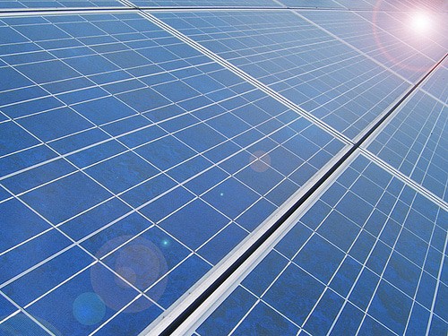
Image Credit - https://cndingwen.en.made-in-china.com/offer/QMsmDPNUHgYy/Sell-285W-Polycrystalline-Solar-Panels.html
Optimal Voltage Specs
Coming back to the specs, optimal voltage refers to the magnitude of voltage that may be acquired from a solar panel under normal conditions; optimal current is also the magnitude of current that’s available from it under the above conditions, that is when the sun light is perpendicular to the surface of the panel with clear skies.
Optimal voltage should always be greater than the minimum required voltage for the application. In fact it should greater than twice the required value. This makes sure that even under gloomy conditions the output from the panel might be just enough for the needs or above the minimum requirements.
During optimal conditions, the excess voltage from the panel is appropriately tailored by the associated voltage regulator such that only the required magnitude reaches the application; normally this voltage will be used for charging an inverter battery.
Maximum voltage can be ignored as it refers to the ability of the panel to produce electricity under maximum artificial forced light conditions, not something related to normal usage.
What is Short Circuit Current
Short circuit current is the magnitude of current which causes the output of the solar panel reach a zero level when its output leads are joined or shorted, a point at which the panel output indicates a zero voltage and fails to operate.
This condition may occur if the voltage spec of the connected load happens to be much less than the solar panel's optimal voltage spec and wherein the load starts drawing huge amount of current from the panel, causing inefficient functioning of the panel, as well as causing damage to itself.
Maximum Fuse Rating for the solar Panel
The maximum fuse rating is the amperage of the fuse wire connected in series with the panels output. This rating should be a shade lower to the above short circuit current rating so that the fuse instantly blows-of before the current can exceed and reach the dangerous short circuit conditions.The maximum wattage spec may also be ignored because once the optimal current and voltage are selected appropriately, the wattage which the product of the above two parameters, automatically adjust with the requirements.
However today’s modern solar voltage regulators and charger associated with solar panels take care of the most critical situations, eliminating short circuit, overload or over voltage situations, safeguarding both the solar panel and the inverter/battery stage which are integrated to the panel for the desired operations.
Although the solar panel may be generating just about enough current for your batteries, it may be quite useless once the sun rays stop reaching the surface of the panel.
To fight against this issue, solar trackersmechanisms are normally employed with solar panels so that the panels keep generating electrical power at the most efficient rates throughout the day irrespective of the sun’s position in the sky.
This also facilitates the incorporation of relatively smaller sized solar panels because now the optimal voltage can be selected just close to the actual requirement and does not need to be twice or thrice than the actual need.


Questions & Answers
Please I have a 5 kva sukam inverter and trying to know rating of capacitor that got burnt completely and the cause. Thanks
Trying to rating of capacitor in a 5 kva sukam inverter, possibly what could have caused the the complete burnt
where was the capacitor connected? provide the exact location….
Hi, I got a Kelvin 1.5kva fixed but it gives buzzing Low Battery alarm intermittently while working, what could be the cause?
keep a voltmeter connected with the battery and check whether the alarm is giving true indications or not, if not then you may have to open the low battery indicator section and diagnose the fault.