In this post I have explained the method of correctly replacing a BJT with a MOSFET, without affecting the final outcome of the circuit.
Introduction
Until MOSFETs arrived in the field of electronics, transistors or BJTs to be precise ruled the power switching circuits and applications.
Though even Bipolar Junction Transistors (BJTs) can not be ignored due to there immense flexibility and low cost, MOSFETs also have certainly become hugely popular as far as switching heavy loads is concerned and due to the high efficiency associated with these components.
However even though these two counterparts may look similar with their functions and style, these two components are completely different with their characteristics and configurations.
Difference Between BJT and MOSFET
The main difference between a BJT and a MOSFET is that, a BJT operation depends on current and needs to be proportionately increased with the load, whereas a mosfet depends on voltage.
But here the MOSFET gets an edge over a BJT, because voltage can be easily manipulated and achieved to the required degrees without much trouble, in contrast increasing current means greater power that's to be delivered, which results in bad efficiency, bulkier configurations etc.
Another big advantage of a MOSFET against the BJT is it's high input resistance, which makes it possible to be integrated with any logic IC directly, no matter how big the load may be that's being switched by the device. This advantage also allows us to connect many MOSFETs in parallel even with very low current inputs (in mA).
MOSFETs are basically of two types, viz. enhancement mode type and depletion mode type. Enhancement type is more frequently used and is the prevalent one.
The N-type MOSFETs can be turned ON or activated by applying a specified positive voltage at their gates while P-type MOSFETs will require just the opposite that is a negative voltage to get turn ON.
BJT Base Resistor vs MOSFET Gate Resistor
As explained above, a the base switching of a BJT is current dependent. Meaning its base current needs to be increased proportionately with increase in its collector load current.
This implies that the base resistor in a BJT plays an important role and must be correctly calculated to ensure that the load is optimally switched ON.
However, the base voltage for a BJT does not matter much, as it can be as low as 0.6 to 1 volts for a satisfactory switching of the connected load.
With MOSFETs it's just the opposite, you can switch them ON with any voltage between 3 V and 15 V, with current as low as 1 to 5 mA.
Hence, a base resistor may be crucial for a BJT but a resistor for the gate of the MOSFET may be immaterial. That said, a low value gate resistor must be included, just to safeguard the device from sudden voltage spikes and transients.
Since voltages above 5 V or up to 12 V are easily available from most digital and analogue ICs, a MOSFET gate can be quickly interfaced with any such signal source, irrespective of the load current.
How to Replace a Transistor (BJT) with a MOSFET
In general we can easily replace a BJT with a MOSFET, provided we take care of the relevant polarities.
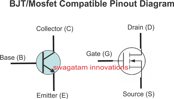
For an NPN BJT, we may replace the BJT with a correctly specified MOSFET in the following manner:
- Remove the base resistor from the circuit because we don't typically need it anymore with a MOSFET.
- Connect the gate of the N-MOSFET directly to the activation voltage source.
- Keep the positive supply connected to one of the load terminals, and connect the other terminal of the load to the drain of the MOSFET.
- Lastly, connect the source of the MOSFET to ground.......DONE, you have replaced the BJT with a mosfet within minutes.
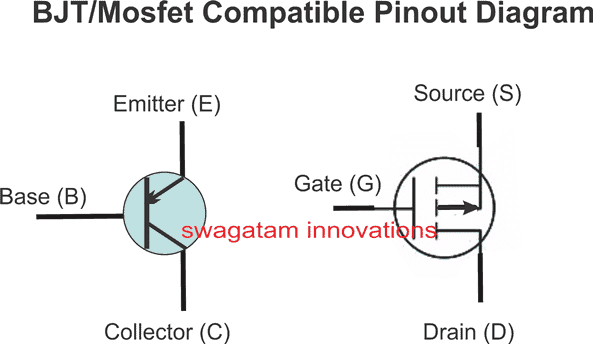
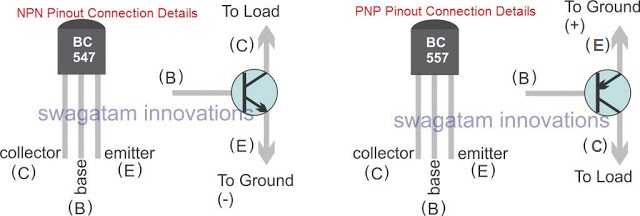
The procedure will remain as above even for a PNP BJT to be replaced with a P-channel MOSFET, you will need to just reverse the relevant supply polarities.
Compatible Pinout Replacement Diagram for PNP BJT with P-Channel MOSFET



Questions & Answers
Dear Swagatam
Thank you for writing this page.
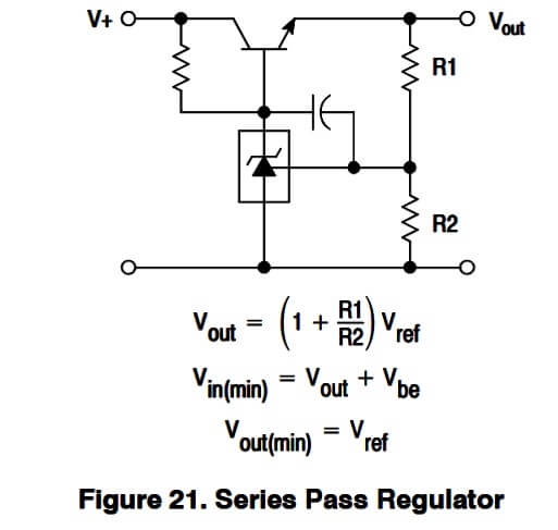
Please take a look at the circuit “Figure 21. Series Pass Regulator” as seen on the page 8 of the Onsemi datasheet of TL431
How can the NPN transistor in that circuit be replaced with a MOSFET?
Dear SA,
According to me you can directly replace the E, B, C, of the BJT with the S, G, D of a MOSFET, however a BJT drops around 0.6V at its emitter, but a MOSFET may drop a lot higher than that at its source.
I had connected Series Pass Regulator with a TIP41C and It has been working: Vin 18.7V, Vout variable between 3.5V to 18V. The components are 220Ω as base resistor, 43.77K as R1, 100K potentiometer as R2, and without capacitor.
Yesterday I replaced TIP41C with an IRF9540N MOSFET. Turning the potentiometer varies the Vout only from 18.7 to 18.2. It seems that this Series Pass Regulator did not work with only replacing the BJT with MOSFET.
Why my circuit can vary the Vout by only 0.5V? What is wrong with it?
IRF9540N is a P-channel MOSFET, please replace it with IRF540 or any other N-channel MOSFET…and then check the results…
Hello Swagatam

I used an AP40N03GP N-channel MOSFET. The output is now variable between 3.7 to 17.2 volts.
(As I in the previous comments said, the circuit is the one in the “Figure 21. Series Pass Regulator” on the page 8
The input voltage is 18.7V. The components are 220Ω as Gate resistor, 43.77K as R1, 100K potentiometer as R2. I did not use any capacitor.)
The problem now is “shortage of output current” that causes voltage drop. The Input is supplied by a SMPS power supply with 18.7 volts and 3.4 A output. 18.7×3.4=63.58 watts. Let’s say 60 watts. When I adjust the output of the circuit on 12.09 volts, and connect a 42-watt 12-volt lamp to it, the output voltage drops to 11.74V. When I connect a 60-watt 12-volt lamp to it, the output voltage first drops to 0.1 to 0.2 volts and of course cannot turn on the lamp, but then rises to a fluctuating voltage between 2 to 3 volts and the lamp begins to flash (turns on and off).
Why cannot this circuit output even 3.5 A (42-watt 12-volt lamp) without dropping the voltage about 0.35 volts, let alone output 5 A (60-watt 12-volt lamp), whereas the input is at least 60 watts (18.7×3.4=63.58 watts)?
Hi SA,
I think it is happening due to the internal resistance of the pass transistor, as we know BJTs can be hugely inefficient in terms of current transfer, as these are current dependent devices.
Please try replacing the pass transistor with a Darlington BJT such as TIP122, and then check the results, or simply upgrade your existing pass power BJT with another NPN such as 2N2222 to form a Darlington pair….and then check the results. Let me know how it goes.
…Just wanted to add, TIP122 cannot handle 3.5 amps unless mounted on a very big air cooled heatsink, so better go with TIP142 (with heatsink) or a combination of 2N3055 and 2N2222 Darlington pair.
My last comment, #212460 (in reply to your #212033) was about using a N-channel MOSFET (AP40N03GP) not about using BJTs. But your reply in #212465 and #2124656 is about using BJTs. Do you imply not to use a MOSFET?
Hi SA, I am really sorry, seeing the BJT in the diagram, I just forgot that your question was based on a MOSFET, OK, here’s the correct answer now….
Since this is a linear regulator, so there is no power conversion taking place. The current through the MOSFET and load will be approximately the same as the input current.
With 18.7V input and 12V output, at 3.4A the MOSFET has to drop about:
18.7 – 12 = 6.7V
So the MOSFET itself will dissipate around:
6.7 * 3.4 = 22.8 watts, and the load will receive around:
12 * 3.4 = 40.8 watts
So yes, in theory your 3.4A SMPS can give around 40W at 12V through this linear regulator, provided the SMPS can actually maintain 18.7V at 3.4A.
But your 42W lamp needs:
42 / 12 = 3.5A
This is already slightly above the 3.4A rating of your SMPS. And most important aspect is that because it is an incandescent lamp, the filament is cold at the start, its resistance is much lower, so the initial current can be several times higher than the normal 3.5A.
Therefore the SMPS could be going into current limiting or hiccup protection mode. That could be why you see the output falling from 12.09V to 11.74V.
For the 60W lamp, the normal current is about 5A, which is far above your 3.4A SMPS rating. During startup it can demand even more. So the SMPS protection will most probably shut down, recover, shut down again, etc. This is exactly the kind of behaviour that can make the lamp flash.
There is also one important test I would suggest.
Please don’t measure only the regulator output. Connect the 42W lamp and measure the voltage directly at the SMPS output terminals at the same time.
If the SMPS voltage itself falls significantly below 18.7V when the lamp is connected, then the main limitation is the SMPS.
If the SMPS remains close to 18.7V but the regulator output falls badly, then we need to investigate the regulator itself — MOSFET heating, gate drive voltage, source/drain connection, wiring resistance, PCB tracks, or the TL431 control circuit.
Also check the voltage between MOSFET gate and source while the 42W lamp is connected. This is important because the AP40N03GP may require sufficient VGS (+15V) to conduct the required current.
And also remember about the MOSFET heating. At around 3.4A and 12V output, it can already be dissipating roughly 23 watts. So it needs a proper heatsink. If the MOSFET gets very hot, its behavior can also change and the output may start dropping.
So I would first check these three voltages under the 42W load:
SMPS output voltage = should remain close to 18.7V
Regulator output voltage
MOSFET VGS voltage
These three measurements will tell us where the actual problem is.
…and yes, adding to my previous comment, alternatively you could definitely try a Darlington BJT such as TIP142 (with heatsink) and test the results….
The VGS(th) parameter of IRF540 is “minimum: 2.0V; maximum: 4.0V (conditions: VDS = VGS, ID = 250 μA)”.
Does this relates to what you said “a MOSFET may drop a lot higher than that at its source”, and means that IRF540 will cause 2.0 to 4.0 volts drop at the output of the Series Pass Regulator?
Yes, that’s correct!!
Most BJTs have low Beta and this limits the current that they can deliver (when saturated) in the output of that circuit.
Do you know if a MOSFET is affected by Beta or another such limitation that will limit the output current in that circuit?
MOSFETs efficiency is basically determined by their RDSon values, which is the minimum resistance value across drain and source of the MOSFET. Other factor is the voltage Vgs which must be above the minimum threshold, as specified in its datasheet.
“IRF9540N” MOSFET has the following specs:
RDS(on): Max. 0.117Ω (Condition: VGS= -10V, ID= -11A)
VGS(th): Min. -2.0V; Max. -4.0V (Condition: VDS = VGS, ID= -250µA)
Do you know how efficient is “IRF9540N” compared to other N-channel mosfets?
Sure, just compare its RDSon with other similar MOSFETs…you will be able to check which one has the lowest RDSon value, that one will be the most efficient one…
How would you manage to replace the bjt transistor with another type of Device?
What type of device are you referring to?
any replacement for D1 292 transistor. that might be similer to it
You can Google 100V 1 amp NPN transistor, you may find many good options.
Looooongest time sir.
I have been searching for your contacts or your site. I am happy I got you today. You helped me to understand a lot in the past
Thank you Ik, I am always happy to help….. All the best to you.
Hi SwagatamI sent you a msg in facebook asking for help with replacing mrf486’s and mrf422’s i sent it there because i attached a schematic if you could please help thank you
Thank you John,
According to me you cannot replace MRF486 with a MOSFET. You can try searching for 30 MHz 20 Amp Rf NPN power transistor, and find a suitable equivalent for the replacement.
maybe what i’m looking for is LDMOS not MOSFET’S ?
I think the basic replacement principle will be the same, just as any other mosfet, since LDMOS is also a type of MOSFET.
thanks for the reply , yes i been searching and found nothing even close to mrf486’s
i’m thinking they were only made for this one radio only
the next version of this radio that came out had mosfets in it
i compared both schematics to these radios and the pa unit circuit look pretty close to the same design
the thing is i don’t know that much as to how to make the proper modifications to make it work , i never tried it before
Yes, I agree, I too tried searching for “30 MHz power transistor” but could not find anything useful. Unfortunately in RF circuits a BJT cannot be easily replaced with a mosfet.
What ordinary transistor do I replace for Darlington 2SD1298 or D1298?
You can use BU406D and MJE13003 in Darlington pair.
Or you can search for any 400V 10 amp transistor and 400V 1 amp transistor and combine them to make a Darlington pair.
Hi sir how can i connect a universal power module to my smps 30amp cause i cannot get 13009 transistors on my local market
AS far as I know universal power module has a power mosfet or transistors with 3 wires corresponding to the 3 leads of the power device. You can carefully check these wire according to the given user manual and then connect these wires across the respective tracks of the SMPS PCB.
However I would strongly recommend replacing with a discrete transistor instead of a power module.
Hi,
Can you please review the MOSFET symbols given and the type of MOS labeled?
Irfp448n
Good day, i would like to know if its possible to change the 13009 transistors in a smps (cheap 12v 30amp) to N-Channel mosfets, the transistors are driven by a gate transformer. If its possible can you give me a example schematic of how to change it if possible, here is a schematic of the smps.
I would greatly appreciate any help you can give me.
Regards
Darius
Good day eant to add, primary has 33turns then a center tap with another 33turns after.
Then the secondary has two separate 9turns without a enter tap and then a feed back with 2 turns
The primary and secondary windings has a copper thickness of 0.4mm and the feedback is 0.65mm.
Regards
Darius
Hi, How is this transformer wired, which IC is used? I will need more information regarding your question to figure out the issue?
Hello, the IC is a TL494 and its a half-bridge topology, i see on my first post that i forgot to add the link to the schematic, i’ll add the link in the end.
(imajeenyus.com/electronics/20151028_smps_variable_voltage/index.shtml) or type in on google s-400-12 supply schematic and check on the images.
I hope this help, it has the full schematic and how the gate drive transformer is winded and the main transformer aswell.
Regards and thanks again
Darius
Thanks for the schematic, This is an SMPS circuit where the transformers are the most critical elements of the circuit. You can rewind it but the winding details must be exactly similar to the original data….you cannot change the data with your own specifications.
Hi, according to me a an 13009 BJT cannot be replaced with a MOSFET in an SMPS circuit.
Thank you for the fast reply, is there no way to rewind the gate drive transformer if I’m correct the transformer is wind in a 4:1 ratio and has a feedback winding aswell, the primary winding is 10v peak to peak and secondary is 2.2v peak to peak, so if you rewind it 1:1 will it work?
Thanks
Regards
Darius
Without seeing the full schematic it can be difficult for me to provide a useful suggestion.
Hello with respect sir
I have long range cordless phone senao-258 star handy 264MHz 350mW rf power output, transistor is blt50 but i want more power near 2 or 4 watts…
Is it possible to replace ldmos aft504???or please guide me
And another question is i know uhf mosfet kgf-1305, but not found in my area please tell me what are power mos-fet work very similar like kgf-1305
Hello Babak, I could not find any data regarding the mentioned mosfets, so cannot provide any suggestions. You can try other variants such as irf540 etc.
Hi, I was wanting to try and replace the Darlington Transistor a circuit with an FET or MOSFET. I am not sure if I should do this or what changes would need to be made. It charges the capacitors when plugged in, then turns off when the capacitors discharge through the coils attached to the output with the momentary on switch. The capacitors would discharge for 20ms to maybe 200ms to pulse the coils, but don’t go through the FET. It is the initial charge surge current I need to worry about. I can’t seem to attach an image, but the power source is 12-20V, the current goes through the Darlington right to the + end of a 4700uF capacitor. When the capacitors discharge through a diode, the current to the base of the transistor goes to 0, it switches off, and the diode protects the transistor as the current has to go to the coil. The button on the coil is released, that pat of the circuit is open again, voltage goes to the transistor, and current flows to the base, so it switches on again and charged the capacitor again. Thanks for any help.
Hi, if your load is on the collector pin of the BJT, then you can replace the BJT with a MOSFET and place the load on its drain, however, if the load is connected at the emitter of the BJT then MOSFET might require the load to be placed on its source pin, which might alter the results.
Alright my specs
Are jfet j201 , or any 2n5457 series
I searched for depletion mode that could replace them but couldn’t find one only found 2n7000 unfortunately it enhance mode MOSFET.
Can you please suggest some to me sir
You will have to also provide the required current and voltage specifications of your MoSFET or the JFET, to be able to search an equivalent
Hello swag, please what is the main point to take, considering replacing a MOSFET?
Hello Kenkenny, The power rating of the new device must be equal or higher than the original device. The pinouts must be correctly configured. The voltage and current spec of the new device must be equal or higher than the original device.
Interesting , I really love this it has enlighten me more , in dealing with related components,
Thanks so much for this ,help my novice understanding
Here is my question
JFET are very rare at my Local store i found it highly frustrating. It has serve as barrier to my Inspired DIYs
is there a possible replacement or alternative
I found they good for guitar sound effect , amplifiers am working towards phaser effect (using opamp LFO) but i still found i need those jfet
Please help my novice knowledge
Glad it helped you! You can definitely replace JFET with a depletion mode MOSFET. There are plenty of variants online, you can select one of them depending on the VDS and ID of your JFET specs.
Thanks for the reply, that is what I thought but I have been watching a Utube video of an attiny drive the gate of P channel mosfet to blink an led and it had no pull down resistor so I was confused
Pull down resistor is recommended for MOSFETs for ensuring a failproof working, but it is not mandatory if the switching input is from a high quality logical source.
Am I correct in thinking if I replace a pnp bjt (BD136) with a mosfet I will still need a pulldown resistor on the gate to enable the mosfet to turn off?
For MOSFETs it is recommended to have a permanent resistor across their gate/source terminals.
Hi Swagatam!
I have an amplifier with power transistor sc5200 and sa1943 with 45-0-45v supply, i would like to convert it to mosfet. Do you have suggestions what pair of mosfet will be good? thanks!
Hi Nitsya, in amplifiers it may not be so easy to replace BJTs with MOSFeTs, since a BJT may start conducting fully with base potential as low as 1 V while MOSFETs may require 6 to 12 V.
Oh! Thanks alot Swagatam.
Hello Swagatam, can I replace D718 & B688 in audio amplifier. Any recommended MOSFETs,also do I need to replace BD139 & BD140 to use 45-0-45 Volt 8 Amp transformer.
Hello Ajay, the first two transistors are 120 V 8 amp NPN/PNP pairs, you can replace them with a matching pair having the same V and I specs.
You can use BD139/BD140 with 45 V supply
Hello Swagatam,
Thank you very much for the response, any suggestions for MOSFETs as I want to increase the wattage of the amplifier.
Regards,
Thanks Ajay, I can’t suggest much about the MOSFEts, because it can be a bit complex to replace BJTs with MOSFETs in an audio amplifier design
Thank you Swagatam, let me try som experiments, if successful will update
Sure, no problem!
2SC4054 BJT Transistor Failed Need a Replacement
I have an SMPS using a 2sc4054 BJT transistor that failed, since that transistor is no longer available I would like to replace it with a Mosfet. What Mosfet should I use and what other modification should be made to the circuit so the Mosfet receives the right gate voltage ? here is the link to the power supply circuit diagram
Try MJE13005 and see if that works or not.
Hi,
I want to change my BJT BC547 with a MOSFET, but i dont know which MOSFET should i choose. Can you help me with it?
Hi, you can try BS170 mosfet
Thank you for your help
Can I replace a K10A60 N Channel mosfet with a D13007 npn transistor
Please check and compare the VDSon and ID of the two devices, if they are similar then you ca interchange them…
Thanks for sharing such a beautiful article. It’s very helpful to me. Please keep sharing more about mosfet transistor
hi what could i replace a irfz34n with could i used a irf 44n
Please check the datasheet of the two and compare their VDs and ID rating, it will clarify your doubt.
What is the alternative transistor RFP50N06 for a 300W inverter?
IRFZ44N
Educational article sir
Hi mr Mr swagatam,if i had a circuit that need NBJT,
Q1: can i replaced it with any NFET if from datasheet that NFET have my own requirements such as voltage, current, temperature?even more great than NBJT.
Q2: Is there any transistor built in oscilators?
thanks for any advice.
Thanks Skhan, yes you can replace a BJT with an FET, just make sure their polarity are identical, use a low value resistor at the gate and make sure the gate has at least 10V for the switching
for transistor oscillator you can refer to this post:
https://www.homemade-circuits.com/easy-two-transistor-projects-for-school-students/
Hi Swagatam, I have to replace all my BJT from all my PCBs.
Which N-ch Mosfet do you advise me to change the MMBT2222L (NPN)?
and…
Which P-ch Mosfet do you advise me to change the MMBT2907AL (PNP) ?
Considering:
– They be economical
– All my BJT are SOT-23 package, thus Mosfet must be also.
– Both BJT type are working under TTL logic, so gates will be drive directly by PIC microcontroller 5v. And Load 12v (no need much Amp).
Hi Yany,
I would like to know the reason for changing those devices, because BJTs have their own significance depending on the application area, and should not be changed with a MOSFET when they are well suited for the need.
Moreover a MOSFET will not turn ON efficiently at 5 V. I think in your case the BJTs are perfectly fine!
Hi Swagatam,
The reason is just what you said, to reduce dependencies and look for best commutation efficiency, and also to reduce PCB sizes for my next designs.
And to improve it for my next design, which Mosfet would you advise me for I begin testing?
(considering all the previous, and turn ON efficiently at 5v)
Hi Yani,
you can try this for the 2222
https://www.onsemi.com/pub/Collateral/FDB8860_F085-D.PDF
or you could try this for a 2-in-1 package
http://ww1.microchip.com/downloads/en/DeviceDoc/tc6215.pdf
HI BROTHER THIS METH ODE NOT WORKING FOR ME BY REPLACING 2N 3055 WITH IRFP240
Hi, it will surely work, but remember MOSFeTs are very sensitive, and will blow without a hint, not like BJTs. Please specify what kind of driver are you using for the gate drive, I’ll try to help!
Good evening Swagatam Ji.
I need one more clarification.
Let me give 24 dc supplies to solar-e-rickshaw-circuit (or )
I have to reduce 12volt dc by the way of 12volt regulator.
If I have to give only 12volt dc supply then please give me simple
and trouble free solution to get 12volt from 24volt battery supply.
(I have crossed my age about 68years. I am just helping my friends by the help of fresh EEE students )
Thanks.
sakthivel.
Hello Sakthivel ji,
you can use 24V, and use a 7812 IC for converting it to 12V only for the IC. Meaning, the motor can be tied to +24V, but the IC 555 must be fed from a 7812 IC connected with the 24V source
Thank you very much Swagatamji for your suggestion!
sakthivel.
You are welcome sakthivel!
TIP142/ IRF540 Mosfet compatiable pinout diagram please
gate will go to IC 555 output, source will go to the ground line, drain to the motor:
Just wanted to point out that “triggered” is not a suitable description for turning on a BJT or FET, since it has a very specific meaning regarding semiconductors, and is used instead to describe the activation of UJTs, SCRs, DIACs, TRIACs, etc. You “turn on” or “switch on” a BJT or FET, you don’t trigger it.
Thank you for your suggestion!