In this post I will show how to construct an Arduino automatic street light dimmer circuit, which can reduce its brightness when no vehicle is passing in the road to save power.
Overview
We will be exploring the methodology of sensing the vehicle or human being without false detection which may occur due to animals and also the protocol for dimming light without wasting energy.
Street lights help the vehicles to guide along the road, but during late night hours, most of the roads will be empty and still all the street lights illuminate till morning.
Due to the illumination of street lights all night even when the road is empty, it is not worth to light the street lamps and the cost due to energy consumption directly affect the local government.
To overcome this issue in smart way, we can reduce the brightness of the street lamps to desire level and only illuminate in full brightness when vehicles or human being pass by.
This may help the government to reduce expenditure on power and also save lot of energy which could be used for other energy demanding purposes.
The proposed idea to detect activity on the road, utilizes ultrasonic sensor which can measure the distance between the sensor and the obstacle, in this case the obstacles are vehicles or human beings.
When a vehicle comes into the range of the sensor, it does some mathematical calculations to determine the distance between the vehicles and sensor, if the vehicle is confirmed to be below the pre-determined range; the on-board microcontroller will light the street lamp at maximum brightness.
The street light will illuminate at maximum brightness for a pre-determined amount of time and reduce its brightness if no vehicles or human beings are detected further.
By now the objective of this project would have cleared. Let’s dive into circuitry of the proposed setup.
Circuit Operation
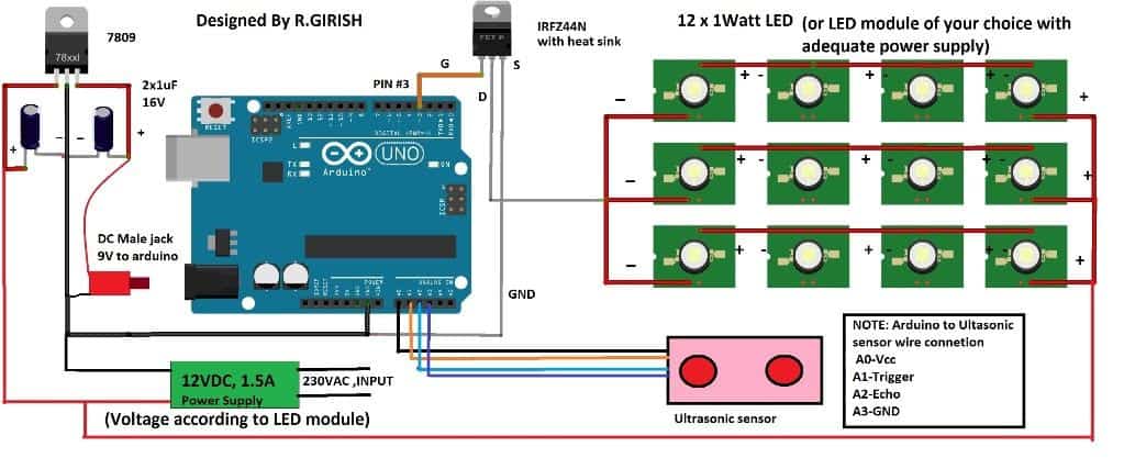
The automatic street light dimmer circuit consist of Arduino which is the brain of the project, an ultrasonic sensor for detecting vehicles or human beings. A 9V regulator is provided for powering the arduino microcontroller board and a MOSFET for driving the LEDs which consumes few amperes at peak brightness.
The LED module and power supply for the setup must be selected carefully so that there will be adequate power available for the whole circuit and does not overload the power supply.
The LED module can be homemade one which is shown in schematic or may be purchased for market, but before constructing or getting one form market make sure to calculate the voltage and current requirements for the power supply.
The power supply may be an SMPS or constructed using transformer, rectifier and voltage regulator.
The LED reduces its brightness by using PWM. The PWM is square wave, it turns on and off supply to LED rapidly with well determined on and off width in a single cycle. The width of the on and off time determine the brightness of the LED.
When the street light switches to full brightness the supply to LED will have no pulses and steady DC will be supplied.
The whole setup can be implemented as shown below:
Setup Diagram
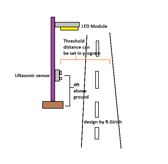
The ultrasonic sensor is elevated around 3.5ft to 4ft above the ground; this is done so that it only detects vehicles and human beings, since their average height is around the same and when dogs or cats or any other animals which usually roam around the city will not trigger the street light to maximum brightness.
The animals which live and roam around the city are below 3.5ft tall.
The sensor height may be adjusted to operate at optimum level as described in the above picture.
The threshold distance can be controlled in the program.
When the Arduino detects the obstacle detected below pre-determined distance the LED lights go peak brightness.
Program Code:
//-------------------- Program developed by R. Girish --------------------//
// Ultrasonic sensor connections
const int trigger = A1; // Trigger pin of ultrasonic sensor
const int echo = A2; // Echo pin of ultrasonic sensor
// Power pins for ultrasonic sensor (provided through Arduino)
int vcc = A0; // VCC pin for sensor
int gnd = A3; // GND pin for sensor
// Output load
int LED = 3; // PWM pin connected to LED or lamp driver
// Variables used for distance calculation
long Time; // Stores echo pulse duration
float distanceCM; // Raw distance in cm
float distanceM; // Raw distance in meters
// User settings
float distance = 100; // Threshold distance in cm
int dim = 28; // Minimum brightness level
int bright = 255; // Maximum brightness level
// Final calculated values
float resultCM;
float resultM;
void setup()
{
// Configure I/O pins
pinMode(LED, OUTPUT);
pinMode(trigger, OUTPUT);
pinMode(echo, INPUT);
pinMode(vcc, OUTPUT);
pinMode(gnd, OUTPUT);
// Start serial communication for monitoring
Serial.begin(9600);
}
void loop()
{
// Powering the ultrasonic sensor
digitalWrite(vcc, HIGH);
digitalWrite(gnd, LOW);
// Ensure trigger pin is LOW before sending pulse
digitalWrite(trigger, LOW);
delay(1);
// Send 10µs trigger pulse
digitalWrite(trigger, HIGH);
delayMicroseconds(10);
digitalWrite(trigger, LOW);
// Measure echo pulse width
Time = pulseIn(echo, HIGH);
// Convert time into distance
distanceCM = Time * 0.034; // Speed of sound calculation
resultCM = distanceCM / 2;
resultM = resultCM / 100;
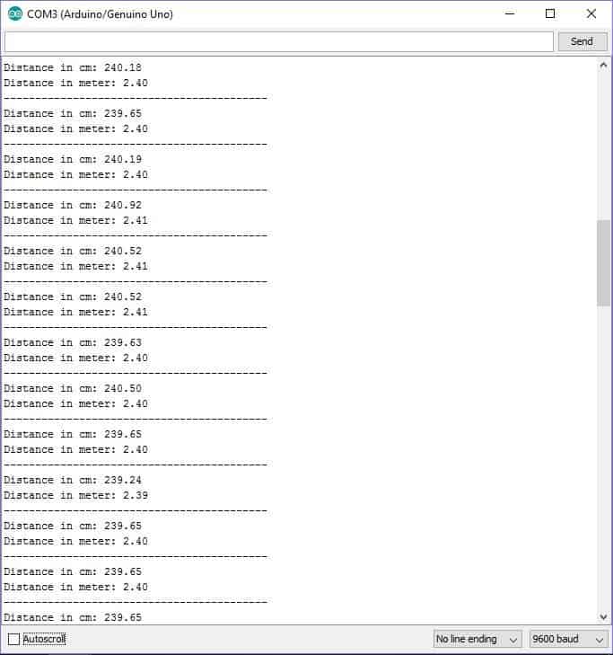
// Display distance values on Serial Monitor
Serial.print("Distance in cm: ");
Serial.println(resultCM);
Serial.print("Distance in meter: ");
Serial.println(resultM);
Serial.println("------------------------------------------");
// If object is within the threshold distance
if (resultCM <= distance)
{
analogWrite(LED, bright); // Full brightness
delay(10000); // Hold ON for 10 seconds
}
// If object is beyond the threshold distance
if (resultCM >= distance)
{
analogWrite(LED, dim); // Dim brightness
}
delay(100); // Small delay for stability
}
//-------------------- Program developed by R. Girish --------------------//
NOTE:
• The threshold distance can be adjusted by replacing the Value with your own.
float distance = 100; // set threshold distance in cm
The value must be entered in centimetre; the maximum value can be 400 to 500 cm or 4 to 5 meter.
• The dimming of the light can be adjusted by using
int dim = 28; // adjust minimum brightness
255 is maximum brightness 0 is lights off.
We can also witness the distance between the sensor and the obstacle in serial monitor.
Upgrading the Code for Enabling Automatic Day, Night ON/OFF of the Lamp
Program Code
//-------------------- Program developed by homemade-circuits.com --------------------//

// Ultrasonic sensor connections
const int trigger = A1;     // Trigger pin of ultrasonic sensor
const int echo    = A2;     // Echo pin of ultrasonic sensor

// Power pins for ultrasonic sensor
int vcc = A0;              // VCC pin for sensor
int gnd = A3;              // GND pin for sensor

// LDR connection
int LDR = A4;              // LDR connected to analog pin A4

// Output load
int LED = 3;               // PWM pin connected to LED or lamp driver

// Variables used for distance calculation
long Time;
float distanceCM;

// User settings
float distance = 100;      // Detection distance in cm
int dim    = 28;           // Dim brightness
int bright = 255;          // Full brightness

// LDR setting (must be calibrated using Serial Monitor)
int LDR_threshold = 73;

// Final calculated value
float resultCM;

void setup()
{
  pinMode(LED, OUTPUT);
  pinMode(trigger, OUTPUT);
  pinMode(echo, INPUT);
  pinMode(vcc, OUTPUT);
  pinMode(gnd, OUTPUT);

  Serial.begin(9600);
}

void loop()
{
  // Read LDR value
  int LDR_value = analogRead(LDR);

  Serial.print("LDR Value: ");
  Serial.println(LDR_value);

  // -------- DAY TIME CONDITION --------
  if (LDR_value > LDR_threshold)
  {
    analogWrite(LED, 0);        // Light OFF during daytime
    delay(500);
    return;                     // Skip ultrasonic sensing
  }

  // -------- NIGHT TIME CONDITION --------
  digitalWrite(vcc, HIGH);
  digitalWrite(gnd, LOW);

  // Trigger ultrasonic pulse
  digitalWrite(trigger, LOW);
  delayMicroseconds(2);
  digitalWrite(trigger, HIGH);
  delayMicroseconds(10);
  digitalWrite(trigger, LOW);

  // Measure echo pulse
  Time = pulseIn(echo, HIGH, 25000);   // Timeout added for stability

  // Convert time to distance
  distanceCM = Time * 0.034;
  resultCM   = distanceCM / 2;

  Serial.print("Distance in cm: ");
  Serial.println(resultCM);
  Serial.println("--------------------------------");

  // -------- OBJECT DETECTED --------
  if (resultCM > 0 && resultCM <= distance)
  {
    analogWrite(LED, bright);   // Full brightness
    delay(10000);               // Light ON time
    analogWrite(LED, 0);        // Turn OFF after delay
    return;                     // Restart loop
  }

  // -------- NO OBJECT DETECTED --------
  analogWrite(LED, dim);        // Dim light during night

  delay(200);
}

//-------------------- Program developed by homemade-circuits.com --------------------//
LDR cannot be connected directly to Arduino alone, it must be used with one fixed resistor, so voltage divider is formed, otherwise reading will not work.
Components Needed
- 1 × LDR
- 1 × fixed resistor (10k is ideal, anything from 10k to 47k works)
Step By Step Wiring
Take one lead of the LDR. Connect it directly to +5V of the Arduino.
Then, take second lead of the LDR and connect it to analog pin A4 of the Arduino.
Connect the fixed resistor (10k). One end of resistor goes to A4, the same point where LDR second lead is connected. Other end of resistor goes to GND of the Arduino.
That is it….
Now A4 remains connected between LDR and resistor and senses light level, so reading changes.
How This Works Electrically
During daytime, or bright light, LDR resistance becomes low. Then voltage at A4 goes high, and so Arduino reads large analog value.
During night time, or darkness, the LDR resistance becomes high, then voltage at A4 goes low. so Arduino reads small analog value.
Code Logic Matching
If LDR_value > threshold… then Day is detected, and then Lamp is turned OFF.
If LDR_value < threshold…. then Night is detected, then Lamp is turned ON and is ACTIVE.
Practical Tip
After wiring, please upload the code, then open Serial Monitor and note LDR readings for the following:
- Bright sunlight
- Indoor light
- Complete darkness
Next, set the following line in the Arduino code accordingly:
int LDR_threshold = (day_value + night_value) / 2;
If you have any further questions regarding this Arduino based automatic street light dimmer circuit feel free to ask in comment section.


Questions & Answers
sir i dont know whats happen, i tried all others code thats are working, only this one giving issue, can you give me one favor plz, which you are pasting in aurdino ide. can you pste here in reply plz.
others all code are with diffrent colors. but this one has only green color.
Hi Ghulam,
Please see this video:
https://www.homemade-circuits.com/wp-content/uploads/2026/01/Arduino-sketch.mp4
//-------------------- Program developed by homemade-circuits.com --------------------//// Ultrasonic sensor connections
const int trigger = A1; // Trigger pin of ultrasonic sensor
const int echo = A2; // Echo pin of ultrasonic sensor
// Power pins for ultrasonic sensor
int vcc = A0; // VCC pin for sensor
int gnd = A3; // GND pin for sensor
// LDR connection
int LDR = A4; // LDR connected to analog pin A4
// Output load
int LED = 3; // PWM pin connected to LED or lamp driver
// Variables used for distance calculation
long Time; // Stores echo pulse duration
float distanceCM; // Raw distance in cm
// User settings
float distance = 100; // Threshold distance in cm
int dim = 28; // Minimum brightness
int bright = 255; // Maximum brightness
// LDR setting
int LDR_threshold = 500; // Adjust this value for day/night detection
// Final calculated value
float resultCM;
void setup()
{
// Configure I/O pins
pinMode(LED, OUTPUT);
pinMode(trigger, OUTPUT);
pinMode(echo, INPUT);
pinMode(vcc, OUTPUT);
pinMode(gnd, OUTPUT);
// Serial monitor
Serial.begin(9600);
}
void loop()
{
// Read LDR value
int LDR_value = analogRead(LDR);
Serial.print("LDR Value: ");
Serial.println(LDR_value);
// -------- DAY TIME CONDITION --------
// If sufficient daylight is present, turn OFF the lamp
if (LDR_value > LDR_threshold)
{
analogWrite(LED, 0); // Lamp OFF during daytime
delay(500);
return; // Skip ultrasonic sensing
}
// -------- NIGHT TIME CONDITION --------
// Powering the ultrasonic sensor
digitalWrite(vcc, HIGH);
digitalWrite(gnd, LOW);
// Trigger ultrasonic pulse
digitalWrite(trigger, LOW);
delay(1);
digitalWrite(trigger, HIGH);
delayMicroseconds(10);
digitalWrite(trigger, LOW);
// Measure echo pulse width
Time = pulseIn(echo, HIGH);
// Convert time into distance
distanceCM = Time * 0.034;
resultCM = distanceCM / 2;
Serial.print("Distance in cm: ");
Serial.println(resultCM);
Serial.println("------------------------------------------");
// Object detected within range
if (resultCM <= distance) { analogWrite(LED, bright); // Full brightness delay(10000); // ON duration }// No object detected if (resultCM >= distance)
{
analogWrite(LED, dim); // Dim mode
}
delay(100);
}
//-------------------- Program developed by homemade-circuits.com --------------------//
sir i tried again. now i put int LDR_threshold =73 instead of
int LDR_threshold = 500; now in day time lightnis completly off, and night time light not dim. its totly off, when object found light is bright on. and its not off…continusally on…only day time its off. it should be off as per delay time. plz check where i am wrong?
Ghulam, please try the following code, and let me know:
//-------------------- Program developed by homemade-circuits.com --------------------//// Ultrasonic sensor connections
const int trigger = A1; // Trigger pin of ultrasonic sensor
const int echo = A2; // Echo pin of ultrasonic sensor
// Power pins for ultrasonic sensor
int vcc = A0; // VCC pin for sensor
int gnd = A3; // GND pin for sensor
// LDR connection
int LDR = A4; // LDR connected to analog pin A4
// Output load
int LED = 3; // PWM pin connected to LED or lamp driver
// Variables used for distance calculation
long Time;
float distanceCM;
// User settings
float distance = 100; // Detection distance in cm
int dim = 28; // Dim brightness
int bright = 255; // Full brightness
// LDR setting (must be calibrated using Serial Monitor)
int LDR_threshold = 73;
// Final calculated value
float resultCM;
void setup()
{
pinMode(LED, OUTPUT);
pinMode(trigger, OUTPUT);
pinMode(echo, INPUT);
pinMode(vcc, OUTPUT);
pinMode(gnd, OUTPUT);
Serial.begin(9600);
}
void loop()
{
// Read LDR value
int LDR_value = analogRead(LDR);
Serial.print("LDR Value: ");
Serial.println(LDR_value);
// -------- DAY TIME CONDITION --------
if (LDR_value > LDR_threshold)
{
analogWrite(LED, 0); // Light OFF during daytime
delay(500);
return; // Skip ultrasonic sensing
}
// -------- NIGHT TIME CONDITION --------
digitalWrite(vcc, HIGH);
digitalWrite(gnd, LOW);
// Trigger ultrasonic pulse
digitalWrite(trigger, LOW);
delayMicroseconds(2);
digitalWrite(trigger, HIGH);
delayMicroseconds(10);
digitalWrite(trigger, LOW);
// Measure echo pulse
Time = pulseIn(echo, HIGH, 25000); // Timeout added for stability
// Convert time to distance
distanceCM = Time * 0.034;
resultCM = distanceCM / 2;
Serial.print("Distance in cm: ");
Serial.println(resultCM);
Serial.println("--------------------------------");
// -------- OBJECT DETECTED --------
if (resultCM > 0 && resultCM <= distance) { analogWrite(LED, bright); // Full brightness delay(10000); // Light ON time analogWrite(LED, 0); // Turn OFF after delay return; // Restart loop }// -------- NO OBJECT DETECTED -------- analogWrite(LED, dim); // Dim light during nightdelay(200); }//-------------------- Program developed by homemade-circuits.com --------------------//
hi sir, sir plz support me to diagnose my isue. if i am using with ardino uno board on bread board. its working fine. but if I am using with aurdino nano on zero board soldering. in day time light not completetly off. its dim but more than night time dim value 28. i soldered on zero board with aurdino nano. is there any need to be changes for aurdino nano?
i am using this same code on both aurdino bord.
// Ultrasonic sensor connections
const int trigger = A1;
// Trigger pin of ultrasonic sensor
const int echo = A2;
// Echo pin of ultrasonic sensor
int vcc = A0;
// VCC pin for sensor
int gnd = A3;
// GND pin for sensor // LDR connection
int LDR = A4;
// LDR connected to analog pin A4 // Output load
int LED = 3; // PWM pin connected to LED or lamp driver // Variables used for distance calculation
long Time; float distanceCM;
// User settings
float distance = 100;
// Detection distance in cm
int dim = 28; // Dim brightness
int bright = 255; // Full brightness // LDR setting (must be calibrated using Serial Monitor)
int LDR_threshold = 70;
// Final calculated value
float resultCM; void setup() { pinMode(LED, OUTPUT); pinMode(trigger, OUTPUT); pinMode(echo, INPUT);
pinMode(vcc, OUTPUT); pinMode(gnd, OUTPUT); Serial.begin(9600); }
void loop() { // Read LDR value
int LDR_value = analogRead(LDR); Serial.print(“LDR Value: “); Serial.println(LDR_value); // ——– DAY TIME CONDITION ——–
if (LDR_value > LDR_threshold)
{
analogWrite(LED, 0);
// Light OFF during daytime
delay(500);
return;
// Skip ultrasonic sensing
}
// ——– NIGHT TIME CONDITION ——–
digitalWrite(vcc, HIGH); digitalWrite(gnd, LOW);
// Trigger ultrasonic pulse
digitalWrite(trigger, LOW); delayMicroseconds(2); digitalWrite(trigger, HIGH); delayMicroseconds(10); digitalWrite(trigger, LOW);
// Measure echo pulse
Time = pulseIn(echo, HIGH, 25000);
// Timeout added for stability // Convert time to distance
distanceCM = Time * 0.034; resultCM = distanceCM / 2; Serial.print(“Distance in cm: “); Serial.println(resultCM); Serial.println(“——————————–“);
// ——– OBJECT DETECTED ——–
if (resultCM > 0 && resultCM <= distance) { analogWrite(LED, bright);
// Full brightness
delay(10000);
// Light ON time
analogWrite(LED, 0);
// Turn OFF after delay
return;
// Restart loop
}
// ——– NO OBJECT DETECTED ——–
analogWrite(LED, dim);
// Dim light during night
delay(200); }
Thank you Ghulam,
It could be due to flux or some minute conduction within the zero board connections, please clean the board with acetone and brush thoroughly, and check the results, and also please try to assemble the parts not close to each other but at little distance from each other on the zero board, and now check the result.
hi sir, sir in the day time what about the light? is it possible circut will auto off in the day time? and auto on the night as same description which you guide us in this article plz
Thanks Ghulam,
I have updated the above article with the required information, which can be used to make the lamp switch ON or OFF according to the day night conditions, please check it…
sir i update this code, but its giving error.
Hi Ghulam,
I checked the first code and it is perfectly alright and the Arduino IDE is giving me the following output result:
Sketch uses 4636 bytes (14%) of program storage space. Maximum is 32256 bytes.
Global variables use 288 bytes (14%) of dynamic memory, leaving 1760 bytes for local variables. Maximum is 2048 bytes.
I checked the 2nd code and it is also showing me no errors:
Sketch uses 4330 bytes (13%) of program storage space. Maximum is 32256 bytes.
Global variables use 276 bytes (13%) of dynamic memory, leaving 1772 bytes for local variables. Maximum is 2048 bytes.
I think your Arduino IDE is not updated properly, and make sure to select Arduino UNO board in board selection options…
Thank you so much sir. as usual you are very helpful for me. now code compiled successfully. thanks. i will assemble and update you soon.
That’s great Ghulam….all the best to you!!….let me know how it works.
hi sir, sir first i checked without ldr, its working fine as per article. but when i used ldr with updated code, its not working, if i covered the ldr with full dark. then light is on but constant in dim status i connect 1 leg of ldr direct with 5v+, other leg connected with a4 then from a4 connected 10k fixed resister with a4 to negative.. may be some thing wrong with connectivity. on the aurdino boardbi found 3 lights, DN, TX, L these 3 lights on. but 12 volt light not on……even on ldr full dark.what changes required plz guide
Hi Ghulam, Your LDR connection is correct. The issue is mainly LDR threshold calibration and dim mode logic.
First open the Serial Monitor and check the LDR value in full dark and in daylight. Then adjust
LDR_threshold to a value between those two readings. Value 500 may not match your LDR.
Second, in dark condition the code goes to DIM mode first
analogWrite(LED, dim);
so the lamp stays dim when no object is detected. This is normal behavior as per the code.
If you want the light completely OFF in darkness when no object is present, change:
analogWrite(LED, dim);
to: analogWrite(LED, 0);
This will solve the issue.
sir that first article without ldr has no error while compiling, which is writen by sir grish, the updated code i just copy and paste but showing that error.in diagnostic not showen error but output have that error. is there any changes required which need to update from my side or no need. other thing in this there is 2 codes both reuired to pastenor only lst one?
Ghulam, you must use only the second code, for the LDR option…..not the first one…the first code is for without LDR function.
Did you paste both the codes, then ofcourse there will be errors…
I checked the 2nd code again, it has zero errors at all….make sure to copy the code correctly and fully…
Update the Arduino IDE to the latest version…
thank you sir, now its working perfectly. i add distance 200 instead of 100cm. its almost 2 meter uts enough for me. thank you so much. sir if i need little bit more dim. then where i have to change the value plz
That is great news Ghulam 👍
To make the light more dim, you can reduce this value in the code:
int dim = 28;
Hello my name is Shubham singh and i am also making the same project in my school.
But we are using LDR andLASER in the place of ultrasonic sensor that you have used. So,might you provide me Arduino codind for that. I am not good at coding. So your help let us to make the project.
Please reply soon. Thak you
Hello Shubham, sorry I am also not good with Arduino programming so I won’t be able to suggest, however if you want I can design your required circuit without Arduino more effectively.
shall we do it in proteus simulation for this arduino code