Solar power or electricity from sun light is so abundant that we can afford to waste it or dissipate it in the form heat. This means that we can use large, high power solar panels to charge batteries with lower power without bothering about how much solar energy is being wasted and how much the set up costs us.
In short, solar chargers does not require to be efficient and cost effective unless you want it to be efficient and cost effective.
Therefore, people who do not care about the cost or efficiency of a solar charger system, and look for a simpler alternative, they can afford to connect a calculated solar panel directly with a battery or incorporate a linear voltage regulator for charging their batteries from a solar panel.
However, for folks who are seriously interested in solar charger circuits that are highly efficient and cost effective, a switching regulator type of charger is what they will want to use.
In this article we are going to discuss about a few switching type of regulators which can be applied as solar chargers for implementing a highly efficient battery charging system.
We will learn a few solar buck converters and boost converters which can be effectively used as highly efficient solar charger circuits.
But before that I will explain why linear regulators are so inefficient.
Why Linear Regulator are Inefficient
ICs like 7805, 7806, 7809, 7812, LM317, LM338, LM396, IC 723, L200 are among the popular linear regulator ICs that are very easy to configure for creating solar regulator circuits.
For example, an LM317 IC can be quickly and cheaply configured to charge a 12 V battery from a 24 V solar panel. But the final will be highly inefficient, here's why.
The LM317 circuit can be adjusted to produce the required 14 V from the 24 V panel for charging the 12 V battery, however, it will end up wasting the excess 24 - 14 = 10 V. This excess 10 V will be wasted in the form of heat dissipation from the IC heatsink.
This in efficiency happens because the IC LM317 is unable to convert the excess 10 V to an extra current so that the final power output from th IC is not significantly reduced.
This implies that if the solar panel is rated at 1 amp current, its total power = 24 x 1 = 24 watts will be simply reduced to 14 x 1 = 14 watts by the LM317 IC. That's almost a 50% loss of power. This is because the current output from the LM317 IC remains the same without any boost in the current.
Why Switching Regulators are Highly Efficient as Solar Chargers
It is simply because switching regulators are able to transform the excess amount of voltage or current from the solar panel into an equivalent amount current or voltage respectively.
For example, if a switching regulator was used to convert a 24 V / 1 amp solar panel output into a 14 V output, it would easily do it ensuring that at least 90% of power is delivered to the battery.
Thus, it would be able to convert the 24 V 1 amp to maybe 14 V 1.5 amps, that's a boost of 500 mA current, and an efficiency of around 90%.
Fortunately enough, there are ways to convert linear ICs like LM317, LM338, 7805 and 7812 into switching highly efficient switching regulators through some ordinary modifications.
Solar Charger using IC 7805 Switching Regulator
A solar battery charger using a 7805 switching regulator can be seen in the following figure:
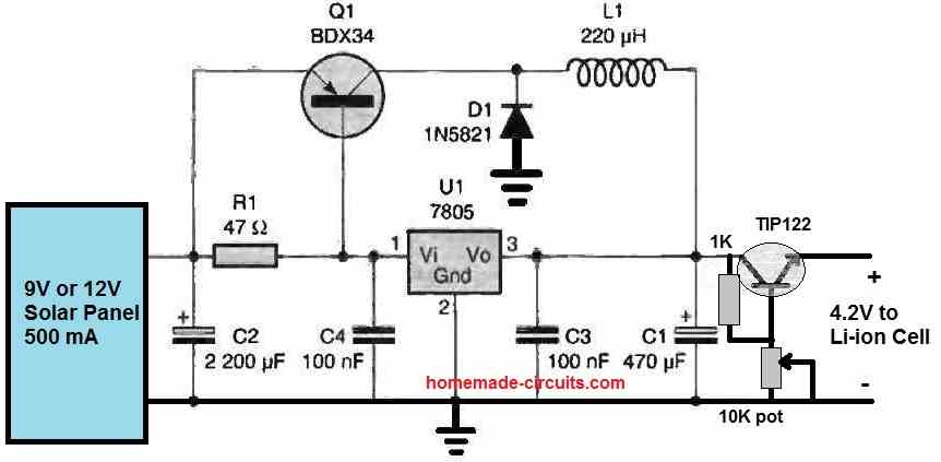
In this 7805 buck converter circuit around 80 % efficiency is achieved by the introduction of the Q1, D1 and L1. The Q1 transistor, along with the help of the blocking diode D1 and the inductor L1 transforms the excess 5 or 7 V into extra current for the connected battery.
This ensures lower heat dissipation from the IC 7805 and the BDX34, while delivering higher amount of current to the battery for efficient and quick charging.
The TIP122 emitter follower is actually linear regulator which is used to fine-tune the 5 V switching output into a 4.2 V charging voltage for the attached 3.7 V Li-ion cell.
Detailed explanation can be found in this article.
Solar Charger using LM317 Switching Regulator
LM317 is yet another linear regulator which can be transformed into a highly efficient solar switching regulator charger.
Inexpensive adjustable switching regulators can be constructed utilizing an LM317 as the governing component. The most rudimentary configuration is illustrated in the following figure.
The circuit can be used to efficiently charge any battery between 1.5 V and 24 V from solar panels rated between 9 V and 35 V.
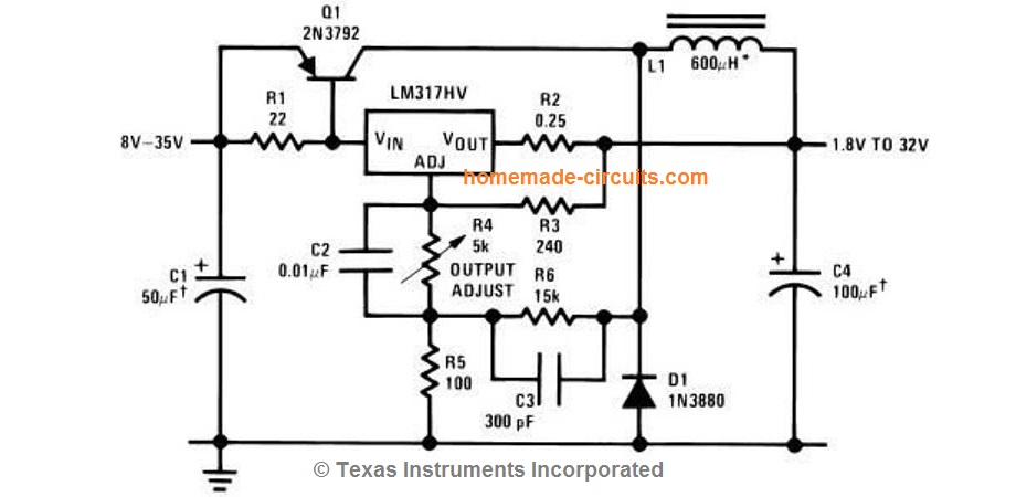
How it Works
A power PNP transistor functions as the actuator, propelling an L-C filter. Hysteresis is introduced to the LM317 via positive feedback facilitated by R6. Upon switching of the PNP transistor, a modest square wave is generated across R5.
Through the application of level shifting by means of R4 and C2, this square wave is then transferred to the regulator's adjustment terminal, thereby provoking its activation or deactivation.
The circuit is rendered oscillatory through the incorporation of negative feedback extracted from the output via R3.
Capacitor C3 serves to expedite the switching speed, while R2 restricts the maximum driving current supplied to Q1.
The efficiency of these regulators varies between 65% and 85%, contingent upon the desired output voltage.
Nevertheless, at lower output voltages, fixed power losses constitute a larger proportion of the overall output power, consequently yielding diminished efficiency.
The operational frequency hovers around 30 kHz, and the ripple factor is approximately 150 mV, contingent upon the input voltage.
Load regulation stands at roughly 50 mV, and line regulation is about 1% in response to a 10V alteration in input voltage.
For more detailed explanation about the above circuit, please refer to this link
Solar Charger using TL494 Switching Regulator Buck Converter
The PWM IC TL494 can be used to create a PWM switching buck converter regulator for charging batteries efficiently from solar panels.
An example circuit circuit diagram can be seen below:
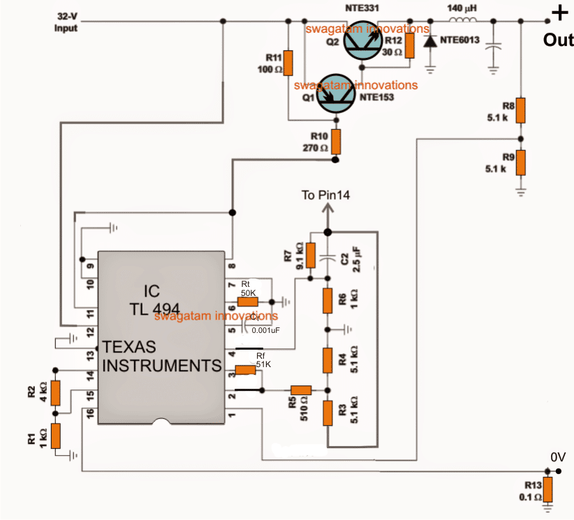
How it Works
The IC TL494 is configured as a high frequency PWM generator which is fed to power transistor based buck converter circuit.
The buck converter efficiently transforms the high voltage, low current from the solar panel into a low voltage, high current output, for charging a desired battery.
The output voltage can be adjusted by appropriately setting up the R8, R9 resistors.
Over current protection is provided by R13 resistor, which can be setup using the following formula:
R13 = 0.2 / Max charging current
More information about this design can be studied in this article.
Solar Charger using LM2576 Switching Power Supply Circuit
This is one of my favorites and is highly recommended if you are interested in constructing a highly efficient, adjustable 0 to 50 V solar battery carer circuit.
This LM2576-ADJ based solar charger circuit will allow to to build a wide variety of solar chargers ranging from 3 V to 50 V with around 85 % efficiency.
The complete circuit diagram is shown in the following figure.
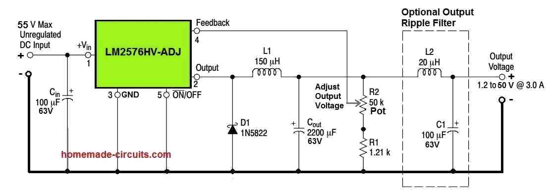
The diagram above illustrates a basic switching power supply circuit utilizing the LM2576HV-ADJ IC, which can generate a maximum output current of 3 amps while converting a 1.2 V input to a 50 V output.
How it Works
The following points provide information about the different aspects of the circuit:
- The IC's VIN pin, designated as pin#1, and the ground pin, labeled as pin#3, receive an unregulated 55 V DC input.
- To ensure effective reduction of ripple across the IC's input DC pins, the capacitor Cin is positioned in close proximity to the aforementioned pinouts.
- When the IC LM2576HV-ADJ is powered according to the previously mentioned process, its internal PWM oscillator activates.
- The PWM oscillator generates a predetermined amount of PWM internally, with the duty cycle of the PWM contingent on the feedback voltage applied to pin#4. This voltage is derived from the resistive divider pot R2 and R1.
- The calculated PWM is directed to the external buck converter stage, comprising components L1, D1, and Cout, via the IC's output pin#2.
- L1, D1, and Cout respond appropriately to the PWM in order to produce an optimized DC output voltage that is lowered to the desired level, ranging from 1.2 V to 50 V.
- It is important to note that the current reaches a maximum of 3 amps at the 35 V or 50 V outputs. Consequently, for lower output voltages, the current will be proportionally higher.
Complete explanation can be read in this article.
Solar Charger using Switching Boost Converter Circuit
So far I will explained switching solar regulators suitable for converting high voltage low current from a solar panel into a low voltage high current output for a battery.
However, if you wish to construct a solar charger with an opposite function, you can effectively using the following MOSFET boost converter circuit.
It will be able to convert any low voltage, high current solar output into a high voltage, low current output for charging relatively high voltage batteries.
You can customize it to charge batteries having voltages as high as 48 V.
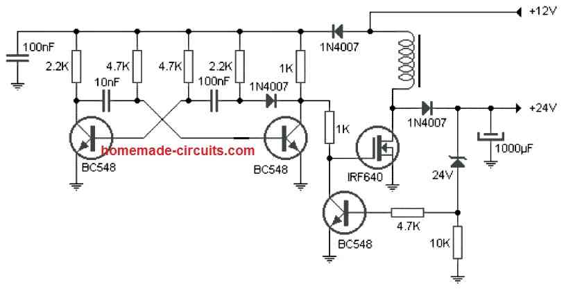
The complete circuit diagram can be seen in the following diagram:
How it Works
The demonstrated boost converter circuit exhibits a straightforward topology as it operates using a pair of conventional circuit stages comprising a transistorized astable stage and a boost converter stage.
The astable stage is constructed using two BC548 transistors, accompanied by the corresponding resistors and capacitors.
The frequency of the astable is determined by the interplay of the two capacitors and two base resistors.
This frequency is supplied to the gate of a MOSFET, which is configured as a boost converter in conjunction with its drain inductor.
The astable frequency propels the MOSFET and inductor at the designated frequency, resulting in a significantly amplified voltage across the drain and source of the MOSFET.
This increased voltage is accumulated across the 1000uF filter capacitor after appropriate rectification through the utilization of the 1N4007 diode.
The coil's number of turns may be equivalent to the level of the supply voltage; in this case, it is approximately 12 turns, with a diameter of approximately 20mm. The core material should be made of ferrite.
The feedback BC548 transistor ensures that the boosted voltage does not exceed 24V, which is determined by the 24V zener diode.
Consequently, it can be inferred that the proposed uncomplicated boost converter circuit's output can be customized according to the user's preference by simply increasing the number of turns and/or modifying the value of the 24V zener diode.
Conclusion
In conclusion, the utilization of switching regulators as solar chargers manifests a superior efficiency paradigm compared to their linear regulator counterparts.
This divergence in efficiency arises from the distinctive operational mechanisms employed by these two regulator types.
Switching regulators adeptly leverage high-frequency switching of power transistors to regulate voltage, enabling them to efficiently convert solar panel output to desired charging voltages through a dynamic energy transfer process.
This dynamic operation empowers switching regulators to swiftly modulate the energy flow, minimizing power dissipation and substantially reducing energy losses.
Conversely, linear regulators operate by dissipating excess energy as heat, thereby exhibiting inherent inefficiency when employed as solar chargers due to their static voltage regulation scheme.
Consequently, the judicious implementation of switching regulators in solar charging applications engenders a notable enhancement in overall efficiency, positioning them as the preferred choice for harnessing solar energy with optimal effectiveness and mitigated energy wastage.
no brightness of home made for charge controlar with 547